EP0159093B1 - Twine wrapping apparatus for a roll baling machine - Google Patents
Twine wrapping apparatus for a roll baling machine Download PDFInfo
- Publication number
- EP0159093B1 EP0159093B1 EP19850200564 EP85200564A EP0159093B1 EP 0159093 B1 EP0159093 B1 EP 0159093B1 EP 19850200564 EP19850200564 EP 19850200564 EP 85200564 A EP85200564 A EP 85200564A EP 0159093 B1 EP0159093 B1 EP 0159093B1
- Authority
- EP
- European Patent Office
- Prior art keywords
- twine
- baling machine
- dispensing
- machine according
- roll baling
- Prior art date
- Legal status (The legal status is an assumption and is not a legal conclusion. Google has not performed a legal analysis and makes no representation as to the accuracy of the status listed.)
- Expired
Links
Images




Classifications
-
- A—HUMAN NECESSITIES
- A01—AGRICULTURE; FORESTRY; ANIMAL HUSBANDRY; HUNTING; TRAPPING; FISHING
- A01F—PROCESSING OF HARVESTED PRODUCE; HAY OR STRAW PRESSES; DEVICES FOR STORING AGRICULTURAL OR HORTICULTURAL PRODUCE
- A01F15/00—Baling presses for straw, hay or the like
- A01F15/08—Details
- A01F15/14—Tying devices specially adapted for baling presses
- A01F15/141—Tying devices specially adapted for baling presses for round balers
Definitions
- This invention relates generally to roll baling machines typically referred to as round balers which form cylindrical roll bales of crop material.
- this invention relates to a twine wrapping apparatus including a twine cutting and clamping apparatus for such roll baling machines.
- U.S. Patent No. 4,167,844 discloses a twine wrapping apparatus including a drag link connected between a cam follower link and a driven link.
- the cam follower link carries a roller engaged with a cam plate, and the driven link is connected to a twine dispensing tube.
- the roller on the cam follower link follows the peripheral contour of the cam plate so that the cam follower link moves the drag link in a manner which results in rotation of the driven link and pivoting movement of the twine dispensing tube.
- a significant disadvantage of this twine wrapping apparatus is that precise adjustments of the cam plate and the drag link are required in order for the apparatus to operate properly.
- U.S. Patent No. 4,306,494 discloses a twine cutting and clamping apparatus which includes a twine guide fork movable into and out of a slot formed in a bracket.
- a twine cutting blade is fixed to the bottom of the bracket.
- the twine guide fork When the twine guide fork is moved into the slot in the bracket, the twine is pulled against the cutting blade to be cut.
- the twine is also clamped between a bar formed on the twine guide fork and the sides of the slot in the bracket.
- the twine guide fork is moved out of the bracket slot, the twine is released.
- a disadvantage of this apparatus is that the twine must be pulled very taut in order to be effectively cut by the cutting blade.
- U.S. Patent No. 4,169,410 discloses a twine severing mechanism including a pair of cutting blades movable into and out of engagement with a pair of striker plates to cut twine.
- the cutting blades are mounted on an elongated rod, and their movement is controlled by a pair of control rods which are connected to a pair of latch plates. When the control rods are displaced, substantially simultaneous movement of the cutting blades is effected due to the elongated rod and the latch plates.
- a disadvantage of this twine severing mechanism is that it is rather complex and thus difficult to assemble.
- U.S. 3,064,556 discloses a very complicated twine wrapping apparatus for a roll baling machine and which includes two twine dispensing members which are mounted on the base frame for pivotal movement back-and-forth between retracted rest positions and wrapping start positions.
- Complicated actuator means are provided which include a shuttle member which is movable back-and-forth between opposed extreme positions along a generally rectilinear path. Said shuttle member is drivingly connected to the twine dispensing members for, upon movement of the former along said generally rectilinear path, causing the latter to pivot.
- a gear rack is carried on the shuttle member which is cooperable with a gear segment; said gear rack and gear segment forming part of the actuator means and being operable to move the shuttle member along said generally rectilinear path.
- the present invention is directed to a novel twine wrapping apparatus for use in a roll baling machine having a base frame; the twine wrapping apparatus comprising:
- the twine wrapping apparatus comprises:
- the twine wrapping apparatus also comprises a twine cutting and clamping means including a cutting member, a resilient member, and an arm movable between a closed position and an open position.
- the arm has a first edge which cooperates with the cutting member to cut twine between this first edge of the arm and the cutting member when the arm is moved to the closed position.
- the arm also has a second edge which cooperates with the resilient member to clamp twine between this second edge of the arm and the resilient member when the arm is moved to the closed position. The twine is released from being clamped between the second edge of the arm and the resilient member when the arm is moved to the open position.
- the twine cutting and clamping means include .
- First and second spur gears are connected, respectively, to the first and second arms, and the first and second spur gears are in intermeshing engagement with each other.
- the mechanism also includes a lever connected to the first arm for pivoting the first arm. The first and second spur gears cause concurrent pivoting of the second arm when the first arm is pivoted by the lever.
- a breakaway mechanism may be provided coupling the twine dispensing member to the gear segment for permitting the twine dispensing member to be uncoupled from the gear segment when a predetermined load is exerted on the twine dispensing member during its pivoting movement.
- the breakaway mechanism may include a plate secured to the twine dispensing member with projections formed thereon for engagement in grooves formed in a plate coupled to . the gear segment.
- a spring is also provided in the breakaway mechanism to urge the projections on the plate into the grooves in the gear segment.
- a roll baling machine incorporating the preferred embodiment of the present invention includes a base frame 10 supported by a pair of wheels 12, and a rear frame 14 pivotally connected at 16 to the base frame 10 by suitable bearings.
- a pickup unit 18 is mounted on the base frame 10 and is supported by wheels 20.
- a floor roller 22, guide members 24, and drive sprockets 26 are rotatably mounted on the base frame 10.
- cam guide members 28 are supported on the base frame 10:
- An arm assembly 30 is rotatably mounted on the base frame 10 by a tube 32, and the arm assembly 30 carries guide members 34 which are rotatable.
- a plurality of guide members 36 are rotatably supported on the rear frame 14.
- a bale forming apron 38 is movably supported on the drive sprockets 26, the guide members 24, 34 and 36, and the cam guide members 28.
- the bale forming apron 38 is preferably comprised of a pair of endless link type chains connected at spaced intervals by transverse bars or slats.
- the apron 38 is supported on the cam guide members 28 to define a bale chamber having an initial wedge shape in side elevation.
- the apron 38 is lifted off the cam guide members 28 as the bale chamber expands to a generally cylindrical shape.
- a twine wrapping apparatus 42 is supported on the base frame 10 and a twine box 44 is provided for supplying twine to the twine wrapping apparatus 42.
- the twine wrapping apparatus 42 includes a support beam 46 which extends transversely between the side walls lIa,lIb of the base frame 10 and is connected thereto by bolts 48.
- the beam 46 is of a generally inverted U-shaped cross section.
- the twine wrapping apparatus 42 also includes a shuttle member 50 which is supported at its ends by rods 52a, 52b slidably disposed in bearings 54 mounted in the side walls 11a, 11b for permitting movement of the shuttle member 50 generally transversely of the base frame 10 in the space 11 defined between the side walls 11a, 11b.
- the shuttle member 50 is generally channel or top hat-shaped in cross section.
- Twine dispensing members such as twine tubes or arms 56 are rotatably supported on the support beam 46, and strands of twine 58 extend from the twine box 44 through twine guides 60 mounted on the support beam 46, then through the twine tubes 56 and into a cut and clamp mechanism 62 which is also supported on the support beam 46.
- the twine tubes 56 are each welded to the lower one of a pair of plates 64 as seen in Fig. 5, and the plates 64 are connected to each other by bolts 66.
- the plates 64 are fixed to pinions 68 by bolts 70, only one bolt 70 being shown in Fig. 5.
- the pinions 68 are rotatably mounted on shafts 72 which are fixed at their upper ends to the support beam 46.
- the pinions 68 may be replaced by gear segments of preferably more than 90° but less than 180°.
- a pair of washers 74 and a bearing member 76 are disposed between the upper side of each pinion 68 and a stabilizer block 78 which is positioned between the uppermost washer 74 and the support beam 46.
- the shuttle member 50 carries gear racks 86 which have teeth in intermeshing engagement with the teeth of the pinions 68. As seen in Fig. 4, openings 88 are provided in the top of the shuttle member 50 near the ends thereof to accommodate the stabilizer blocks 78, and another opening 90 is provided in the top of the shuttle member 50 near the center thereof to accommodate the cut and clamp mechanism 62.
- the mechanism 92 for actuating the twine wrapping apparatus 42 includes a linear actuator 94 which is pivotably connected at one end to a bracket 96 and at the other end to a lever arm 98.
- the bracket 96 is secured to side wall 11a of the base frame 10 by bolts 100.
- the lever arm 98 is pivotably connected by a pin 102 to a bracket 104 which is fixed to the side wall 11a a of the base frame 10 by two of the bolts 48 and by a further bolt 106.
- the lever arm 98 is also pivotably connected by a pin 108 to the end of the rod 52a which extends through the side wall 11a of the base frame 10.
- the lever arm 98 is pivoted on pin 102 from the position shown in full lines to the phantom position thereby moving the shuttle member 50 generally transversely toward the side wall Ila of the base frame 10.
- This causes the gear racks 86 on the shuttle member 50 to move in a direction which will cause concurrent rotation of the pinions 68 on the shafts 72 in opposite directions with respect to each other.
- Such rotation of the pinions 68 will cause simultaneous pivoting movement of the twine tubes 56 in opposite directions with respect to each other from their home or rest positions shown in full lines to their dispensing positions shown in phantom lines at 56".
- the twine dispensing tube 56 Opposite pivoting movement of the twine dispensing tube 56 is obtained by providing the respective gear racks 86 at opposite sides of the respective pivotal mountings of said twine dispensing tubes 56. Subsequent contraction of the linear actuator 94 will move the shuttle member 50 back toward the side wall 11 b of the base frame 10 and thereby cause simultaneous pivoting movement of the twine tubes 56 back to their home or rest positions shown in full lines. As can be taken from Fig. 2, the twine dispensing tubes 56 preferably have.their pivotal mountings proximate to the respective opposite side walls 11 a and 11 b and generally face each other when positioned in their rest positions.
- the twine dispensing tubes 56 When moved to their twine dispensing positions, said twine dispensing tubes 56 extend generally parallel to the adjacent side walls 11a, 11b. Consequently the twine dispensing tubes 56 are pivoted through an arc of generally a quarter of a circle when moved between their rest and twine dispensing positions. Actually the arc of movement is slightly more than 90° but is subtantially less than 180°, as can be derived from Fig. 2. Accordingly, the pinions 68, during operation, are used only for about slightly more than a quarter of their circumference. Hence said pinions 68 may be replaced by gear segments of slightly more than 90° in circumference. As seen in Figs. 6,7, and 8, the cut and clamp mechanism 62 includes a body member 110 which is fastened to the support beam 46 by four bolts 112. A pair of arms 114 are mounted on pins 116 which are pivoted on the body, member 110.
- Intermeshing spur gears 118 are fixed to the arms 114.
- Pockets 120 are provided in the bottom of the body member 110 to accommodate portions of the arms 114 when they are pivoted to the closed positions shown in full lines in Fig. 7 and 8.
- a lever 122 is fixed to one of the pins 116, and carries rollers 124 and 126.
- Tension springs 128 are connected between bolts 130 which are fastened to the body member 110 and bolts 132 which are connected to the arms 114.
- cutting members such as knives 134 and generally U-shaped spring clips 136 having resilient legs 137 are fastened to the body member 110 and are disposed in the pockets 120.
- a pair of cam members 138 are secured to the shuttle member 50. Each of the cam members 138 has a first cam surface 140 and a second cam surface 142 arranged for engaging the rollers 124 and 126, respectively, on the lever 122.
- Figs. 9-13 The twine cutting and clamping operation of the cut and clamp mechanism 62 will be best understood by referring to Figs. 9-13.
- the strands of twine 58 are each initially clamped between an edge of one of the arms 114 and the resilient leg 137 of one of the spring clips 136 when the arms 114 are in their closed positions.
- the arms 114 move toward their partially open positions, as shown in Fig. 10
- the strands of twine 58 are released.
- the strands of twine 58 remain released as the arms 114 move to their fully open position shown in Fig. 11 and also as the arms 114 move back toward their closed position as shown in Fig. 12.
- the arms 114 are snapped back into their closed position by the springs 128 as shown in Fig.
- each strand of twine 58 is cut by a rapid shearing or scissors type action between an edge of one of the arms 114 and the. cutting edge of one of the knives 134 while being simultaneously clamped between the other edge of the arm 114 and the resilient leg 137 of the spring clip 136.
- the twine tubes 56 are disposed in their home or rest positions shown in full lines in Fig. 2 and the arms 114 are in their closed positions so that the strands of twine 58 are clamped in the cut and clamp mechanism 62.
- the linear actuator 94 is extended thereby moving the shuttle member 50 toward the sidewall Ila of the base frame 10. This movement of the shuttle member 50 causes the twine tubes 56 to be pivoted, due to the gear racks 86 and the pinions 68, toward the positions indicated in phantom lines at 56' in Fig.
- twine tubes 56 move from the phantom positions 56' to their dispensing positions 56"
- the arms 114 are moved from their closed positions to their fully open positions 114" and the strands of twine 58 are released from the cut and clamp mechanism 62.
- the twine tails are fed into the bale chamber in order to be caught between the floor roller 22 and the rotating bale.
- the linear actuator 94 is then contracted to move the shuttle member 50 back toward the sidewall 11 b of the base frame 10 and thereby pivot the twine tubes 56 from their dispensing positions 56" back toward their home positions shown in full lines in Fig. 2.
- twine is wrapped around the bale in a spiral manner.
- twine wrapping apparatus 42 is ready to wrap the next bale with twine.
- linear actuator 94 may be in the form of an electric servomotor or a hydraulic piston and cylinder unit. Furthermore, the linear actuator 94 may take the form of a manual device such .as a threaded rod.
- twine wrapping apparatus may employ only one twine tube or any other number of twine tubes.
- the shuttle member 50 slidably may be supported on the support beam 46 as opposed to being mounted on the side walls 11a, 11b by the bearings 54.
- the actuating means 92 alternatively may be provided inside the space defined between the opposite side walls 11 a, 11 b.
- shuttle member 50 While in the preferred embodiment the shuttle member 50 is mounted for rectilinear movement transversely of the width of the baling machine, it will be evident that the shuttle memer 50 may be movable in other directions and indeed even may be movable in a generally fore-and-aft direction of the machine. More generally the shuttle member 50 is movable back-and-forth along a generally rectilinear path between opposed extreme positions and is drivingly connected to the or each twine dispensing tube 56.
- the twine dispensing apparatus as described herebefore also advantageously may include a breakaway mechanism coupling the or each twine tube 50 to its respective driving pinion 68.
- the breakaway mechanism permits the twine dispensing tube 56 to be uncoupled from its driving pinion 68 when a predetermined load is exerted on the twine-dispensing tube 56 during its pivoting movement.
- the breakaway mechanism may include the lower plate 64 secured to the twine dispensing tube 56 and which is provided with projections formed thereon for engagement in grooves formed in the upper plate 64 coupled to the pinion 68.
- a spring is also provided in the breakaway mechanism to urge the projections on the lower plate 64 into the grooves in the upper plate 64.
- the bolts 66 coupling the upper and lower plates 64 to each other may be shearbolts arranged to be sheared off when the twine dispensing tube 56 is overloaded.
Landscapes
- Life Sciences & Earth Sciences (AREA)
- Environmental Sciences (AREA)
- Auxiliary Devices For And Details Of Packaging Control (AREA)
Description
- This invention relates generally to roll baling machines typically referred to as round balers which form cylindrical roll bales of crop material. In particular, this invention relates to a twine wrapping apparatus including a twine cutting and clamping apparatus for such roll baling machines.
- U.S. Patent No. 4,167,844 discloses a twine wrapping apparatus including a drag link connected between a cam follower link and a driven link. The cam follower link carries a roller engaged with a cam plate, and the driven link is connected to a twine dispensing tube. When the cam plate is rotated, the roller on the cam follower link follows the peripheral contour of the cam plate so that the cam follower link moves the drag link in a manner which results in rotation of the driven link and pivoting movement of the twine dispensing tube. A significant disadvantage of this twine wrapping apparatus is that precise adjustments of the cam plate and the drag link are required in order for the apparatus to operate properly.
- U.S. Patent No. 4,306,494 discloses a twine cutting and clamping apparatus which includes a twine guide fork movable into and out of a slot formed in a bracket. A twine cutting blade is fixed to the bottom of the bracket. When the twine guide fork is moved into the slot in the bracket, the twine is pulled against the cutting blade to be cut. The twine is also clamped between a bar formed on the twine guide fork and the sides of the slot in the bracket. When the twine guide fork is moved out of the bracket slot, the twine is released. A disadvantage of this apparatus is that the twine must be pulled very taut in order to be effectively cut by the cutting blade.
- U.S. Patent No. 4,169,410 discloses a twine severing mechanism including a pair of cutting blades movable into and out of engagement with a pair of striker plates to cut twine. The cutting blades are mounted on an elongated rod, and their movement is controlled by a pair of control rods which are connected to a pair of latch plates. When the control rods are displaced, substantially simultaneous movement of the cutting blades is effected due to the elongated rod and the latch plates. A disadvantage of this twine severing mechanism is that it is rather complex and thus difficult to assemble.
- Finally, U.S. 3,064,556 discloses a very complicated twine wrapping apparatus for a roll baling machine and which includes two twine dispensing members which are mounted on the base frame for pivotal movement back-and-forth between retracted rest positions and wrapping start positions. Complicated actuator means are provided which include a shuttle member which is movable back-and-forth between opposed extreme positions along a generally rectilinear path. Said shuttle member is drivingly connected to the twine dispensing members for, upon movement of the former along said generally rectilinear path, causing the latter to pivot. A gear rack is carried on the shuttle member which is cooperable with a gear segment; said gear rack and gear segment forming part of the actuator means and being operable to move the shuttle member along said generally rectilinear path.
- It is therefore an object of the present invention to provide a new twine wrapping apparatus including a twine dispensing member and twine clamping and twine cutting means and which is simple in design and therefore is easy to assemble without requiring critical adjustments and which furthermore is efficient and trouble free in operation.
- The present invention is directed to a novel twine wrapping apparatus for use in a roll baling machine having a base frame; the twine wrapping apparatus comprising:
- a twine dispensing member mounted on the base frame for pivotal movement back-and-forth between a retracted rest position and a dispensing start position;
- a shuttle member movably supported on the base frame for back-and-forth movement between opposed extreme positions along a generally rectilinear path; said shuttle member being drivingly connected to the twine dispensing member for, upon movement of the former along said generally rectilinear path, causing the latter to pivot from the rest position to the dispensing start position when the shuttle member is shifted in a first direction and from the dispensing start position to the rest position when the shuttle member is shifted in a further direction opposite to the first direction; and
- actuating means supported on the base frame and operable to move the shuttle member along said generally rectilinear path.
- Said twine wrapping apparatus further also comprises a gear segment which is cooperable with a gear rack carried on the shuttle member.
- Said roll baling machine is characterized in that:
- the actuating means are operatively connected to the shuttle member in a manner to move by force the latter back-and-forth along said generally rectilinear path; and
- the gear segment is fixedly coupled to the twine dispensing member and is in permanent intermeshing engagement with the gear rack on the shuttle member to translate said back-and-forth, generally rectilinear movement of the shuttle member into said back-and-forth rotational movement of the dispensing member.
- In a preferred embodiment of the invention, the twine wrapping apparatus comprises:
- first and second twine dispensing members pivotally mounted on the base frame,
- first and second gear segments connected to the first and second twine dispensing members, respectively; and
- first and second gear racks carried on said shuttle member in permanent intermeshing engagement with the first and second gear segments, respectively, for, upon back-and-forth movement of the shuttle member along said generally rectilinear path, pivoting the first and second twine dispensing members.
- The twine wrapping apparatus according to the present invention also comprises a twine cutting and clamping means including a cutting member, a resilient member, and an arm movable between a closed position and an open position. The arm has a first edge which cooperates with the cutting member to cut twine between this first edge of the arm and the cutting member when the arm is moved to the closed position. The arm also has a second edge which cooperates with the resilient member to clamp twine between this second edge of the arm and the resilient member when the arm is moved to the closed position. The twine is released from being clamped between the second edge of the arm and the resilient member when the arm is moved to the open position.
- In the preferred embodiment of the invention comprising the dual twine wrapping apparatus, the twine cutting and clamping means include . first and second cutting members, first and second resilient members and first and second arms each having one edge adapted for, in cooperation with a corresponding cutting member, cutting twine and another edge adapted for, in cooperation with a corresponding resilient member, clamping twine. First and second spur gears are connected, respectively, to the first and second arms, and the first and second spur gears are in intermeshing engagement with each other. The mechanism also includes a lever connected to the first arm for pivoting the first arm. The first and second spur gears cause concurrent pivoting of the second arm when the first arm is pivoted by the lever.
- A breakaway mechanism may be provided coupling the twine dispensing member to the gear segment for permitting the twine dispensing member to be uncoupled from the gear segment when a predetermined load is exerted on the twine dispensing member during its pivoting movement.
- The breakaway mechanism may include a plate secured to the twine dispensing member with projections formed thereon for engagement in grooves formed in a plate coupled to . the gear segment. A spring is also provided in the breakaway mechanism to urge the projections on the plate into the grooves in the gear segment.
- A roll baling machine embodying the present invention will now be described in greater detail by way of example with reference to the accompanying drawings, in which:
- Fig. 1 is a side elevation view of a roll baling machine incorporating the preferred embodiment of the twine wrapping apparatus;
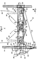
- Fig. 2 is an enlarged sectional view taken on lines 2-2 of Fig. 1;
- Fig. 3 is a view taken on lines 3-3 of Fig. 2;
- Fig. 4 is a view taken on lines 4-4 of Fig. 3;
- Fig. 5 is an enlarged sectional view taken on lines 5-5 of Fig. 3;
- Fig. 6 is an enlarged sectional view taken on lines 6-6 of Fig. 3;
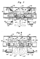
- Fig. 7 is an enlarged sectional view taken on lines 7-7 of Fig. 2;
- Fig. 8 is an enlarged sectional view taken on lines 8-8 of Fig 2;
- Fig. 9 is an enlarged sectional view taken on lines 9-9 of Fig. 3; and
- Figs. 10-13 are schematic views of the mechanism shown in Figs. 6-9.
- Referring to Fig. 1, a roll baling machine incorporating the preferred embodiment of the present invention includes a
base frame 10 supported by a pair ofwheels 12, and arear frame 14 pivotally connected at 16 to thebase frame 10 by suitable bearings. Apickup unit 18 is mounted on thebase frame 10 and is supported bywheels 20. Afloor roller 22,guide members 24, and drivesprockets 26 are rotatably mounted on thebase frame 10. Also,cam guide members 28 are supported on the base frame 10: Anarm assembly 30 is rotatably mounted on thebase frame 10 by atube 32, and thearm assembly 30 carriesguide members 34 which are rotatable. A plurality ofguide members 36 are rotatably supported on therear frame 14. Abale forming apron 38 is movably supported on thedrive sprockets 26, theguide members cam guide members 28. Thebale forming apron 38 is preferably comprised of a pair of endless link type chains connected at spaced intervals by transverse bars or slats. When the machine is empty, theapron 38 is supported on thecam guide members 28 to define a bale chamber having an initial wedge shape in side elevation. During bale formation, theapron 38 is lifted off thecam guide members 28 as the bale chamber expands to a generally cylindrical shape. - According to the present invention, a
twine wrapping apparatus 42 is supported on thebase frame 10 and atwine box 44 is provided for supplying twine to thetwine wrapping apparatus 42. As seen in Figs. 2, 3, and 4, thetwine wrapping apparatus 42 includes asupport beam 46 which extends transversely between the side walls lIa,lIb of thebase frame 10 and is connected thereto bybolts 48. As seen in Fig. 5, thebeam 46 is of a generally inverted U-shaped cross section. Thetwine wrapping apparatus 42 also includes ashuttle member 50 which is supported at its ends byrods bearings 54 mounted in the side walls 11a, 11b for permitting movement of theshuttle member 50 generally transversely of thebase frame 10 in the space 11 defined between the side walls 11a, 11b. As seen in Fig. 5, theshuttle member 50 is generally channel or top hat-shaped in cross section. Twine dispensing members such as twine tubes orarms 56 are rotatably supported on thesupport beam 46, and strands oftwine 58 extend from thetwine box 44 through twine guides 60 mounted on thesupport beam 46, then through thetwine tubes 56 and into a cut andclamp mechanism 62 which is also supported on thesupport beam 46. - The
twine tubes 56 are each welded to the lower one of a pair ofplates 64 as seen in Fig. 5, and theplates 64 are connected to each other bybolts 66. Theplates 64 are fixed topinions 68 bybolts 70, only onebolt 70 being shown in Fig. 5. Thepinions 68 are rotatably mounted onshafts 72 which are fixed at their upper ends to thesupport beam 46. As will be apparent from what follows hereafter, thepinions 68 may be replaced by gear segments of preferably more than 90° but less than 180°. A pair ofwashers 74 and a bearingmember 76 are disposed between the upper side of eachpinion 68 and astabilizer block 78 which is positioned between theuppermost washer 74 and thesupport beam 46. Another pair ofwashers 75 and another bearingmember 77 are disposed underneath thelowermost plate 64, and abolt 80 is threaded into the bottom end of eachshaft 72. Aspacer collar 82 and awasher 84 are disposed between thelowermost washer 75 and the head of eachbolt 80. When thebolts 80 are tightened into theshafts 72, thetwine tubes 56 are, in effect, fixed to and will rotate with thepinions 68 as will be described later. Theshuttle member 50 carries gear racks 86 which have teeth in intermeshing engagement with the teeth of thepinions 68. As seen in Fig. 4,openings 88 are provided in the top of theshuttle member 50 near the ends thereof to accommodate the stabilizer blocks 78, and anotheropening 90 is provided in the top of theshuttle member 50 near the center thereof to accommodate the cut andclamp mechanism 62. - Referring now to Fig. 2, the
mechanism 92 for actuating thetwine wrapping apparatus 42 includes alinear actuator 94 which is pivotably connected at one end to abracket 96 and at the other end to alever arm 98. Thebracket 96 is secured to side wall 11a of thebase frame 10 bybolts 100. Thelever arm 98 is pivotably connected by apin 102 to abracket 104 which is fixed to the side wall 11a a of thebase frame 10 by two of thebolts 48 and by afurther bolt 106. Thelever arm 98 is also pivotably connected by apin 108 to the end of therod 52a which extends through the side wall 11a of thebase frame 10. When thelinear actuator 94 is extended as shown in Fig. 2, thelever arm 98 is pivoted onpin 102 from the position shown in full lines to the phantom position thereby moving theshuttle member 50 generally transversely toward the side wall Ila of thebase frame 10. This causes the gear racks 86 on theshuttle member 50 to move in a direction which will cause concurrent rotation of thepinions 68 on theshafts 72 in opposite directions with respect to each other. Such rotation of thepinions 68 will cause simultaneous pivoting movement of thetwine tubes 56 in opposite directions with respect to each other from their home or rest positions shown in full lines to their dispensing positions shown in phantom lines at 56". Opposite pivoting movement of thetwine dispensing tube 56 is obtained by providing the respective gear racks 86 at opposite sides of the respective pivotal mountings of saidtwine dispensing tubes 56. Subsequent contraction of thelinear actuator 94 will move theshuttle member 50 back toward the side wall 11 b of thebase frame 10 and thereby cause simultaneous pivoting movement of thetwine tubes 56 back to their home or rest positions shown in full lines. As can be taken from Fig. 2, thetwine dispensing tubes 56 preferably have.their pivotal mountings proximate to the respective opposite side walls 11 a and 11 b and generally face each other when positioned in their rest positions. When moved to their twine dispensing positions, saidtwine dispensing tubes 56 extend generally parallel to the adjacent side walls 11a, 11b. Consequently thetwine dispensing tubes 56 are pivoted through an arc of generally a quarter of a circle when moved between their rest and twine dispensing positions. Actually the arc of movement is slightly more than 90° but is subtantially less than 180°, as can be derived from Fig. 2. Accordingly, thepinions 68, during operation, are used only for about slightly more than a quarter of their circumference. Hence said pinions 68 may be replaced by gear segments of slightly more than 90° in circumference. As seen in Figs. 6,7, and 8, the cut andclamp mechanism 62 includes abody member 110 which is fastened to thesupport beam 46 by fourbolts 112. A pair ofarms 114 are mounted onpins 116 which are pivoted on the body,member 110. - Intermeshing spur gears 118 are fixed to the
arms 114.Pockets 120 are provided in the bottom of thebody member 110 to accommodate portions of thearms 114 when they are pivoted to the closed positions shown in full lines in Fig. 7 and 8. Alever 122 is fixed to one of thepins 116, and carriesrollers bolts 130 which are fastened to thebody member 110 andbolts 132 which are connected to thearms 114. As best seen in Fig. 6, cutting members such asknives 134 and generally U-shaped spring clips 136 havingresilient legs 137 are fastened to thebody member 110 and are disposed in thepockets 120. A pair ofcam members 138 are secured to theshuttle member 50. Each of thecam members 138 has afirst cam surface 140 and a second cam surface 142 arranged for engaging therollers lever 122. - When the
shuttle member 50 is moved toward the right in Fig. 8, thecam surface 140 on the left-hand cam member 138 engages theroller 124 on thelever 122 and pivots thelever 122 to the position shown in phantom at 122'. Further movement of theshuttle member 50 toward the right in Fig. 8 causes the cam surface 142 on the left-hand cam member 138 to engage theroller 126 on thelever 122 thereby pivoting thelever 122 to the position indicated in phantom at 122". This pivoting movement of thelever 122 causes the intermeshing spur gears 118 to be rotated, resulting in concurrent pivoting movement of thearms 114 to their partially open positions shown in phantom at 114' and finally to their fully open positions indicated in phantom at 114". As thearms 114 are pivoted to their fullyopen positions 114", thesprings 128 seen in Fig. 7 will move slightly over center with respect to thepins 116 and will hold thearms 114 in that position. Subsequent opposite movement of theshuttle member 50 toward the left in Fig. 8 will result in the right-hand cam member 138 pivoting thearms 114 back toward their closed positions shown in full lines. As thearms 114 reach their partially open positions 114', thesprings 128 will move sufficiently back over center with respect to thepins 116 to quickly snap thearms 114 back into their closed positions. - The twine cutting and clamping operation of the cut and
clamp mechanism 62 will be best understood by referring to Figs. 9-13. As seen in Fig. 9, the strands oftwine 58 are each initially clamped between an edge of one of thearms 114 and theresilient leg 137 of one of the spring clips 136 when thearms 114 are in their closed positions. As thearms 114 move toward their partially open positions, as shown in Fig. 10, the strands oftwine 58 are released. The strands oftwine 58 remain released as thearms 114 move to their fully open position shown in Fig. 11 and also as thearms 114 move back toward their closed position as shown in Fig. 12. As thearms 114 are snapped back into their closed position by thesprings 128 as shown in Fig. 13, each strand oftwine 58 is cut by a rapid shearing or scissors type action between an edge of one of thearms 114 and the. cutting edge of one of theknives 134 while being simultaneously clamped between the other edge of thearm 114 and theresilient leg 137 of thespring clip 136. - During the formation of a roll bale in the machine of Fig. 1, the
twine tubes 56 are disposed in their home or rest positions shown in full lines in Fig. 2 and thearms 114 are in their closed positions so that the strands oftwine 58 are clamped in the cut andclamp mechanism 62. When the roll bale has been completed and it is desired to wrap the bale with twine, thelinear actuator 94 is extended thereby moving theshuttle member 50 toward the sidewall Ila of thebase frame 10. This movement of theshuttle member 50 causes thetwine tubes 56 to be pivoted, due to the gear racks 86 and thepinions 68, toward the positions indicated in phantom lines at 56' in Fig. 2 while the strands oftwine 58 remain clamped in the cut andclamp mechanism 62. By clamping the strands oftwine 58 in the cut andclamp mechanism 62 while thetwine tubes 56 are moved from their home positions to their phantom positions 56', relatively long twine tails are generated on the strands oftwine 58. Further movement of theshuttle member 50 toward the sidewall 11 a of thebase frame 10 causes thetwine tubes 56 to be pivoted to their dispensing positions shown in phantom at 56" in Fig. 2. As thetwine tubes 56 move from the phantom positions 56' to theirdispensing positions 56", thearms 114 are moved from their closed positions to their fullyopen positions 114" and the strands oftwine 58 are released from the cut andclamp mechanism 62. The twine tails are fed into the bale chamber in order to be caught between thefloor roller 22 and the rotating bale. Thelinear actuator 94 is then contracted to move theshuttle member 50 back toward the sidewall 11 b of thebase frame 10 and thereby pivot thetwine tubes 56 from theirdispensing positions 56" back toward their home positions shown in full lines in Fig. 2. During this pivoting movement of thetwine tubes 56, twine is wrapped around the bale in a spiral manner. As thetwine tubes 56 reach their home positions, thearms 114 are snapped back to their closed positions by thesprings 128 and the strands oftwine 58 are simultaneously cut and clamped in the cut andclamp mechanism 62. The wrapped bale is then discharged from the machine by pivoting therear frame 14 upwardly in a known manner. Thetwine wrapping apparatus 42 is ready to wrap the next bale with twine. - It will be understood that the
linear actuator 94 may be in the form of an electric servomotor or a hydraulic piston and cylinder unit. Furthermore, thelinear actuator 94 may take the form of a manual device such .as a threaded rod. - It will also be understood that the present invention is not limited to the arrangement as disclosed in the preferred embodiment of the twine wrapping apparatus where two
twine tubes 56 are employed. Alternatively, the twine wrapping apparatus of the present invention may employ only one twine tube or any other number of twine tubes. - It will also be understood that the
shuttle member 50 slidably may be supported on thesupport beam 46 as opposed to being mounted on the side walls 11a, 11b by thebearings 54. Similarly, the actuating means 92 alternatively may be provided inside the space defined between the opposite side walls 11 a, 11 b. - While in the preferred embodiment the
shuttle member 50 is mounted for rectilinear movement transversely of the width of the baling machine, it will be evident that theshuttle memer 50 may be movable in other directions and indeed even may be movable in a generally fore-and-aft direction of the machine. More generally theshuttle member 50 is movable back-and-forth along a generally rectilinear path between opposed extreme positions and is drivingly connected to the or eachtwine dispensing tube 56. - The twine dispensing apparatus as described herebefore also advantageously may include a breakaway mechanism coupling the or each
twine tube 50 to itsrespective driving pinion 68. The breakaway mechanism permits thetwine dispensing tube 56 to be uncoupled from its drivingpinion 68 when a predetermined load is exerted on the twine-dispensingtube 56 during its pivoting movement. The breakaway mechanism may include thelower plate 64 secured to thetwine dispensing tube 56 and which is provided with projections formed thereon for engagement in grooves formed in theupper plate 64 coupled to thepinion 68. A spring is also provided in the breakaway mechanism to urge the projections on thelower plate 64 into the grooves in theupper plate 64. Alternatively thebolts 66 coupling the upper andlower plates 64 to each other may be shearbolts arranged to be sheared off when thetwine dispensing tube 56 is overloaded. - The following claims are intended to cover all modifications and variations of the preferred embodiments of the invention without departing from the spirit and scope of the invention.
Claims (18)
Applications Claiming Priority (6)
| Application Number | Priority Date | Filing Date | Title |
|---|---|---|---|
| US600872 | 1984-04-16 | ||
| US600745 | 1984-04-16 | ||
| US06/600,750 US4517889A (en) | 1984-04-16 | 1984-04-16 | Twine cutting and clamping apparatus for a roll baling machine |
| US06/600,872 US4517890A (en) | 1984-04-16 | 1984-04-16 | Twine wrapping apparatus for a roll baling machine |
| US06/600,745 US4505197A (en) | 1984-04-16 | 1984-04-16 | Twine cut and clamp mechanism for a roll baling machine |
| US600750 | 1984-04-16 |
Publications (3)
| Publication Number | Publication Date |
|---|---|
| EP0159093A2 EP0159093A2 (en) | 1985-10-23 |
| EP0159093A3 EP0159093A3 (en) | 1986-11-26 |
| EP0159093B1 true EP0159093B1 (en) | 1989-11-02 |
Family
ID=27416816
Family Applications (1)
| Application Number | Title | Priority Date | Filing Date |
|---|---|---|---|
| EP19850200564 Expired EP0159093B1 (en) | 1984-04-16 | 1985-04-15 | Twine wrapping apparatus for a roll baling machine |
Country Status (2)
| Country | Link |
|---|---|
| EP (1) | EP0159093B1 (en) |
| DE (1) | DE3573976D1 (en) |
Families Citing this family (2)
| Publication number | Priority date | Publication date | Assignee | Title |
|---|---|---|---|---|
| FR2604857B1 (en) * | 1986-10-10 | 1989-01-06 | Rivierre Casalis | METHOD AND DEVICE FOR CONTROLLING GUIDING ARM OF TWIN BINDING CYLINDRICAL BALES IN A HARVESTER PRESS |
| CN116076248B (en) * | 2023-02-27 | 2024-08-16 | 河南农业大学 | Round bale rope winding mechanism |
Family Cites Families (6)
| Publication number | Priority date | Publication date | Assignee | Title |
|---|---|---|---|---|
| US3064556A (en) * | 1957-11-06 | 1962-11-20 | Inc Promoting Enduring Peace | Rotary baler improvement |
| US4072095A (en) * | 1976-08-30 | 1978-02-07 | Sperry Rand Corporation | Twine wrapping mechanism for a roll forming machine |
| DE2645762C3 (en) * | 1976-10-09 | 1982-07-22 | Gebrüder Welger GmbH & Co KG, 3340 Wolfenbüttel | Device for tying a roll bale of agricultural stalks |
| FR2483166A1 (en) * | 1980-05-29 | 1981-12-04 | Deere John Cie Francaise | BINDING DEVICE FOR CYLINDRICAL BALE PRESSES |
| DE85817T1 (en) * | 1982-02-10 | 1984-01-05 | John Deere S.A., 45011 Orleans | TWO-ARMED TIE DEVICE FOR ROUND BALING PRESS. |
| GB2150073B (en) * | 1983-11-25 | 1987-04-08 | Lely Nv C Van Der | Baler |
-
1985
- 1985-04-15 EP EP19850200564 patent/EP0159093B1/en not_active Expired
- 1985-04-15 DE DE8585200564T patent/DE3573976D1/en not_active Expired
Also Published As
| Publication number | Publication date |
|---|---|
| EP0159093A3 (en) | 1986-11-26 |
| EP0159093A2 (en) | 1985-10-23 |
| DE3573976D1 (en) | 1989-12-07 |
Similar Documents
| Publication | Publication Date | Title |
|---|---|---|
| US4133258A (en) | Device for binding a rolled bale of windrowed agricultural crop material | |
| EP2525644B1 (en) | Up-cut net knife for agricultural baler | |
| DE3418681C2 (en) | ||
| US4557189A (en) | Apparatus for binding rolled bales of agricultural harvested crops | |
| US8516779B2 (en) | Net wrap applicator for large round bales | |
| CA1243541A (en) | Continuous roll baling machine | |
| CA1235604A (en) | Twine wrapping apparatus for a roll baling machine | |
| CA1247930A (en) | Tying mechanism for rolled bales in a hay baler | |
| EP0655189A1 (en) | Bailing press for cylindrical bales | |
| EP0293609B1 (en) | Twine arm assembly | |
| DE3150614A1 (en) | Automatic tying-round device on agricultural rolled-bale presses | |
| US5581974A (en) | Dual purpose cutting apparatus for round bale | |
| US4627340A (en) | Twine wrapping apparatus with trip mechanism actuated twine dispensing member | |
| US4612855A (en) | Twine wrapping apparatus with stationary twine guide member | |
| US4158331A (en) | Center pivot dispensing apparatus | |
| EP0156041B1 (en) | Roll baling machine | |
| US4505197A (en) | Twine cut and clamp mechanism for a roll baling machine | |
| US4715175A (en) | Binder-twine guide and cutter mechanism for roll-baler | |
| CA1089289A (en) | Independently operated twine knives | |
| EP0159093A2 (en) | Twine wrapping apparatus for a roll baling machine | |
| DE3617155A1 (en) | Round-bale press | |
| EP0766912B1 (en) | Apparatus and method for wrapping round bales | |
| US4530279A (en) | Breakaway mechanism for a twine wrapping apparatus | |
| CA1235603A (en) | Twine cutting and clamping apparatus for a roll baling machine | |
| EP0293621A1 (en) | Twine dispensing mechanism |
Legal Events
| Date | Code | Title | Description |
|---|---|---|---|
| PUAI | Public reference made under article 153(3) epc to a published international application that has entered the european phase |
Free format text: ORIGINAL CODE: 0009012 |
|
| 17P | Request for examination filed |
Effective date: 19850415 |
|
| AK | Designated contracting states |
Designated state(s): DE FR GB |
|
| PUAL | Search report despatched |
Free format text: ORIGINAL CODE: 0009013 |
|
| AK | Designated contracting states |
Kind code of ref document: A3 Designated state(s): DE FR GB |
|
| RAP1 | Party data changed (applicant data changed or rights of an application transferred) |
Owner name: NEW HOLLAND INC. |
|
| 17Q | First examination report despatched |
Effective date: 19880718 |
|
| RAP1 | Party data changed (applicant data changed or rights of an application transferred) |
Owner name: FORD NEW HOLLAND, INC. (A DELAWARE CORP.) |
|
| GRAA | (expected) grant |
Free format text: ORIGINAL CODE: 0009210 |
|
| AK | Designated contracting states |
Kind code of ref document: B1 Designated state(s): DE FR GB |
|
| REF | Corresponds to: |
Ref document number: 3573976 Country of ref document: DE Date of ref document: 19891207 |
|
| ET | Fr: translation filed | ||
| PLBE | No opposition filed within time limit |
Free format text: ORIGINAL CODE: 0009261 |
|
| STAA | Information on the status of an ep patent application or granted ep patent |
Free format text: STATUS: NO OPPOSITION FILED WITHIN TIME LIMIT |
|
| 26N | No opposition filed | ||
| REG | Reference to a national code |
Ref country code: GB Ref legal event code: IF02 |
|
| REG | Reference to a national code |
Ref country code: GB Ref legal event code: 732E |
|
| REG | Reference to a national code |
Ref country code: FR Ref legal event code: TP Ref country code: FR Ref legal event code: CD |
|
| PGFP | Annual fee paid to national office [announced via postgrant information from national office to epo] |
Ref country code: GB Payment date: 20040329 Year of fee payment: 20 Ref country code: DE Payment date: 20040329 Year of fee payment: 20 |
|
| PGFP | Annual fee paid to national office [announced via postgrant information from national office to epo] |
Ref country code: FR Payment date: 20040408 Year of fee payment: 20 |
|
| PG25 | Lapsed in a contracting state [announced via postgrant information from national office to epo] |
Ref country code: GB Free format text: LAPSE BECAUSE OF EXPIRATION OF PROTECTION Effective date: 20050414 |
|
| REG | Reference to a national code |
Ref country code: GB Ref legal event code: PE20 |