EP0158731B1 - Microwave intrusion detection system - Google Patents
Microwave intrusion detection system Download PDFInfo
- Publication number
- EP0158731B1 EP0158731B1 EP84115743A EP84115743A EP0158731B1 EP 0158731 B1 EP0158731 B1 EP 0158731B1 EP 84115743 A EP84115743 A EP 84115743A EP 84115743 A EP84115743 A EP 84115743A EP 0158731 B1 EP0158731 B1 EP 0158731B1
- Authority
- EP
- European Patent Office
- Prior art keywords
- radar
- reception signals
- signals
- filter
- dfa
- Prior art date
- Legal status (The legal status is an assumption and is not a legal conclusion. Google has not performed a legal analysis and makes no representation as to the accuracy of the status listed.)
- Expired
Links
Images


Classifications
-
- G—PHYSICS
- G01—MEASURING; TESTING
- G01S—RADIO DIRECTION-FINDING; RADIO NAVIGATION; DETERMINING DISTANCE OR VELOCITY BY USE OF RADIO WAVES; LOCATING OR PRESENCE-DETECTING BY USE OF THE REFLECTION OR RERADIATION OF RADIO WAVES; ANALOGOUS ARRANGEMENTS USING OTHER WAVES
- G01S13/00—Systems using the reflection or reradiation of radio waves, e.g. radar systems; Analogous systems using reflection or reradiation of waves whose nature or wavelength is irrelevant or unspecified
- G01S13/02—Systems using reflection of radio waves, e.g. primary radar systems; Analogous systems
- G01S13/50—Systems of measurement based on relative movement of target
- G01S13/52—Discriminating between fixed and moving objects or between objects moving at different speeds
- G01S13/56—Discriminating between fixed and moving objects or between objects moving at different speeds for presence detection
-
- G—PHYSICS
- G01—MEASURING; TESTING
- G01S—RADIO DIRECTION-FINDING; RADIO NAVIGATION; DETERMINING DISTANCE OR VELOCITY BY USE OF RADIO WAVES; LOCATING OR PRESENCE-DETECTING BY USE OF THE REFLECTION OR RERADIATION OF RADIO WAVES; ANALOGOUS ARRANGEMENTS USING OTHER WAVES
- G01S13/00—Systems using the reflection or reradiation of radio waves, e.g. radar systems; Analogous systems using reflection or reradiation of waves whose nature or wavelength is irrelevant or unspecified
- G01S13/02—Systems using reflection of radio waves, e.g. primary radar systems; Analogous systems
- G01S13/50—Systems of measurement based on relative movement of target
- G01S13/52—Discriminating between fixed and moving objects or between objects moving at different speeds
- G01S13/522—Discriminating between fixed and moving objects or between objects moving at different speeds using transmissions of interrupted pulse modulated waves
- G01S13/524—Discriminating between fixed and moving objects or between objects moving at different speeds using transmissions of interrupted pulse modulated waves based upon the phase or frequency shift resulting from movement of objects, with reference to the transmitted signals, e.g. coherent MTi
- G01S13/53—Discriminating between fixed and moving objects or between objects moving at different speeds using transmissions of interrupted pulse modulated waves based upon the phase or frequency shift resulting from movement of objects, with reference to the transmitted signals, e.g. coherent MTi performing filtering on a single spectral line and associated with one or more range gates with a phase detector or a frequency mixer to extract the Doppler information, e.g. pulse Doppler radar
- G01S13/532—Discriminating between fixed and moving objects or between objects moving at different speeds using transmissions of interrupted pulse modulated waves based upon the phase or frequency shift resulting from movement of objects, with reference to the transmitted signals, e.g. coherent MTi performing filtering on a single spectral line and associated with one or more range gates with a phase detector or a frequency mixer to extract the Doppler information, e.g. pulse Doppler radar using a bank of range gates or a memory matrix
-
- G—PHYSICS
- G01—MEASURING; TESTING
- G01S—RADIO DIRECTION-FINDING; RADIO NAVIGATION; DETERMINING DISTANCE OR VELOCITY BY USE OF RADIO WAVES; LOCATING OR PRESENCE-DETECTING BY USE OF THE REFLECTION OR RERADIATION OF RADIO WAVES; ANALOGOUS ARRANGEMENTS USING OTHER WAVES
- G01S13/00—Systems using the reflection or reradiation of radio waves, e.g. radar systems; Analogous systems using reflection or reradiation of waves whose nature or wavelength is irrelevant or unspecified
- G01S13/02—Systems using reflection of radio waves, e.g. primary radar systems; Analogous systems
- G01S13/50—Systems of measurement based on relative movement of target
- G01S13/58—Velocity or trajectory determination systems; Sense-of-movement determination systems
- G01S13/64—Velocity measuring systems using range gates
Definitions
- the invention relates to a microwave intrusion detection system according to the preamble of claim 1.
- Objects requiring special protection e.g. military installations or nuclear power plants are additionally secured by providing the surroundings of such installations with protective fences and with electronic monitoring devices.
- Two systems are mainly used to protect a larger area with electronic means.
- capacitive protective fences are built, in which the electric field changes when an intruder approaches, so that an alarm can be accompanied.
- microwave barriers are used in which the change in the transmission behavior of a transmission path changes when it penetrates into the transmission area and an alarm is derived therefrom.
- Both the capacitive protective fence, which is very complex in its construction, and the microwave barriers have a number of disadvantages.
- the system section to be monitored must generally not exceed a maximum length of 100 meters, since otherwise the point of penetration cannot be identified exactly.
- such protective devices do not have a distance selection within the system section.
- the unfavorable relationship between the signals and the interference signals accumulating over the path of the system section also leads to considerable difficulties in the evaluation, in particular due to rain or snow, and therefore often give rise to incorrect messages.
- Protective devices with microwave barriers also require complex adjustment measures.
- the stringing together of several barriers with the protection of a longer section of the route poses problems of interference.
- DE-A-1 616 424 describes a system for monitoring a predetermined surveillance area, in which a plurality of surveillance sections are formed, each of which has two radar sensors arranged opposite one another and corresponding to one another. Your antenna diagrams are aligned parallel to the protective fence. However, within such a surveillance section, an exact location of an intruder is not possible.
- DE-A-2 450 732 a system for monitoring a predetermined surveillance area is known, in which fenced-in area is monitored for intruders by means of pulse radar devices. While the radar device according to DE-A-1 616 424 works according to the principle of a monostatic “CW Doppler radar” that is only sensitive to display of radial movement processes, the radar device according to DE-A-2 450 722 has sensors according to the type of bistatic or multistatic radars. This is also intended to detect tangential directions of movement of an intruder. But even there, an exact location of an intruder within a surveillance area is not possible.
- the object of the invention is therefore to design the evaluation device in a microwave burglar alarm system described at the beginning with a pulse radar device so that the high number of data supplied by the radar device (e.g. 100 Mbit per second) without appreciable losses in the signal / noise ratio to values reduced (e.g. 20 Kbit per second) and processed to enable further processing in a microcomputer for evaluation for alarm criteria.
- each of which has a radar sensor.
- the radar sensor is arranged between two fences, which form, for example, a 10 to 15 meter wide strip of land (sterile zone).
- the transmission signals emitted by the radar sensor have an antenna diagram with a transmission lobe running parallel to the fence.
- a fence section of, for example, approximately 800 meters is monitored by a radar sensor.
- the transmission signals emitted in pulses are reflected by objects in the monitoring area and received as echo signals with a time delay.
- these radar reception signals are digitized in a radar signal processor with a specific predeterminable sampling frequency and, with the formation of a multiplicity of time slots, the number of which corresponds to the number of distance gates to be monitored within a monitoring section, are written into a buffer store and processed further in a digital filter arrangement connected downstream of the buffer store.
- the values of a large number of successive, digitized received signals are combined in the digital filter arrangement. In this case, an average is formed from a plurality of successive digitized reception signals from a respective reception gate.
- the number of successive signals depends on the time constant of the filter arrangement.
- the received signals which are considerably reduced in bandwidth in this way, are fed via a buffer memory to a downstream microcomputer for further processing.
- the microcomputer evaluates this data according to criteria known from intrusion detection technology in order to be able to derive a corresponding alarm message.
- microwave intrusion detection system With the microwave intrusion detection system according to the invention, it is possible to achieve both very slow and faster targets with a relatively small target cross section, namely one intruding person to detect and reduce the data so far that they can be processed in the microcomputer. It is particularly advantageous that the penetration point can be determined precisely within a longer monitoring section by forming distance gates of, for example, 12 meters each.
- distance gates of, for example, 12 meters each.
- the digital filter arrangement has at least two filter branches with different filters, intruders or objects that can move quickly in one filter branch and slowly move in the other filter branch. This has the advantage that both a running intruder and a very slowly moving, for example rolling, intruder can be detected.
- the radar sensor RS with the evaluation device AWE in the block diagram.
- the radar sensor RS periodically emits a short transmission pulse, for example of 80 nsec duration, at certain time intervals. Depending on the distance of the objects, the reflected transmission signals arrive as delayed echo signals in the receiving part of the radar sensor.
- These radar reception signals are fed in the evaluation device AWE to an analog-to-digital converter AD, which outputs the digitized signals to a digital filter arrangement DFA via an intermediate memory ZSP.
- a central clock station, a clock generator TG controls the analog digital converter AD, i. H. it supplies the required sampling frequency and the transmit pulse trigger to the radar sensor RS.
- a program sequence control device PAS arranged in the radar signal processor RSP is supplied with the necessary clock frequency of the clock generator TG.
- the program sequence control PAS controls the intermediate storage ZSP and the digital filter arrangement DFA.
- the data rate of the radar reception signals reduced by means of the digital filter arrangement DFA is fed to a buffer memory PSP, from there they arrive at the microcomputer MR, which carries out an evaluation according to certain criteria in order to derive corresponding alarm signals.
- the output of the data from the buffer memory PSP can be controlled depending on the radar sensor RS.
- the program sequence control device PAS controls the microcomputer MR. The mode of operation is explained below in connection with FIG. 2.
- the next radar sensor signal RSS (m + 1) takes place after a time of 312 psec.
- the reception time for the radar reception signals is approximately 10 ⁇ sec, which corresponds to a distance of approximately 1.5 km.
- 64 distance gates ET are formed, each having a length of 12 meters, so that a distance of 768 meters can be monitored with a radar sensor. 2 shows the time t in microseconds below the pulse diagram, and below this the formation of the distance gates ET1 to ETn is shown as the target distance ZE in meters (m).
- the signal processor now has the task of digitizing the received signals on the one hand and reducing the high data rate of the received signals to a data rate that can be processed by the downstream microcomputer. There should be no major losses in the signal-to-noise ratio.
- the values of, for example, 256 successive echo signals are combined, so that the measurement data for the individual distance gates can be output at a repetition rate of 256 times 312.gsec.
- the data rate supplied by the radar sensor is reduced from approximately 100 Mbit per second to, for example, 20 Kbit per second in two ways.
- the first reduction takes place by temporarily storing the echo signals digitized in the short reception period of approximately 10 ⁇ s in the intermediate memory ZSP and the subsequent processing until the next transmit pulse (transmit pulse interval 312 ps).
- the second, the significant reduction takes place in the digital filter arrangement DFA, by several successive data a kind of mean value is formed for each reception gate, the number (m) of the successive data depending on the time constant of the filter. Basically, the successive data are integrated and the mean value obtained in this way is sent to the buffer memory.
- the radar sensor 3 shows two radar sensors RS1 and RS2, which are alternately connected to the radar signal processor RSP via a controllable switchover device US.
- the mode of operation is then as follows.
- the radar sensor 1 emits a first transmission pulse, a radar signal (RSS).
- RSS radar signal
- the echo signals are digitized with the sampling frequency of, for example, 12.5 MHz and buffered, so that 64 reception gates are formed.
- 2 x 64 reception gates of 12 meters each are formed, which corresponds to a monitoring distance of 2 x 768 meters.
- the two radar sensors can be arranged back to back on the protective fence and thus monitor a total monitoring distance of approximately 800 meters. With this arrangement, however, a kinked monitoring section can also be monitored, for example at a corner of the area to be monitored, so that the two radar sensors are at a certain angle, e.g. are arranged at a 90 ° angle to each other.
- FIG. 4 shows a digital filter arrangement DFA which receives the digitized received signals from the buffer store ZSP.
- the digital filter arrangement DFA has two filter branches, i.e. the data is divided into two branches.
- a high-pass filter HP with a cut-off frequency of 5 Hz is arranged in the first branch, the output of which leads to a rectifier GL.
- a further filter is arranged downstream of this, namely a low-pass filter TP1 with a cut-off frequency of 5 Hz, the output of which leads to the buffer memory PSP connected downstream of the digital filter arrangement DFA.
- the second filter branch also has a low-pass filter TP2 with a cut-off frequency of 5 Hz.
- FIG. 5 shows a digital filter arrangement DFA, which is constructed similarly to the digital filter arrangement DFA of FIG. 4; however, a further filter is arranged between the two filter branches and the buffer store ZSP, namely a third low-pass filter TP3 with a cut-off frequency of 100 Hz.
- the digitized radar reception signals are fed from the buffer store ZSP to the low-pass filter TP3.
- all beat frequencies above 100 Hz which correspond to an intruder's moving speed of 1.6 meters per second, are weakened. This is then divided into two ways.
- the reception echoes i.e. the radar reception signals of fast moving objects, e.g. B. an ongoing intruder, are detected by the first filter branch.
- each range gate two signals are therefore available at the output of the digital filter arrangement DFA, one for fast moving targets for 128 range gates with 5 Hz bandwidth and the other time for slow moving targets for 128 range gates with 5 Hz bandwidth.
- these signals are expediently sampled at intervals of, for example, 312 ⁇ s, i.e. these signals are output in the rhythm of the transmit pulse trigger (indicated in FIG. 1 by the dashed line leading from the radar sensor RS to the buffer memory PSP).
Abstract
Description
Die Erfindung bezieht sich auf ein Mikrowellen-Einbruchmeldesystem gemäß dem Oberbegriff des Anspruchs 1.The invention relates to a microwave intrusion detection system according to the preamble of
Besonders schutzbedürftige Objekte, z.B. militärische Anlagen oder Kernkraftwerke, werden zusätzlich gesichert, indem man die Umgebung derartiger Anlagen mit Schutzzäunen und mit elektronischen Überwachungseinrichtungen versieht. Zum Schutz eines größeren Areals mit elektronischen Mitteln werden vorwiegend zwei Systeme eingesetzt. Zum einen werden kapazitive Schutzzäune errichtet, bei denen sich das elektrische Feld bei Annäherung eines Eindringlings ändert, so daß daraus ein Alarm begleitet werden kann. Zum anderen werden Mikrowellenschranken verwendet, bei denen die Änderung des Übertragungsverhaltens einer Transmissionsstrecke beim Eindringen in den Transmissionsbereich verändert und daraus ein Alarm abgeleitet wird.Objects requiring special protection, e.g. military installations or nuclear power plants are additionally secured by providing the surroundings of such installations with protective fences and with electronic monitoring devices. Two systems are mainly used to protect a larger area with electronic means. On the one hand, capacitive protective fences are built, in which the electric field changes when an intruder approaches, so that an alarm can be accompanied. On the other hand, microwave barriers are used in which the change in the transmission behavior of a transmission path changes when it penetrates into the transmission area and an alarm is derived therefrom.
Sowohl der in seinem Aufbau sehr aufwendige kapazitive Schutzzaun als auch die Mikrowellenschranken weisen eine Reihe von Nachteilen auf. Der zu überwachende Systemabschnitt darf im allgemeinen eine maximale Länge von 100 Metern nicht überschreiten, da sonst der Eindringort nicht genau erkannt werden kann. Ferner weisen derartige Schutzeinrichtungen innerhalb des Systemabschnitts keine Entfernungsselektion auf. Auch das ungünstige Verhältnis zwischen den Signalen und den sich über die Strecke des Systemabschnitts akkumulierenden Störsignalen führt insbesondere durch Regen oder Schnee zu erheblichen Schwierigkeiten bei der Auswertung und geben daher oft Anlaß für Fehlmeldungen. Bei Schutzeinrichtungen mit Mikrowellenschranken sind zudem aufwendige Justiermaßnahmen erforderlich. Außerdem bringt die Aneinanderreihung mehrerer Schranken beim Schutz eines längeren Streckenabschnittes Interterenzprobleme mit sich.Both the capacitive protective fence, which is very complex in its construction, and the microwave barriers have a number of disadvantages. The system section to be monitored must generally not exceed a maximum length of 100 meters, since otherwise the point of penetration cannot be identified exactly. Furthermore, such protective devices do not have a distance selection within the system section. The unfavorable relationship between the signals and the interference signals accumulating over the path of the system section also leads to considerable difficulties in the evaluation, in particular due to rain or snow, and therefore often give rise to incorrect messages. Protective devices with microwave barriers also require complex adjustment measures. In addition, the stringing together of several barriers with the protection of a longer section of the route poses problems of interference.
Es ist auch bekannt, mit Hilfe von Radargeräten eingezäunte Areale zu überwachen. Beispielsweise ist in der DE-A-1 616 424 ein System zum Überwachen eines vorgegebenen Überwachungsgebietes beschrieben, bei dem mehrere Überwachungsabschnitte gebildet sind, die jeweils zwei gegenüberliegend angeordnete, miteinander korrespondierende Radarsensoren aufweisen. Ihre Antennendiagramme sind parallel zum Schutzzaun ausgerichtet. Innerhalb eines derartigen Überwachungsabschnittes ist aber eine genaue Ortsbestimmung eines Eindringlings nicht möglich.It is also known to monitor fenced areas using radar equipment. For example, DE-A-1 616 424 describes a system for monitoring a predetermined surveillance area, in which a plurality of surveillance sections are formed, each of which has two radar sensors arranged opposite one another and corresponding to one another. Your antenna diagrams are aligned parallel to the protective fence. However, within such a surveillance section, an exact location of an intruder is not possible.
Aus der DE-A-2 450 732 ist ein System zum Überwachen eines vorgegebenen Überwachungsgebietes bekannt, bei dem eingezäuntes Areal mittels Impuls-Radar-Geräten auf Eindringlinge überwacht wird. Während das Radargerät gemäß der DE-A-1 616 424 nach dem Prinzip eines monostatischen «CW-Dopplerradars» arbeitet, das nur anzeigeempfindlich für radiale Bewegungsvorgänge ist, weist das Radargerät gemäß der DE-A-2 450 722 Sensoren nach der Art der bistatischen oder multistatischen Radargeräte auf. Dadurch sollen auch tangentiale Bewegungsrichtungen eines Eindringlings erfaßt werden. Aber auch dort ist eine genaue Ortsbestimmung eines Eindringlings innerhalb eines Überwachungsbereiches nicht möglich.From DE-A-2 450 732 a system for monitoring a predetermined surveillance area is known, in which fenced-in area is monitored for intruders by means of pulse radar devices. While the radar device according to DE-A-1 616 424 works according to the principle of a monostatic “CW Doppler radar” that is only sensitive to display of radial movement processes, the radar device according to DE-A-2 450 722 has sensors according to the type of bistatic or multistatic radars. This is also intended to detect tangential directions of movement of an intruder. But even there, an exact location of an intruder within a surveillance area is not possible.
Aufgabe der Erfindung ist es daher, in einem eingangs beschriebenen Mikrowellen-EinbruchmeIdesystem mit einem Impulsradargerät die Auswerteeinrichtung so auszubilden, daß die hohe Anzahl der vom Radargerät gelieferten Daten (z. B. 100 Mbit pro Sekunde) ohne nennenswerte Verluste am Signal/Rauschverhältnis auf Werte reduziert (z. B. 20 Kbit pro Sekunde) und aufbereitet werden, um eine Weiterverarbeitung in einem Mikrorechner zur Auswertung für Alarmkriterien zu ermöglichen.The object of the invention is therefore to design the evaluation device in a microwave burglar alarm system described at the beginning with a pulse radar device so that the high number of data supplied by the radar device (e.g. 100 Mbit per second) without appreciable losses in the signal / noise ratio to values reduced (e.g. 20 Kbit per second) and processed to enable further processing in a microcomputer for evaluation for alarm criteria.
Diese Aufgabe wird bei einem Mikrowellen-Einbruchmeldesystem mit den kennzeichnenden Merkmalen des Anspruchs 1 gelöst.This object is achieved in a microwave intrusion detection system with the characterizing features of
Zur Überwachung eines Areals, das eingezäunt ist, sind mehrere Überwachungsabschnitte gebildet, die jeweils einen Radarsensor aufweisen. Im allgemeinen ist der Radarsensor zwischen zwei Zäunen, die einen beispielsweise 10 bis 15 Meter breiten Geländestreifen (sterile Zone) bilden, angeordnet. Die vom Radarsensor abgestrahlten Sendesignale weisen dabei ein Antennendiagramm mit einer parallel zum Zaun laufenden Sendekeule auf. Bei dem erfindungsgemäßen Mikrowellen-Einbruchmeldesystem wird von einem Radarsensor ein Zaunabschnitt von beispielsweise ca. 800 Metern überwacht. Die impulsweise ausgesandten Sendesignale werden von im Überwachungsbereich befindlichen Objekten reflektiert und zeitlich verzögert als Echosignale empfangen. Diese Radarempfangssignale werden erfindungsgemäß in einem Radarsignalprozessor mit einer bestimmten vorgebbaren Abtastfrequenz digitalisiert und unter Bildung einer Vielzahl von Zeitschlitzen, deren Anzahl der Anzahl von zu überwachenden Entfernungstoren innerhalb eines Überwachungsabschnittes entspricht, in einen Zwischenspeicher eingeschrieben und in einer dem Zwischenspeicher nachgeschalteten Digitalfilteranordnung weiterverarbeitet. In der Digitalfilteranordnung werden die Werte einer großen Anzahl aufeinanderfolgender, digitalisierter Empfangssignale zusammengefaßt. Dabei wird aus mehreren aufeinanderfolgenden digitalisierten Empfangssignalen eines jeweiligen Empfangstores ein Mittelwert gebildet. Die Anzahl der aufeinanderfolgenden Signale hängt dabei von der Zeitkonstante der Filteranordnung ab. Die auf diese Weise erheblich in der Bandbreite reduzierten Empfangssignale werden über einen Pufferspeicher einem nachgeschalteten Mikrorechner zur Weiterverarbeitung zugeführt. Der Mikrorechner wertet diese Daten nach aus der Einbruchmeldetechnik bekannten Kriterien aus, um eine entsprechende Alarmmeldung ableiten zu können.To monitor an area that is fenced, several monitoring sections are formed, each of which has a radar sensor. In general, the radar sensor is arranged between two fences, which form, for example, a 10 to 15 meter wide strip of land (sterile zone). The transmission signals emitted by the radar sensor have an antenna diagram with a transmission lobe running parallel to the fence. In the microwave intrusion detection system according to the invention, a fence section of, for example, approximately 800 meters is monitored by a radar sensor. The transmission signals emitted in pulses are reflected by objects in the monitoring area and received as echo signals with a time delay. According to the invention, these radar reception signals are digitized in a radar signal processor with a specific predeterminable sampling frequency and, with the formation of a multiplicity of time slots, the number of which corresponds to the number of distance gates to be monitored within a monitoring section, are written into a buffer store and processed further in a digital filter arrangement connected downstream of the buffer store. The values of a large number of successive, digitized received signals are combined in the digital filter arrangement. In this case, an average is formed from a plurality of successive digitized reception signals from a respective reception gate. The number of successive signals depends on the time constant of the filter arrangement. The received signals, which are considerably reduced in bandwidth in this way, are fed via a buffer memory to a downstream microcomputer for further processing. The microcomputer evaluates this data according to criteria known from intrusion detection technology in order to be able to derive a corresponding alarm message.
Mit dem erfindungsgemäßen Mikrowellen-Einbruchmeldesystem ist es möglich, sowohl sehr langsame wie auch schnellere Ziele mit verhältnismäßig kleinem Zielquerschnitt, nämlich eine eindringende Person, zu detektieren und die anfallenden Daten soweit zu reduzieren, daß sie im Mikrorechner verarbeitet werden können. Dabei ist es besonders vorteilhaft, daß innerhalb eines längeren Überwachungsabschnittes durch die Bildung von Entfernungstoren von beispielsweise jeweils 12 Metern der Eindringort genau festgestellt werden kann. Mit dem erfindungsgemäßen Radarsignalprozessor werden sämtliche Echosignale für die Signalverarbeitung einbezogen, so daß keine großen Verluste am Signalrauschverhältnis bei der Datenreduzierung entstehen.With the microwave intrusion detection system according to the invention, it is possible to achieve both very slow and faster targets with a relatively small target cross section, namely one intruding person to detect and reduce the data so far that they can be processed in the microcomputer. It is particularly advantageous that the penetration point can be determined precisely within a longer monitoring section by forming distance gates of, for example, 12 meters each. With the radar signal processor according to the invention, all echo signals for signal processing are included, so that there are no major losses in the signal-to-noise ratio during data reduction.
In einer vorteilhaften Ausgestaltung der Erfindung weist die Digitalfilteranordnung mindestens zwei Filterzweige mit unterschiedlichen Filtern auf, wobei in einem Filterzweig schnell bewegliche und im anderen Filterzweig langsam bewegliche Eindringlinge bzw. Objekte erfaßt werden. Dies hat den Vorteil, daß sowohl ein laufender Eindringling als auch ein sich sehr langsam bewegender, beispielsweise rollender Eindringling detektiert werden kann.In an advantageous embodiment of the invention, the digital filter arrangement has at least two filter branches with different filters, intruders or objects that can move quickly in one filter branch and slowly move in the other filter branch. This has the advantage that both a running intruder and a very slowly moving, for example rolling, intruder can be detected.
Weitere vorteilhafte Ausgestaltung ergeben sich aus den weiteren Unteransprüchen.Further advantageous embodiments result from the further subclaims.
Die Funktionsweise und die sich ergebenden Vorteile werden anhand der Zeichnung im folgenden näher erläutert. Dabei zeigen die
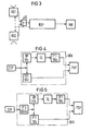
- Fig. 1 ein erfindungsgemäßes Mikrowellen-Einbruchmeldesystem im Blockschaltbild mit einem Radarsensor, einem Radarsignalprozessor und einem Mikrorechner,
- Fig. 2 ein Pulsdiagramm,
- Fig. 3 ein Mikrowellen-Einbruchmeldesystem mit zwei Radarsensoren im Blockschaltbild,
- Fig. 4 ein Ausführungsbeispiel einer Digitalfilteranordnung im Blockschaltbild,
- Fig. 5 ein weiteres Ausführungsbeispiel einer Digitalfilteranordnung im Blockschaltbild und
- Fig. 6 eine Anordnung eines Mikrowellen-Einbruchmeldesystems an einem Schutzzaun, schematisch dargestellt.
- 1 shows a microwave intrusion detection system according to the invention in a block diagram with a radar sensor, a radar signal processor and a microcomputer,
- 2 shows a pulse diagram,
- 3 shows a microwave intrusion detection system with two radar sensors in a block diagram,
- 4 shows an exemplary embodiment of a digital filter arrangement in a block diagram,
- Fig. 5 shows another embodiment of a digital filter arrangement in the block diagram and
- Fig. 6 shows an arrangement of a microwave intrusion detection system on a protective fence, shown schematically.
In Fig. 1 ist der Radarsensor RS mit der Auswerteeinrichtung AWE im Blockschaltbild gezeigt. Der Radarsensor RS sendet in bestimmten Zeitabständen periodisch einen kurzen Sendeimpuls, beispielsweise von 80 nsec Dauer, aus. Je nach Entfernung der Objekte treffen die reflektierten Sendesignale als Echosignale zeitlich verzögert im Empfangsteil des Radarsensors ein. Diese Radar- empfangssignale werden in der Auswerteeinrichtung AWE einem Analog-Digital-Wandler AD zugeführt, der die digitalisierten Signale über einen Zwischenspeicher ZSP an eine digitale Filteranordnung DFA gibt. Eine zentrale Taktstation, ein Taktgenerator TG, steuert dabei den Analog Digital-Wandler AD, d. h. er liefert die benötigte Abtastfrequenz, sowie den Sendeimpulstrigger an den Radarsensor RS. Außerdem wird eine im Radarsignalprozessor RSP angeordnete Programmablaufsteuereinrichtung PAS mit der nötigen Taktfrequenz des Taktgenerators TG versorgt. Die Programmablaufsteuerung PAS steuert den Zwischenspeicher ZSP und die digitale Filteranordnung DFA. Die mittels der digitalen Filteranordnung DFA reduzierte Datenrate der Radarempfangssignale wird einem Pufferspeicher PSP zugeführt, von dort gelangen sie an den Mikrorechner MR, der nach bestimmten Kriterien eine Auswertung vornimmt, um entsprechende Alarmsignale abzuleiten. Die Ausgabe der Daten vom Pufferspeicher PSP kann dabei in Abhängigkeit vom Radarsensor RS gesteuert werden. Die Programmablaufsteuereinrichtung PAS steuert den Mikrorechner MR. Die Funktionsweise wird im folgenden im Zusammenhang mit der Fig. 2 erläutert.1 shows the radar sensor RS with the evaluation device AWE in the block diagram. The radar sensor RS periodically emits a short transmission pulse, for example of 80 nsec duration, at certain time intervals. Depending on the distance of the objects, the reflected transmission signals arrive as delayed echo signals in the receiving part of the radar sensor. These radar reception signals are fed in the evaluation device AWE to an analog-to-digital converter AD, which outputs the digitized signals to a digital filter arrangement DFA via an intermediate memory ZSP. A central clock station, a clock generator TG, controls the analog digital converter AD, i. H. it supplies the required sampling frequency and the transmit pulse trigger to the radar sensor RS. In addition, a program sequence control device PAS arranged in the radar signal processor RSP is supplied with the necessary clock frequency of the clock generator TG. The program sequence control PAS controls the intermediate storage ZSP and the digital filter arrangement DFA. The data rate of the radar reception signals reduced by means of the digital filter arrangement DFA is fed to a buffer memory PSP, from there they arrive at the microcomputer MR, which carries out an evaluation according to certain criteria in order to derive corresponding alarm signals. The output of the data from the buffer memory PSP can be controlled depending on the radar sensor RS. The program sequence control device PAS controls the microcomputer MR. The mode of operation is explained below in connection with FIG. 2.
In Fig. 2 ist ein Pulsdiagramm der Sende- und Empfangssignale dargestellt. Das vom Radarsensor (RS) abgegebene Radarsendesignal RSSm mit einer Impulsdauer TS von 80 nsec erreicht zum Zeitpunkt t0 sein Maximum. Die reflektierten Radarsendesignale werden zeitlich nacheinander als Echosignale empfangen und sind mit RESm (Radarempfangssignal) bezeichnet und mit einer Abtastfrequenz von beispielsweise 12,5 MHz und einer Auflösung von 7 Bit digitalisiert. Dadurch werden z.B. 64 Zeitschlitze ZS1 bis ZSn gebildet (n = 64) mit einer Zeitdauer TZ von jeweils 80 nsec. Das nächstfolgende Radarsensorsignal RSS (m + 1) erfolgt erst nach einer Zeit von 312 psec. Die Empfangszeit für die Radarempfangssignale beträgt etwa 10 µsec, was einer Entfernung von ca. 1,5 km entspricht. In der nachfolgenden Totzeit bis zum Abstrahlen des nächsten Sendeimpulses bleibt genügend Zeit zur Verarbeitung der empfangenen Signale. Einer Empfangszeit von beispielsweise 5,12 µsec entsprechen 64 Zeitschlitzen (n = 64) von jeweils 80 nsec. Dadurch werden 64 Entfernungstore ET gebildet, die jeweils 12 Meter aufweisen, so daß mit einem Radarsensor eine Strecke von 768 Metern überwacht werden kann. In Fig. 2 ist unterhalb des Pulsdiagramms die Zeit t in µsec dargestellt, und darunter ist entsprechend die Bildung der Entfernungstore ET1 bis ETn als Zielentfernung ZE in Metern (m) dargestellt.2 shows a pulse diagram of the transmit and receive signals. The radar transmission signal RSSm emitted by the radar sensor (RS) with a pulse duration TS of 80 nsec reaches its maximum at time t0. The reflected radar transmission signals are received one after the other as echo signals and are designated RESm (radar reception signal) and digitized with a sampling frequency of, for example, 12.5 MHz and a resolution of 7 bits. This will e.g. 64 time slots ZS1 to ZSn formed (n = 64) with a time duration TZ of 80 nsec each. The next radar sensor signal RSS (m + 1) takes place after a time of 312 psec. The reception time for the radar reception signals is approximately 10 µsec, which corresponds to a distance of approximately 1.5 km. In the subsequent dead time until the next transmission pulse is emitted, there is sufficient time to process the received signals. A reception time of, for example, 5.12 microseconds corresponds to 64 time slots (n = 64) of 80 nsec each. As a result, 64 distance gates ET are formed, each having a length of 12 meters, so that a distance of 768 meters can be monitored with a radar sensor. 2 shows the time t in microseconds below the pulse diagram, and below this the formation of the distance gates ET1 to ETn is shown as the target distance ZE in meters (m).
Die Aufgabe des Signalprozessors besteht nun darin, einerseits die Empfangssignale zu digitalisieren und andererseits die hohe Datenrate der Empfangssignale auf eine Datenrate zu reduzieren, die vom nachgeschalteten Mikrorechner verarbeitet werden kann. Dabei sollen keine großen Verluste am SignallRauschverhältnis entstehen. Mit Hilfe der digitalen Filteranordnung werden die Werte von beispielsweise 256 aufeinanderfolgenden Echosignalen zusammengefaßt, so daß die Ausgabe der Meßdaten für die einzelnen Entfernungstore mit einer Wiederholrate von 256 mal 312.gsec erfolgen kann. Die Reduzierung der vom Radarsensor gelieferten Datenrate von ca. 100 Mbit pro Sekunde auf beispielsweise 20 Kbit pro Sekunde geschieht auf zweifache weise. Die erste Reduzierung erfolgt durch Zwischenspeichern der in dem kurzen Empfangszeitraum von ca. 10 µs digitalisierten Echosignale im Zwischenspeicher ZSP und der nachfolgenden Abarbeitung bis zum nächsten Sendeimpuls (Sendeimpulsabstand 312 ps). Die zweite, die wesentliche Reduzierung erfolgt in der digitalen Filteranordnung DFA, indem von mehreren aufeinanderfolgenden Daten eines jeweiligen Empfangstores eine Art Mittelwert gebildet wird, wobei die Anzahl (m) der aufeinanderfolgenden Daten von der Zeitkonstante des Filters abhängt. Im Grunde genommen werden die aufeinanderfolgenden Daten aufintegriert und der dadurch gewonnene Mittelwert an den Pufferspeicher abgegeben.The signal processor now has the task of digitizing the received signals on the one hand and reducing the high data rate of the received signals to a data rate that can be processed by the downstream microcomputer. There should be no major losses in the signal-to-noise ratio. With the aid of the digital filter arrangement, the values of, for example, 256 successive echo signals are combined, so that the measurement data for the individual distance gates can be output at a repetition rate of 256 times 312.gsec. The data rate supplied by the radar sensor is reduced from approximately 100 Mbit per second to, for example, 20 Kbit per second in two ways. The first reduction takes place by temporarily storing the echo signals digitized in the short reception period of approximately 10 μs in the intermediate memory ZSP and the subsequent processing until the next transmit pulse (transmit
In Fig. 3 sind zwei Radarsensoren RS1 und RS2 dargestellt, die über eine steuerbare Umschalteinrichtung US abwechselnd an den Radarsignalprozessor RSP angeschlossen werden. Die Funktionsweise ist dann folgende. Der Radarsensor 1 gibt einen ersten Sendeimpuls, ein Radarsignal (RSS) ab. In der Zeit von t=0 bis t=5,12gsec werden die Echosignale mit der Abtastfrequenz von beispielsweise 12,5 MHz digitalisiert und zwischengespeichert, so daß 64 Empfangstore gebildet werden. Nach der Zeit t von 5,12 J.1sec wird vom zweiten Radarsensor RS2 ein Sendeimpuls abgestrahlt, die Empfangssignale werden innerhalb der Zeit t=5,12 bis 10,24 J.1sec digitalisiert und zwischengespeichert, so daß weitere Empfangstore 64 bis 127 gebildet werden. Insgesamt werden also 2 x 64 Empfangstore a 12 Meter gebildet, das entspricht einer Überwachungsstrecke von 2 x 768 Metern. Die beiden Radarsensoren können dabei am Schutzzaun Rücken an Rücken angeordnet sein und somit insgesamt eine Überwachungsstrecke von annähernd 800 Metern überwachen. Mit dieser Anordnung kann aber auch eine geknickte Überwachungsstrecke überwacht werden, beispielsweise an einer Ecke des zu überwachenden Areals, so daß die beiden Radarsensoren in einem bestimmten Winkel, z.B. im 90°-Winkel zueinander angeordnet sind.3 shows two radar sensors RS1 and RS2, which are alternately connected to the radar signal processor RSP via a controllable switchover device US. The mode of operation is then as follows. The
In Fig. 4 ist eine digitale Filteranordnung DFA dargestellt, die die digitalisierten Empfangssignale vom Zwischenspeicher ZSP erhält. Die digitale Filteranordnung DFA weist zwei Filterzweige auf, d.h. die Daten werden auf zwei Zweige aufgeteilt. Im ersten Zweig ist ein Hochpaßfilter HP mit einer Grenzfrequenz von 5 Hz angeordnet, dessen Ausgang auf einen Gleichrichter GL führt. Diesem nachgeschaltet ist ein weiteres Filter angeordnet, nämlich ein Tiefpaßfilter TP1 mit einer Grenzfrequenz von 5 Hz, dessen Ausgang auf den der digitalen Filteranordnung DFA nachgeschalteten Pufferspeicher PSP führt. Der zweite Filterzweig weist ebenfalls ein Tiefpaßfilter TP2 mit einer Grenzfrequenz von 5 Hz auf.FIG. 4 shows a digital filter arrangement DFA which receives the digitized received signals from the buffer store ZSP. The digital filter arrangement DFA has two filter branches, i.e. the data is divided into two branches. A high-pass filter HP with a cut-off frequency of 5 Hz is arranged in the first branch, the output of which leads to a rectifier GL. A further filter is arranged downstream of this, namely a low-pass filter TP1 with a cut-off frequency of 5 Hz, the output of which leads to the buffer memory PSP connected downstream of the digital filter arrangement DFA. The second filter branch also has a low-pass filter TP2 with a cut-off frequency of 5 Hz.
In der Fig. 5 ist eine digitale Filteranordnung DFA dargestellt, die ähnlich der digitalen Filteranordnung DFA der Fig. 4 aufgebaut ist; jedoch ist zwischen den beiden Filterzweigen und dem Zwischenspeicher ZSP ein weiteres Filter angeordnet, nämlich ein drittes Tiefpaßfilter TP3 mit einer Grenzfrequenz von 100 Hz. Die digitalisierten Radarempfangssignale werden aus dem Zwischen- speicher ZSP dem Tiefpaßfilter TP3 zugeführt. Hier werden alle Schwebungsfrequenzen über 100 Hz, die einer Bewegungsgeschwindigkeit eines Eindringlings von 1,6 Meter pro Sekunde entsprechen, geschwächt. Es folgt dann eine Aufteilung in zwei Wege. Die Empfangsechos, d.h. die Radarempfangssignale von schnell beweglichen Objekten, z. B. einem laufenden Eindringling, werden vom ersten Filterzweig erfaßt. Ein laufender Eindringling weist erfahrungsgemäß große Amplituden mit einer Dopplerfrequenz von 5 bis 150 Hz auf. Diese Echosignale durchlaufen das Hochpaßfilter HP mit einer Grenzfrequenz von 5 Hz, werden gleichgerichtet (Gleichrichterschaltung GL) und werden nochmals mit 5 Hz Tiefpaß gefiltert (TP1), um eine Mittelwertbildung über ca. 300 Empfangsperioden durchzuführen. Der zweite Filterweg dient zur Erfassung von sich langsam bewegenden Objekten. Man kann davon ausgehen, daß ein intelligenter Eindringling versucht, kriechend oder rollend durch sehr langsame Bewegung einzudringen. Erfahrungsgemäß führt dies zu kleinen Amplituden mit einer Dopplerfrequenz von 0 bis 5 Hz. Diese Echosignale durchlaufen den zweiten Filterweg mit dem Tiefpaß TP2 mit der Grenzfrequenz von 5 Hz.FIG. 5 shows a digital filter arrangement DFA, which is constructed similarly to the digital filter arrangement DFA of FIG. 4; however, a further filter is arranged between the two filter branches and the buffer store ZSP, namely a third low-pass filter TP3 with a cut-off frequency of 100 Hz. The digitized radar reception signals are fed from the buffer store ZSP to the low-pass filter TP3. Here, all beat frequencies above 100 Hz, which correspond to an intruder's moving speed of 1.6 meters per second, are weakened. This is then divided into two ways. The reception echoes, i.e. the radar reception signals of fast moving objects, e.g. B. an ongoing intruder, are detected by the first filter branch. Experience has shown that a running intruder has large amplitudes with a Doppler frequency of 5 to 150 Hz. These echo signals pass through the high-pass filter HP with a cut-off frequency of 5 Hz, are rectified (rectifier circuit GL) and are filtered again with 5 Hz low-pass filter (TP1) in order to carry out averaging over approx. 300 reception periods. The second filter path is used to detect slowly moving objects. It can be assumed that an intelligent intruder tries to penetrate by creeping or rolling through very slow movement. Experience has shown that this leads to small amplitudes with a Doppler frequency of 0 to 5 Hz. These echo signals pass through the second filter path with the low-pass filter TP2 with the cut-off frequency of 5 Hz.
Für jedes Entfernungstor stehen also am Ausgang der digitalen Filteranordnung DFA zwei Signale zur Verfügung, einmal für schnellbewegliche Ziele für 128 Entfernungstore mit 5 Hz Bandbreite und zum anderen Mal für langsam bewegliche Ziele für 128 Entfernungstore mit 5 Hz Bandbreite. Um Verluste bei der Weiterverarbeitung zu vermeiden, werden diese Signale zweckmäßigerweise in Zeitabständen von beispielsweise 312 µs abgetastet, d.h. diese Signale werden im Rhythmus des Sendeimpulstriggers ausgegeben (In Fig. 1 mit der gestrichelten Linie angedeutet, die vom Radarsensor RS zum Pufferspeicher PSP führt). Hierzu wird mit jedem neuen Sendeimpuls eine der 256 Informationen übergeben, wobei eine Datenrate von 3200/256 = 12,5 Hz entsteht. 3200 ist die Pulsfrequenz (PRF = Pulsreceptionfrequency) entsprechend einer Zeit von 312 usec von Sendeimpuls zu Sendeimpuls.For each range gate, two signals are therefore available at the output of the digital filter arrangement DFA, one for fast moving targets for 128 range gates with 5 Hz bandwidth and the other time for slow moving targets for 128 range gates with 5 Hz bandwidth. In order to avoid losses during further processing, these signals are expediently sampled at intervals of, for example, 312 µs, i.e. these signals are output in the rhythm of the transmit pulse trigger (indicated in FIG. 1 by the dashed line leading from the radar sensor RS to the buffer memory PSP). For this purpose, one of the 256 pieces of information is transferred with each new transmission pulse, resulting in a data rate of 3200/256 = 12.5 Hz. 3200 is the pulse frequency (PRF = pulse reception frequency) corresponding to a time of 312 usec from transmit pulse to transmit pulse.
In Fig. 6 ist eine mögliche Anordnung eines Radarsensors RS am Schutzzaun SZ dargestellt. Weist beispielsweise der Schutzzaun eine Höhe H (z. B. H = 10 m) auf, so kann der Radarsensor RS in der Höhe h von beispielsweise 5 Metern angeordnet werden. Dabei wird mit einem Halbwertswinkel von beispielsweise 1° oder weniger ein Antennenrichtdiagramm erzeugt, das parallel zum Schutzzaun SZ verläuft. Dabei kann ein Überwachungsabschnitt E von über 700 Metern überwacht werden. Dem Radarsensor RS sind der Radarsignalprozessor RSP und der Mikrorechner MR nachgeschaltet. Üblicherweise wird ein Radarsensor zwischen zwei Schutzzäunen innerhalb einer sterilen Zone zu deren Überwachung angeordnet.
- Bezugszeichenliste
- TG Taktgenerator
- SR Radarsensor
- RES Radar-Empfangssignale (reflektierte Sendesignale)
- AWE Auswerteeinrichtung
- PAS Programmablaufsteuereinrichtung
- RSP Radarsignalprozessor
- AD Analog/Digital-Wandler
- ZSP Zwischen-Speicher
- MR Mikrorechner
- DFA Digitalfilteranordnung
- PSP Pufferspeicher
- RSS Radar-Sendesignal
- TS Zeit eines Sendeimpulses (RSS), z.B. 80ns
- TZ Zeit eines Zeitschlitzes (ZS), z.B. 80ns
- ZS Zeitschlitz = Abtastzeit
- ET Entfernungstor = 1 Zeitschlitz
- ZE Zielentfernung
- TP Tiefpaß
- HP Hochpaß
- GL Gleichrichter
- Reference symbol list
- TG clock generator
- SR radar sensor
- RES radar reception signals (reflected transmission signals)
- AWE evaluation device
- PAS program sequence control device
- RSP radar signal processor
- AD analog / digital converter
- ZSP cache
- MR microcomputer
- DFA digital filter arrangement
- PSP buffer storage
- RSS radar broadcast signal
- TS time of a transmission pulse (RSS), eg 80ns
- TZ time of a time slot (ZS), eg 80ns
- ZS time slot = sampling time
- ET distance gate = 1 time slot
- ZE target distance
- TP low pass
- HP high pass
- GL rectifier
Claims (6)
Priority Applications (1)
| Application Number | Priority Date | Filing Date | Title |
|---|---|---|---|
| AT84115743T ATE45045T1 (en) | 1984-04-13 | 1984-12-18 | MICROWAVE INTRUDER DETECTION SYSTEM. |
Applications Claiming Priority (2)
| Application Number | Priority Date | Filing Date | Title |
|---|---|---|---|
| DE3414023 | 1984-04-13 | ||
| DE3414023 | 1984-04-13 |
Publications (2)
| Publication Number | Publication Date |
|---|---|
| EP0158731A1 EP0158731A1 (en) | 1985-10-23 |
| EP0158731B1 true EP0158731B1 (en) | 1989-07-26 |
Family
ID=6233530
Family Applications (1)
| Application Number | Title | Priority Date | Filing Date |
|---|---|---|---|
| EP84115743A Expired EP0158731B1 (en) | 1984-04-13 | 1984-12-18 | Microwave intrusion detection system |
Country Status (3)
| Country | Link |
|---|---|
| EP (1) | EP0158731B1 (en) |
| AT (1) | ATE45045T1 (en) |
| DE (1) | DE3479159D1 (en) |
Families Citing this family (3)
| Publication number | Priority date | Publication date | Assignee | Title |
|---|---|---|---|---|
| EP0787998A3 (en) * | 1996-02-02 | 1998-05-20 | f+g megamos Sicherheitselektronik GmbH | Microwave sensor system for the monitoring of spaces |
| DE19646462A1 (en) * | 1996-11-11 | 1998-05-14 | Micas Elektronik Gmbh U Co Kg | Intrusion monitoring system in passage opening especially doorway |
| DE10125311A1 (en) * | 2001-05-23 | 2002-11-28 | Delphi Tech Inc | Monitoring system, for motor vehicles, detects faults using radar signals reflected at defined smaller distance or spherical shell compared to incursion detection reflection distance |
Family Cites Families (3)
| Publication number | Priority date | Publication date | Assignee | Title |
|---|---|---|---|---|
| DE1934723C1 (en) * | 1969-07-09 | 1978-04-27 | Siemens Ag | Pulse Doppler radar device with a device for suppressing interference |
| DE2450732C3 (en) * | 1974-10-25 | 1979-01-04 | Licentia Patent-Verwaltungs-Gmbh, 6000 Frankfurt | Monitoring system with a sensor that works according to the reflection method and as a barrier |
| DE3128990A1 (en) * | 1981-07-22 | 1983-02-10 | Westinghouse Electric Corp., 15222 Pittsburgh, Pa. | Method for processing signals of a Pulse Doppler radar system and a device for carrying out the method |
-
1984
- 1984-12-18 EP EP84115743A patent/EP0158731B1/en not_active Expired
- 1984-12-18 AT AT84115743T patent/ATE45045T1/en not_active IP Right Cessation
- 1984-12-18 DE DE8484115743T patent/DE3479159D1/en not_active Expired
Also Published As
| Publication number | Publication date |
|---|---|
| ATE45045T1 (en) | 1989-08-15 |
| DE3479159D1 (en) | 1989-08-31 |
| EP0158731A1 (en) | 1985-10-23 |
Similar Documents
| Publication | Publication Date | Title |
|---|---|---|
| EP3014297B1 (en) | Angle-resolving fmcw radar sensor | |
| DE10059673A1 (en) | Pulse radar method as well as pulse radar sensor and system | |
| DE3107444A1 (en) | "HIGH-RESOLUTION COHERENT PULSRADAR" | |
| DE2734998A1 (en) | DOPPLER RADAR SYSTEM AS A SAFETY DEVICE FOR VEHICLES | |
| DE19963006A1 (en) | Method to detect and evaluate objects near vehicle, involves determining speed and distance of target object within virtual barrier or range gate, whose length and distance from vehicle can be varied | |
| WO1996002859A1 (en) | Arrangement for detecting objects in a region to be monitored | |
| EP0157117A1 (en) | Testing device for an intrusion-signalling apparatus | |
| WO2006069924A1 (en) | Radar system for monitoring targets in different distance ranges | |
| DE3041465A1 (en) | A method in a tracking radar to attain a large unambiguous range for detected targets by means of radar pulses with high repetition frequency | |
| DE2308812A1 (en) | RADAR DEVICE | |
| EP3339876B1 (en) | Method for operating a radar system for preventing deception by third parties | |
| EP0158731B1 (en) | Microwave intrusion detection system | |
| EP0188757A1 (en) | Microwave intrusion alarm system | |
| EP4249938A2 (en) | Method and device for tracking objects, in particular moving objects, in the three-dimensional space of imaging radar sensors | |
| DE2045120C3 (en) | Pulse Doppler radar arrangement with several consecutive pulse repetition frequencies to eliminate speed ambiguities | |
| EP0616232B1 (en) | Traffic radar system | |
| EP0497093A2 (en) | Method and device for detecting vehicles in road traffic to control a traffic signalling device | |
| EP0023625B1 (en) | Alarm system for intrusion detection of an object moving in the proximity of an object to be protected | |
| DE1812999A1 (en) | Collision protection system, especially for aircraft | |
| DE2440742B2 (en) | Device for the elimination of interference and fixed signals | |
| DE4027972A1 (en) | DEVICE AND METHOD FOR TELEMETRICALLY DETERMINING A DISTANCE AND APPLICATION TO A RADAR PROBE FOR DETERMINING THE TOPOGRAPHIC MAP OF THE SURVEYING SURFACE IN A SHAFT OVEN | |
| EP0096883A2 (en) | Pulse Doppler radar with a pulse length discriminator | |
| DE3129841C2 (en) | "Device for giving an alarm in the event of unauthorized entry into a protection zone along a border line" | |
| DE3818813C1 (en) | Sensor combination system for clarification of the air situation | |
| DE3502399C1 (en) | Electronic device for countermeasures in a coherent pulse radar receiver |
Legal Events
| Date | Code | Title | Description |
|---|---|---|---|
| PUAI | Public reference made under article 153(3) epc to a published international application that has entered the european phase |
Free format text: ORIGINAL CODE: 0009012 |
|
| 17P | Request for examination filed |
Effective date: 19850102 |
|
| AK | Designated contracting states |
Designated state(s): AT BE CH DE FR GB IT LI NL SE |
|
| 17Q | First examination report despatched |
Effective date: 19871026 |
|
| GRAA | (expected) grant |
Free format text: ORIGINAL CODE: 0009210 |
|
| AK | Designated contracting states |
Kind code of ref document: B1 Designated state(s): AT BE CH DE FR GB IT LI NL SE |
|
| REF | Corresponds to: |
Ref document number: 45045 Country of ref document: AT Date of ref document: 19890815 Kind code of ref document: T |
|
| REF | Corresponds to: |
Ref document number: 3479159 Country of ref document: DE Date of ref document: 19890831 |
|
| ET | Fr: translation filed | ||
| ITF | It: translation for a ep patent filed |
Owner name: STUDIO JAUMANN |
|
| GBT | Gb: translation of ep patent filed (gb section 77(6)(a)/1977) | ||
| PLBE | No opposition filed within time limit |
Free format text: ORIGINAL CODE: 0009261 |
|
| STAA | Information on the status of an ep patent application or granted ep patent |
Free format text: STATUS: NO OPPOSITION FILED WITHIN TIME LIMIT |
|
| 26N | No opposition filed | ||
| ITTA | It: last paid annual fee | ||
| EAL | Se: european patent in force in sweden |
Ref document number: 84115743.1 |
|
| PGFP | Annual fee paid to national office [announced via postgrant information from national office to epo] |
Ref country code: CH Payment date: 19950317 Year of fee payment: 11 |
|
| PGFP | Annual fee paid to national office [announced via postgrant information from national office to epo] |
Ref country code: GB Payment date: 19951123 Year of fee payment: 12 |
|
| PGFP | Annual fee paid to national office [announced via postgrant information from national office to epo] |
Ref country code: AT Payment date: 19951129 Year of fee payment: 12 |
|
| PGFP | Annual fee paid to national office [announced via postgrant information from national office to epo] |
Ref country code: BE Payment date: 19951213 Year of fee payment: 12 |
|
| PGFP | Annual fee paid to national office [announced via postgrant information from national office to epo] |
Ref country code: SE Payment date: 19951221 Year of fee payment: 12 |
|
| PGFP | Annual fee paid to national office [announced via postgrant information from national office to epo] |
Ref country code: FR Payment date: 19951226 Year of fee payment: 12 |
|
| PGFP | Annual fee paid to national office [announced via postgrant information from national office to epo] |
Ref country code: NL Payment date: 19951230 Year of fee payment: 12 |
|
| PG25 | Lapsed in a contracting state [announced via postgrant information from national office to epo] |
Ref country code: LI Effective date: 19951231 Ref country code: CH Effective date: 19951231 |
|
| PGFP | Annual fee paid to national office [announced via postgrant information from national office to epo] |
Ref country code: DE Payment date: 19960219 Year of fee payment: 12 |
|
| REG | Reference to a national code |
Ref country code: CH Ref legal event code: PL |
|
| PG25 | Lapsed in a contracting state [announced via postgrant information from national office to epo] |
Ref country code: GB Effective date: 19961218 Ref country code: AT Effective date: 19961218 |
|
| PG25 | Lapsed in a contracting state [announced via postgrant information from national office to epo] |
Ref country code: SE Effective date: 19961219 |
|
| PG25 | Lapsed in a contracting state [announced via postgrant information from national office to epo] |
Ref country code: BE Effective date: 19961231 |
|
| BERE | Be: lapsed |
Owner name: SIEMENS A.G. BERLIN UND MUNCHEN Effective date: 19961231 |
|
| PG25 | Lapsed in a contracting state [announced via postgrant information from national office to epo] |
Ref country code: NL Effective date: 19970701 |
|
| GBPC | Gb: european patent ceased through non-payment of renewal fee |
Effective date: 19961218 |
|
| PG25 | Lapsed in a contracting state [announced via postgrant information from national office to epo] |
Ref country code: FR Effective date: 19970829 |
|
| NLV4 | Nl: lapsed or anulled due to non-payment of the annual fee |
Effective date: 19970701 |
|
| PG25 | Lapsed in a contracting state [announced via postgrant information from national office to epo] |
Ref country code: DE Effective date: 19970902 |
|
| EUG | Se: european patent has lapsed |
Ref document number: 84115743.1 |
|
| REG | Reference to a national code |
Ref country code: FR Ref legal event code: ST |