EP0158728A1 - Generation of anaerobic or microaerophilic atmosphere - Google Patents
Generation of anaerobic or microaerophilic atmosphere Download PDFInfo
- Publication number
- EP0158728A1 EP0158728A1 EP84115555A EP84115555A EP0158728A1 EP 0158728 A1 EP0158728 A1 EP 0158728A1 EP 84115555 A EP84115555 A EP 84115555A EP 84115555 A EP84115555 A EP 84115555A EP 0158728 A1 EP0158728 A1 EP 0158728A1
- Authority
- EP
- European Patent Office
- Prior art keywords
- package
- compartment
- accordance
- envelope
- catalyst
- Prior art date
- Legal status (The legal status is an assumption and is not a legal conclusion. Google has not performed a legal analysis and makes no representation as to the accuracy of the status listed.)
- Granted
Links
Images


Classifications
-
- C—CHEMISTRY; METALLURGY
- C12—BIOCHEMISTRY; BEER; SPIRITS; WINE; VINEGAR; MICROBIOLOGY; ENZYMOLOGY; MUTATION OR GENETIC ENGINEERING
- C12M—APPARATUS FOR ENZYMOLOGY OR MICROBIOLOGY; APPARATUS FOR CULTURING MICROORGANISMS FOR PRODUCING BIOMASS, FOR GROWING CELLS OR FOR OBTAINING FERMENTATION OR METABOLIC PRODUCTS, i.e. BIOREACTORS OR FERMENTERS
- C12M41/00—Means for regulation, monitoring, measurement or control, e.g. flow regulation
- C12M41/30—Means for regulation, monitoring, measurement or control, e.g. flow regulation of concentration
- C12M41/34—Means for regulation, monitoring, measurement or control, e.g. flow regulation of concentration of gas
-
- C—CHEMISTRY; METALLURGY
- C12—BIOCHEMISTRY; BEER; SPIRITS; WINE; VINEGAR; MICROBIOLOGY; ENZYMOLOGY; MUTATION OR GENETIC ENGINEERING
- C12M—APPARATUS FOR ENZYMOLOGY OR MICROBIOLOGY; APPARATUS FOR CULTURING MICROORGANISMS FOR PRODUCING BIOMASS, FOR GROWING CELLS OR FOR OBTAINING FERMENTATION OR METABOLIC PRODUCTS, i.e. BIOREACTORS OR FERMENTERS
- C12M29/00—Means for introduction, extraction or recirculation of materials, e.g. pumps
-
- Y—GENERAL TAGGING OF NEW TECHNOLOGICAL DEVELOPMENTS; GENERAL TAGGING OF CROSS-SECTIONAL TECHNOLOGIES SPANNING OVER SEVERAL SECTIONS OF THE IPC; TECHNICAL SUBJECTS COVERED BY FORMER USPC CROSS-REFERENCE ART COLLECTIONS [XRACs] AND DIGESTS
- Y10—TECHNICAL SUBJECTS COVERED BY FORMER USPC
- Y10S—TECHNICAL SUBJECTS COVERED BY FORMER USPC CROSS-REFERENCE ART COLLECTIONS [XRACs] AND DIGESTS
- Y10S435/00—Chemistry: molecular biology and microbiology
- Y10S435/801—Anerobic cultivation
Definitions
- the present invention relates generally to an apparatus and method for the generation of an anaerobic or microaerophilic atmosphere which is conducive to the growth of certain microorganisms.
- microorganisms require an aerobic atmosphere for growth ' , others require an anaerobic atmosphere, and still others require a microaerophilic atmosphere in which the oxygen level is between aerobic and anaerobic. In addition, some microorganisms require specific levels of carbon dioxide for growth.
- United States Patent No. 4,347,222 to Beall discloses disposition of the catalyst in one receptacle of a unitary apparatus. This apparatus requires means for puncturing seals between several of the receptacles. The puncture means is supplied by a device which is separate from the gas generating apparatus or as part of a mated container.
- United States Patent No. 4,013,422 to Spinner discloses a container having a material for generating a reducing gas, such as hydrogen, for reaction, in the presence of a catalyst, with oxygen.
- the Spinner apparatus uses an exposed catalyst pellet with no provision for heat removal.
- it relies on the breaking of an ampoule containing a liquid and thereby instantaneous release of the liquid into contact with the material for generating the reducing gas.
- no means are provided for controlling the rate at which the contact is made.
- contact at a slow and controlled rate is essential for accurate attainment of pre-determined final oxygen levels, particularly in those cases where it is desired to reduce, but not eliminate, the oxygen in the atmosphere.
- U.S. Pat. No. 4,287,306 to Brewer describes a further apparatus for generating anaerobic atmospheres.
- a flexible sealed package is provided with a catalyst coated onto the exterior surface of the package for use in catalyzing the reaction between oxygen outside the package and hydrogen generated within the package.
- This apparatus like the Spinner apparatus, has the disadvantage of exposed active catalyst.
- United States Patent No. 4,289,855 to Whitley discloses a safety catalyst package designed to reduce the danger of flashing or explosion.
- the Whitley package encloses a catalyst within holes and folds in a metal foil net.
- the net which is inside of a container having holes for gas exchange, is composed of a heat conducting material, and thereby functions to remove heat from the catalyst vicinity.
- the Whitley disclosure is of a safety catalyst package only., and makes no provision for supply of hydrogen.
- a package for use in an anaerobic jar and specifically designed for attainment of a microaerophilic atmosphere, is disclosed in United States Patent 4,377,554 to Johnson.
- the Johnson invention relies on control of "wetover” and “condensation” times for successful generation of microaerophilic atmospheres, and uses conventional exposed catalysts attached either to the outside of the package or to the lid of the jar.
- a cardboard package for use in generating an anaerobic atmosphere is commercially available from the BBL Microbiology Systems Division of Becton Dickinson Company.
- This package includes a catalyst chamber mounted in the side of the box.
- the catalyst chamber is porous on both sides to permit generated hydrogen to flow through the chamber and thus react with the catalyst.
- a package for removing all or part of the oxygen in a gaseous mixture includes a metallic foil envelope having a plurality of internal compartments.
- One compartment contains a material to generate hydrogen upon reaction with water.
- Another compartment contains a material to catalyze the reaction between the hydrogen and oxygen.
- Another compartment is adapted to receive water.
- the catalyst containing compartment has at least one opening in its outside wall to provide gas communication between the compartment and the atmosphere external to the envelope.
- a layer of porous thermostable material is positioned over the holes on the inside of the catalyst containing compartment.
- the catalyst containing compartment is additionally provided with a sealed cover on the inside of the compartment to separate the compartment from the inside of the envelope.
- the water receiving compartment is positioned over the catalyst containing compartment so that, when the frangible seal has been broken and water has been added, the water is above the catalyst and separated therefrom by the sealed cover.
- the water thus serves as a heat sink to conduct heat away from the catalyst during use.
- the water receiving and hydrogen generating compartments are in fluid communication through a channel provided with fluid transfer means.
- the fluid transfer means may be a wick prepared from any suitable material chosen such that the water" passes from the water receiving compartment into the hydrogen generating compartment at a pre-determined rate.
- a carbon dioxide generating composition forumulated in a manner to generate carbon dioxide and provide an acidic pH whereby, when used in a gas generating package along with a hydrogen generator, acidic to neutral pH conditions are maintained to prevent carbon dioxide absorption which may occur under alkaline conditions.
- one or more indicators attached to the outside of the foil package which show oxygen and carbon dioxide levels in the atmosphere.
- an independent catalyst compartment is provided which is not associated or in combination in the same package with gas generating means.
- a device for removing a pre-determined amount of oxygen from a gaseous atmosphere comprised of a package in the form of an envelope 10.
- Envelope 10 is made of a suitable material which is impervious to the atmosphere and moisture, and which is inert to materials contained within the package and gases generated therein and which is not destroyed by the heat of reaction released during use of the package, as hereinafter described.
- the envelope 10 may be formed of a metallic foil, such as aluminum, which may be coated on its inner surface with a thermoplastic material, such as polyethylene or a polymer formed of vinyl chloride.
- the envelope 10 may be formed from two panels suitably secured together around the edges by heat sealing.
- the envelope 10 is placed into container 32 having a lid 33 which forms a gas tight seal when the bracket 34 is tightened by the screw 35.
- the plated culture media in petri dishes 105 requiring a predetermined level of oxygen in the atmosphere are also placed in the container 36 prior to sealing the container.
- the closed container has a known volume of air and hence a known volume of oxygen. The volume of the package and a given number of petri dishes is also known and is accounted for in calculating the stoichiometric amount of hydrogen generating material required to reduce the atmosphere to the predetermined level of oxygen.
- the interior of the envelope is divided into a first gas generating compartment 11 and a second liquid-receiving compartment 12 by a suitable partition 20 which is formed, for example, by heat sealing when the top and bottom panels of the envelope are joined.
- the compartment 11 includes gas generating material in the form of a tablet 13, which includes materials capable of generating hydrogen and, optionally a tablet 14, which includes materials capable of generating carbon dioxide.
- the hydrogen generating material is used in excess when an anaerobic atmosphere is desired.
- sodium borohydride is used as the hydrogen generating material, about 0.9 gm is used to provide an anaerobic atmosphere in a 2.5 liter container.
- sodium borohydride When sodium borohydride is used to generate a microaerophilic atmosphere in a 2.5 liter container, about 0.15 to about 0.4 gm, preferably from about 0.20 gm to about 0.35 gm is used to remove from about 20 to about 80 percent of the oxygen present.
- the interior compartments 11 and 12 are in internal fluid and gas flow communication with each other through a channel in the portion 20 at the bottom of the envelope.
- the top of envelope is considered to be that end of the envelope wherein water is introduced.
- the bottom of the envelope is the other end.
- the channel is pr-ovided with controlled transfer means, such as the use of a wick 15 (shown in phantom outline in Fig. 1 and Fig. 2).
- the wick 15 is capable of permitting both liquid flow betwwen compartments 11 and 12 at a controlled rate as described in U.S. Patent No. 4,377,554, the subject matter of which is incorporated herein by reference.
- the wick 15 extends through the partition 20 into each of the compartments 11 and 12.
- Suitable, porous materials for use as wick 15 are filter paper, blotting paper, cotton twill, etc.
- a preferred wick material is filter paper having the designation Whatman #4. It should be understood that although the wick is shown as being a single sheet, it may be divided into two or more sheets.
- the partition 20 terminates before the top of the package whereby the compartments are in communication with each other through gap 25 above the partition.
- the package is designed to be used in a manner such that liquid introduced into compartment 12 does not reach gap 25 whereby only gas flow communication between compartments 11 and 12 occurs through gap 25 at the top of the envelope.
- a separate catalyst compartment 31 is provided within envelope 10.
- the panel in which the catalyst compartment is formed will be referred to as the "bottom” panel.
- the other panel which is mated with and sealed to bottom panel to complete formation of the envelope, is referred to as the "top” panel.
- Fig. 4 shows compartment 31, which may be any shape, formed as a cavity in bottom panel 30 of envelope 10.
- the portion, 32,.of bottom panel 30 which forms the outside wall of the compartment 31 is cut to provide at least one hole 28 therein, leaving a residual flange portion 37 in the bottom of cavity.
- Hole 28 provides gas communication between catalyst 27 and the atmosphere external to envelope 10.
- Flash arrestor 29 is then secured to the flange 37 over hole 28 by any suitable means, such as by gluing the flash arrestor in place.
- Flash arrestor 29 may be of any suitable thermostable, porous material, such as fiberglass cloth, perforated metal foil or metal screening.
- the mesh size of flash arrestor 29 is preferably from about 100 to 300 American Standard Sieve Size, most preferably from about 180 to 220.
- Catalyst 27 is then placed in compartment 31 above flash arrestor 29.
- catalyst 27 is particularly shown in Fig. 6 as pellets, other forms of catalyst may be used, as, for example, spheres, cylinders,, powders, strips and the like.
- the catalyst may be used as such, or it may be supported on an inert carrier such as alumina, carbon, fiberglass cloth, synthetic polymer and glass tape.
- an inert carrier such as alumina, carbon, fiberglass cloth, synthetic polymer and glass tape.
- a variety of materials may be used as the catalyst, such as platinum, rhodium, ruthenium, iridium or; preferably, palladium.
- Compartment 31 is then sealed on the internal side of the bottom panel 30 by attachment of the cover 26.
- Cover 26 is prepared from a su-itable material, such as metallic foil and is sealed around its edge to bottom panel 30. Cover 26 thereby protects catalyst 27 from contact with water in water receiving compartment 12. The water, after being added to water receiving compartment 12, is positioned adjacent to the catalyst and serves as a heat sink to remove heat from catalyst 27.
- a second cover (not shown) is placed over hole 28 on the outside of bottom panel 30 to protect the catalyst from ambient moisture with the envelope 10 is used.
- the second cover is prepared from a suitable material, such as metallic foil and is releasably sealed around its edge to bottom panel 30.
- the second cover is preferably provided with a grasping portion so that the cover is easily grasped and removed by the user just before or after addition of water to water receiving compartment 12.
- FIG. 8 A further embodiment of the invention is shown in Figures 8 and 9.
- a unitary piece of flame arrestor 29 is mated with a backing material 38 in a manner so as to enclose a suitable amount of catalyst 27 and provide a catalyst unit 39.
- the backing material is prepared from a suitable material, such as metal foil, and is sealed around the edge of the flame arrestor 29 to provide the catalyst unit 39.
- the catalyst unit 39 may be placed in the cavity -forming compartment 31 in the same manner heretofore described for the loose catalyst.
- the backing material 38 of the catalyst unit 39 can be adhered to the outside of the bottom panel 30for the top panel of the envelope or can be adhered to the inside wall 32 of the anaerobic jar shown in Fig. 3.
- FIGs. 10-16 A further embodiment of the invention is drawn in Figs. 10-16.
- a panel 36 of suitable material, such as metal foil is provided with a catalyst cavity 37 and an indicator cavity 38.
- the bottom of catalyst cavity is cut to provide at least one opening (not shown).
- a flame arrestor 29 is secured to the flange surrounding the hole by any suitable means.
- An absorbent strip 39 capable of absorbing an indicator solution is placed in the indicator cavity 38.
- catalyst pellets 27 are placed in the catalyst cavity 39.
- An indicator solution is absorbed into the strip 39.
- a cover 40 of suitable material such as metal foil, is securely affixed over the catalyst cavity 37.
- a peelable cover 41 is releasably affixed over the indicator cavity 38.
- An adhering means 42 such as double sided adhesive tape, is provided in the space between cover 40 and peelable cover 41.
- FIG. 13 A top view of the completed catalyst and indicator envelope 50 is shown in Fig. 13.
- the cover 41 is peeled away from surface surrounding the indicator cavity 38, when the envelope is placed in use.
- the adhering means 42 is then used to affix the envelope to the inside wall of an anaerobic jar 43 as shown in Fig. 15. This exposes the catalyst to reaction with oxygen and hydrogen through the opening in the flame arrestor 29.
- the hydrogen is generated by a separate hydrogen generating means (ot shown) after the jar 43 is sealed.
- the indicator strip 39 is easily visible from outside the jar.
- a carbon dioxide generating composition if provided.
- the carbon dioxide generating composition includes a water soluble solid acid and a water soluble carbonate in amounts suitable for generating carbon dioxide and also for providing an acidic pH; in particular, a pH of less than 6 when dissolved in water.
- suitable acids there may be mentioned: citric, tartatic, ascorbic, succinic, malic, fumaric, lactic acids and the like.
- suitable carbonates there may be mentioned; sodium bicarbonate, sodium carbonate, potassium carbonate, sodium sesquicarbonate, etc.
- the preferred composition includes citric acid and sodium bicarbonate.
- composition is preferably employed in the form of a tablet in which suitable lubricants and binders are generally also employed. It is, however, to be understood that forms other than a tablet may be used.
- suitable lubricants and binders are generally also employed. It is, however, to be understood that forms other than a tablet may be used.
- the exact proportion of acid and carbonate will differ with the materials used. The selection of suitable amounts to provide the desired carbon dioxide concentration for culturing and the acidic pH is deemed to be within the scope of those skilled in the art from the teachings herein.
- an oxygen indicator is also applied to the exterior of package 10.
- Such an indicator may be coated or otherwise applied to the metallic foil, and such indicator, as particularly shown in Fig. 1 is in the form of three different indicators, generally indicated as 18, 19 and 21.
- the indicators may be of methylene blue, resazurin, and indigo carmine which respond to different levels of oxygen, or which have different oxidation-reduction potentials. The use of such indicators will indicate different levels of oxygen.
- a similar indicator for monitoring the level of carbon dioxide may also be applied to the external surface of the metallic foil and is generally indicated as 23. Although such indicators have been particularly shown as being printed as spots on the exterior of the package, it is to be- understood that the indicator may take other forms such as lettering or other designs.
- the package in one embodiment, forms an integral unit for providing a microaerophilic or anaerobic atmosphere in that the package includes the materials for generating hydrogen and carbon dioxide, as well as the catalyst for catalyzing the reaction between hydrogen and oxygen . and the indicators for indicating oxygen concentration and carbon dioxide concentration.
- the releasable cover is removed from the oustide of the compartment 31.
- the liquid . receiving compartment 12 is opened by cutting away or tearing a corner of the envelope 10 along a tear line, generally indicated as 22.
- a material capable of interacting with the gas generating materials in compartment 11, such as water, is introduced into compartment 12, and such water flows into compartment 11, preferably at a predetermined controlled volume and rate, and preferably through the wick 15.
- the tablets 13 and 14 Upon contact with water, the tablets 13 and 14 generate hydrogen and carbon dioxide, which flow from compartment 11 into compartment 12 through the wick 15 and/or through the open gap 25 and ultimately into the container in which the envelope has been placed.
- the hydrogen reacts with oxygen in such container, with such reaction being catalyzed by the catalyst 27 in catalyst compartment 31.
- oxygen levels are indicated by means of the indicators 18, 19 and 21 which are applied to the exterior of package 10.
- Carbon dioxide concentration is indicated by indicator 23 which is also applied to the exterior of the package.
- the following exemplifies a formulation to produce a microaerophilic atmosphere in accordance with the present invention, which includes a carbon dioxide generating tablet, a hydrogen generating tablet, a catalyst for the reaction between hydrogen and oxygen and oxygen indicators and carbon dioxide indicators applied to the exterior of the package.
- the package in accordance with the example is employed as a gas generator, with such gas generation being effected by the addition of 10 ml of water to the liquid receiving compartment.
- Citric Acid 1.850 gm Sodium Bicarbonate 0.960 gm
- the tablet includes suitable binder and lubricant; e.g.,0.1272 g talc and 0.531 g microcrystalline cellulose
- the tablet includes suitable binder and lubircants.
- the tablet can be coated with a water soluble gelatin to prevent decomposition.
- Indicator Mixture 1.2 g indicator base 5 mg methylene blue Weigh 1.2 g of dry indicator mixture with 0.333 g Gum of Tragacanth. Add 40 ml of water and boil. Cool, ready for use.
- Indicator Mixture 1.2 g Indicator base 5 mg indigo carmine Weigh 1.2 g of dry indicator mixture with 0.3425 g Gum of Tragacanth. Mix with 40 ml of water and boil. Cool, ready to use.
- Indicator Mixture 1.2 g Indicator base 5 mg of resazurin Weigh 1.2 g of dry indicator mixture with 0.3345 g Gum of Tragacanth. Add 40 ml of water and boil. Cool, ready for use.
- Example 1 In order to produce an anaerobic atmosphere in accordance with the present invention, Example 1 is repeated exactly except the hydrogen generating tablet includes 0.9 gm. of sodium borohydride.
- Two.panels of aluminum foil measuring 5.9 inches by 3.3 inches were coated on one surface each with a vinyl laminate.
- One of the panels has a circular cavity about 1/4 inch deep and about 1 inch in diameter in the position shown by reference numeral 31 of Fig. 1.
- a single hole about 3/4 inch in diameter was punched in the bottom of the cavity.
- a circular piece of 200 mesh fiberglass cloth one inch in diameter was sealed in the cavity over the hole and catalyst pellets were placed on the fiberglass cloth.
- a 1.5 inch square of aluminum foil was placed over the cavity and heat sealed to the panel bottom portion by a heat sealing apparatus.
- Hydrogen and carbon dioxide generating tablets and a rectangle of Whatman #4 filter paper measuring 3 inches by 1.2 inches were placed on the laminated surface of the bottom panel in the positions shown in Fig. 2.
- the two panels were mated with the laminated surfaces facing each other and were inserted into a heat sealing apparatus having mating platens in the configuration shown in shaded outline in Fig. 1.
- the platens were closed and the apparatus was activated to provide a pressure of 70 + 40 psig for 2-3 seconds and at a temperature of 250° - 325°F.
- a second cover was then releasably sealed over the hole on the exterior-side of the envelope.
- the indicators were applied to the exterior of the package as follows:
- a liquid other than water could be employed for generating the gas, and materials other than those particularly described could also be employed for generating gas.
- a tablet capable of generating acetylene could be employed instead of a hydrogen generating tablet.
- the tablet could be formulated for producing hydrogen in a manner other than as particularly described; e.g., hydrogen could be generated by another liquid, such as an acid; in particular, hydrochloric acid, although the use of water is preferred.
- the liquid for generating the gas upon contacting the tablet could be within the package in a separate compartment or ampoule.
Abstract
Description
- The present invention relates generally to an apparatus and method for the generation of an anaerobic or microaerophilic atmosphere which is conducive to the growth of certain microorganisms.
- It is well known that some microorganisms require an aerobic atmosphere for growth', others require an anaerobic atmosphere, and still others require a microaerophilic atmosphere in which the oxygen level is between aerobic and anaerobic. In addition, some microorganisms require specific levels of carbon dioxide for growth.
- The attainment of an aerobic atmosphere is relatively simple, in most cases merely requiring aeration of the culture media. Anaerobic conditions are more difficult to attain and the prior art contains many devices and processes for producing anaerobic atmospheres. U.S. Pat. No. 3,246,959, to Brewer discloses a device for generating such anaerobic atmospheres by generation of hydrogen for reaction with oxygen in the atmosphere of an anaerobic apparatus such as that.disclosed in United States Patent No. 3,483,089 to Brewer. The reaction between the hydrogen and oxygen is catalyzed by a platinum catalyst in the anaerobic apparatus.
- United States Patent No. 4,347,222 to Beall discloses disposition of the catalyst in one receptacle of a unitary apparatus. This apparatus requires means for puncturing seals between several of the receptacles. The puncture means is supplied by a device which is separate from the gas generating apparatus or as part of a mated container.
- The reaction between hydrogen and oxygen in the presence of a catalyst is strongly exothermic. Flashing, and even explosion, can occur at the catalyst surface, particularly if the catalyst is finely divided and no means are provided to dissipate the heat generated.
- United States Patent No. 4,013,422 to Spinner discloses a container having a material for generating a reducing gas, such as hydrogen, for reaction, in the presence of a catalyst, with oxygen. The Spinner apparatus, however, uses an exposed catalyst pellet with no provision for heat removal. In addition, it relies on the breaking of an ampoule containing a liquid and thereby instantaneous release of the liquid into contact with the material for generating the reducing gas. Thus no means are provided for controlling the rate at which the contact is made. Experience has shown that contact at a slow and controlled rate is essential for accurate attainment of pre-determined final oxygen levels, particularly in those cases where it is desired to reduce, but not eliminate, the oxygen in the atmosphere.
- U.S. Pat. No. 4,287,306 to Brewer describes a further apparatus for generating anaerobic atmospheres. In accordance with this patent, a flexible sealed package is provided with a catalyst coated onto the exterior surface of the package for use in catalyzing the reaction between oxygen outside the package and hydrogen generated within the package. This apparatus, like the Spinner apparatus, has the disadvantage of exposed active catalyst.
- United States Patent No. 4,289,855 to Whitley discloses a safety catalyst package designed to reduce the danger of flashing or explosion. The Whitley package encloses a catalyst within holes and folds in a metal foil net. The net, which is inside of a container having holes for gas exchange, is composed of a heat conducting material, and thereby functions to remove heat from the catalyst vicinity. The Whitley disclosure is of a safety catalyst package only., and makes no provision for supply of hydrogen.
- A package, for use in an anaerobic jar and specifically designed for attainment of a microaerophilic atmosphere, is disclosed in United States Patent 4,377,554 to Johnson. The Johnson invention relies on control of "wetover" and "condensation" times for successful generation of microaerophilic atmospheres, and uses conventional exposed catalysts attached either to the outside of the package or to the lid of the jar.
- A cardboard package for use in generating an anaerobic atmosphere is commercially available from the BBL Microbiology Systems Division of Becton Dickinson Company. This package includes a catalyst chamber mounted in the side of the box. The catalyst chamber is porous on both sides to permit generated hydrogen to flow through the chamber and thus react with the catalyst.
- In accordance with one embodiment of the present invention, there is provided a package for removing all or part of the oxygen in a gaseous mixture. The package includes a metallic foil envelope having a plurality of internal compartments. One compartment contains a material to generate hydrogen upon reaction with water. Another compartment contains a material to catalyze the reaction between the hydrogen and oxygen. Another compartment is adapted to receive water.
- The catalyst containing compartment has at least one opening in its outside wall to provide gas communication between the compartment and the atmosphere external to the envelope. A layer of porous thermostable material is positioned over the holes on the inside of the catalyst containing compartment. The catalyst containing compartment is additionally provided with a sealed cover on the inside of the compartment to separate the compartment from the inside of the envelope.
- The water receiving compartment is positioned over the catalyst containing compartment so that, when the frangible seal has been broken and water has been added, the water is above the catalyst and separated therefrom by the sealed cover. The water thus serves as a heat sink to conduct heat away from the catalyst during use.
- The water receiving and hydrogen generating compartments are in fluid communication through a channel provided with fluid transfer means. The fluid transfer means may be a wick prepared from any suitable material chosen such that the water" passes from the water receiving compartment into the hydrogen generating compartment at a pre-determined rate.
- In accordance with another aspect of the present invention, there is provided a carbon dioxide generating composition forumulated in a manner to generate carbon dioxide and provide an acidic pH whereby, when used in a gas generating package along with a hydrogen generator, acidic to neutral pH conditions are maintained to prevent carbon dioxide absorption which may occur under alkaline conditions.
- In accordance with another aspect of the invention, there are provided one or more indicators attached to the outside of the foil package which show oxygen and carbon dioxide levels in the atmosphere.
- In accordance with another aspect of the invention, an independent catalyst compartment is provided which is not associated or in combination in the same package with gas generating means.
- Thus it is an object of the invention to provide a unitary package for removal of oxygen from a gaseous atmosphere by providing materials within the package which, on contact with water, will produce hydrogen to react catalytically with the oxygen. It is a further object to provide the catalyst in a compartment of the package. It is a still further object to improve safety by providing the catalyst with a flash arrestor.
-
- Fig. 1 is a top view of the package of the invention.
- Fig. 2 is a top view of the package of the invention with portions of the top panels of the foil envelope removed.
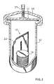
- Fig. 3 is a perspective view, partially broken away, of an anaerobic jar showing the use of the gas generating package of the invention.
- Figs. 4-7 illustrate various steps in forming one embodiment of the catalyst compartment of the invention.
- Figs. 8 and 9 illustrate steps in forming another embodiment of the catalyst compartment of the invention.
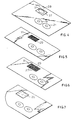
- Figs. 10-16 illustrate various steps in forming and utilizing another embodiment of the invention.
- Referring now to Fig. 1 and 2, there is shown a device for removing a pre-determined amount of oxygen from a gaseous atmosphere comprised of a package in the form of an
envelope 10. Envelope 10 is made of a suitable material which is impervious to the atmosphere and moisture, and which is inert to materials contained within the package and gases generated therein and which is not destroyed by the heat of reaction released during use of the package, as hereinafter described. Thus, for example, theenvelope 10 may be formed of a metallic foil, such as aluminum, which may be coated on its inner surface with a thermoplastic material, such as polyethylene or a polymer formed of vinyl chloride. Theenvelope 10 may be formed from two panels suitably secured together around the edges by heat sealing. In use, theenvelope 10 is placed intocontainer 32 having alid 33 which forms a gas tight seal when thebracket 34 is tightened by thescrew 35. The plated culture media in petri dishes 105 requiring a predetermined level of oxygen in the atmosphere are also placed in thecontainer 36 prior to sealing the container. The closed container has a known volume of air and hence a known volume of oxygen. The volume of the package and a given number of petri dishes is also known and is accounted for in calculating the stoichiometric amount of hydrogen generating material required to reduce the atmosphere to the predetermined level of oxygen. - The interior of the envelope is divided into a first
gas generating compartment 11 and a second liquid-receivingcompartment 12 by asuitable partition 20 which is formed, for example, by heat sealing when the top and bottom panels of the envelope are joined. Thecompartment 11 includes gas generating material in the form of atablet 13, which includes materials capable of generating hydrogen and, optionally atablet 14, which includes materials capable of generating carbon dioxide. In general, the hydrogen generating material is used in excess when an anaerobic atmosphere is desired. When sodium borohydride is used as the hydrogen generating material, about 0.9 gm is used to provide an anaerobic atmosphere in a 2.5 liter container. When sodium borohydride is used to generate a microaerophilic atmosphere in a 2.5 liter container, about 0.15 to about 0.4 gm, preferably from about 0.20 gm to about 0.35 gm is used to remove from about 20 to about 80 percent of the oxygen present. - The interior compartments 11 and 12 are in internal fluid and gas flow communication with each other through a channel in the
portion 20 at the bottom of the envelope. For purposes of discussion, the top of envelope is considered to be that end of the envelope wherein water is introduced. The bottom of the envelope is the other end. Preferably, the channel is pr-ovided with controlled transfer means, such as the use of a wick 15 (shown in phantom outline in Fig. 1 and Fig. 2). Thewick 15 is capable of permitting both liquid flow betwwen compartments 11 and 12 at a controlled rate as described in U.S. Patent No. 4,377,554, the subject matter of which is incorporated herein by reference. Thewick 15 extends through thepartition 20 into each of thecompartments wick 15 are filter paper, blotting paper, cotton twill, etc. A preferred wick material is filter paper having the designation Whatman #4. It should be understood that although the wick is shown as being a single sheet, it may be divided into two or more sheets. As particularly shown, thepartition 20 terminates before the top of the package whereby the compartments are in communication with each other throughgap 25 above the partition. The package is designed to be used in a manner such that liquid introduced intocompartment 12 does not reachgap 25 whereby only gas flow communication betweencompartments gap 25 at the top of the envelope. - In accordance with one embodiment of the present invention as shown in Figures 4-7, a
separate catalyst compartment 31 is provided withinenvelope 10. For purposes of discussion, the panel in which the catalyst compartment is formed will be referred to as the "bottom" panel. The other panel which is mated with and sealed to bottom panel to complete formation of the envelope, is referred to as the "top" panel. Fig. 4 showscompartment 31, which may be any shape, formed as a cavity in bottom panel 30 ofenvelope 10. The portion, 32,.of bottom panel 30 which forms the outside wall of thecompartment 31 is cut to provide at least onehole 28 therein, leaving aresidual flange portion 37 in the bottom of cavity. For added structural integrity a plurality of smaller holes may be used.Hole 28 provides gas communication betweencatalyst 27 and the atmosphere external toenvelope 10. As shown in Figure 5, aflash arrestor 29 is then secured to theflange 37 overhole 28 by any suitable means, such as by gluing the flash arrestor in place.Flash arrestor 29 may be of any suitable thermostable, porous material, such as fiberglass cloth, perforated metal foil or metal screening. The mesh size offlash arrestor 29 is preferably from about 100 to 300 American Standard Sieve Size, most preferably from about 180 to 220. -
Catalyst 27 is then placed incompartment 31 aboveflash arrestor 29. Althoughcatalyst 27 is particularly shown in Fig. 6 as pellets, other forms of catalyst may be used, as, for example, spheres, cylinders,, powders, strips and the like. The catalyst may be used as such, or it may be supported on an inert carrier such as alumina, carbon, fiberglass cloth, synthetic polymer and glass tape. A variety of materials may be used as the catalyst, such as platinum, rhodium, ruthenium, iridium or; preferably, palladium. -
Compartment 31 is then sealed on the internal side of the bottom panel 30 by attachment of thecover 26.Cover 26 is prepared from a su-itable material, such as metallic foil and is sealed around its edge to bottom panel 30.Cover 26 thereby protectscatalyst 27 from contact with water inwater receiving compartment 12. The water, after being added towater receiving compartment 12, is positioned adjacent to the catalyst and serves as a heat sink to remove heat fromcatalyst 27. - A second cover (not shown) is placed over
hole 28 on the outside of bottom panel 30 to protect the catalyst from ambient moisture with theenvelope 10 is used. The second cover is prepared from a suitable material, such as metallic foil and is releasably sealed around its edge to bottom panel 30. The second cover is preferably provided with a grasping portion so that the cover is easily grasped and removed by the user just before or after addition of water to water receivingcompartment 12. - A further embodiment of the invention is shown in Figures 8 and 9. In the embodiment, a unitary piece of
flame arrestor 29 is mated with abacking material 38 in a manner so as to enclose a suitable amount ofcatalyst 27 and provide acatalyst unit 39. The backing material is prepared from a suitable material, such as metal foil, and is sealed around the edge of theflame arrestor 29 to provide thecatalyst unit 39. - The
catalyst unit 39 may be placed in the cavity -formingcompartment 31 in the same manner heretofore described for the loose catalyst. Alternatively, thebacking material 38 of thecatalyst unit 39 can be adhered to the outside of the bottom panel 30for the top panel of the envelope or can be adhered to theinside wall 32 of the anaerobic jar shown in Fig. 3. - A further embodiment of the invention is drawn in Figs. 10-16. In this embodiment a
panel 36 of suitable material, such as metal foil is provided with acatalyst cavity 37 and anindicator cavity 38. The bottom of catalyst cavity is cut to provide at least one opening (not shown). Aflame arrestor 29 is secured to the flange surrounding the hole by any suitable means. Anabsorbent strip 39 capable of absorbing an indicator solution is placed in theindicator cavity 38. - As shown in Fig. 11,
catalyst pellets 27 are placed in thecatalyst cavity 39. An indicator solution is absorbed into thestrip 39. As shown in Fig. 12, acover 40 of suitable material, such as metal foil, is securely affixed over thecatalyst cavity 37. ' Apeelable cover 41 is releasably affixed over theindicator cavity 38. An adhering means 42, such as double sided adhesive tape, is provided in the space betweencover 40 and peelable cover 41. - A top view of the completed catalyst and
indicator envelope 50 is shown in Fig. 13. As shown in Fig. 14, thecover 41 is peeled away from surface surrounding theindicator cavity 38, when the envelope is placed in use. The adhering means 42 is then used to affix the envelope to the inside wall of ananaerobic jar 43 as shown in Fig. 15. This exposes the catalyst to reaction with oxygen and hydrogen through the opening in theflame arrestor 29. The hydrogen is generated by a separate hydrogen generating means (ot shown) after thejar 43 is sealed. As shown in Fig. 16, theindicator strip 39 is easily visible from outside the jar. - For the embodiment of the invention wherein it is desired to provide an atmosph'ere having a pre- determined level of carbon dixoide, a carbon dioxide generating composition if provided. The carbon dioxide generating composition includes a water soluble solid acid and a water soluble carbonate in amounts suitable for generating carbon dioxide and also for providing an acidic pH; in particular, a pH of less than 6 when dissolved in water. As representative examples of suitable acids, there may be mentioned: citric, tartatic, ascorbic, succinic, malic, fumaric, lactic acids and the like. As representative examples of suitable carbonates, there may be mentioned; sodium bicarbonate, sodium carbonate, potassium carbonate, sodium sesquicarbonate, etc. The preferred composition includes citric acid and sodium bicarbonate. The composition is preferably employed in the form of a tablet in which suitable lubricants and binders are generally also employed. It is, however, to be understood that forms other than a tablet may be used. The exact proportion of acid and carbonate will differ with the materials used. The selection of suitable amounts to provide the desired carbon dioxide concentration for culturing and the acidic pH is deemed to be within the scope of those skilled in the art from the teachings herein.
- In accordance with a particularly preferred embodiment, an oxygen indicator is also applied to the exterior of
package 10. Such an indicator may be coated or otherwise applied to the metallic foil, and such indicator, as particularly shown in Fig. 1 is in the form of three different indicators, generally indicated as 18, 19 and 21. The indicators may be of methylene blue, resazurin, and indigo carmine which respond to different levels of oxygen, or which have different oxidation-reduction potentials. The use of such indicators will indicate different levels of oxygen. A similar indicator for monitoring the level of carbon dioxide may also be applied to the external surface of the metallic foil and is generally indicated as 23. Although such indicators have been particularly shown as being printed as spots on the exterior of the package, it is to be- understood that the indicator may take other forms such as lettering or other designs. - As should be apparent, the package, in one embodiment, forms an integral unit for providing a microaerophilic or anaerobic atmosphere in that the package includes the materials for generating hydrogen and carbon dioxide, as well as the catalyst for catalyzing the reaction between hydrogen and oxygen . and the indicators for indicating oxygen concentration and carbon dioxide concentration.
- In employing the gas generating device of the present invention, the releasable cover is removed from the oustide of the
compartment 31. The liquid . receivingcompartment 12 is opened by cutting away or tearing a corner of theenvelope 10 along a tear line, generally indicated as 22. A material capable of interacting with the gas generating materials incompartment 11, such as water, is introduced intocompartment 12, and such water flows intocompartment 11, preferably at a predetermined controlled volume and rate, and preferably through thewick 15. Upon contact with water, thetablets compartment 11 intocompartment 12 through thewick 15 and/or through theopen gap 25 and ultimately into the container in which the envelope has been placed. The hydrogen reacts with oxygen in such container, with such reaction being catalyzed by thecatalyst 27 incatalyst compartment 31. In addition, oxygen levels are indicated by means of theindicators package 10. Carbon dioxide concentration is indicated byindicator 23 which is also applied to the exterior of the package. - The invention will now be further described in the following examples, however, the scope of the invention is not to be limited thereby.
- The following exemplifies a formulation to produce a microaerophilic atmosphere in accordance with the present invention, which includes a carbon dioxide generating tablet, a hydrogen generating tablet, a catalyst for the reaction between hydrogen and oxygen and oxygen indicators and carbon dioxide indicators applied to the exterior of the package. The package in accordance with the example is employed as a gas generator, with such gas generation being effected by the addition of 10 ml of water to the liquid receiving compartment.
- Citric Acid 1.850 gm Sodium Bicarbonate 0.960 gm In addition, the tablet includes suitable binder and lubricant; e.g.,0.1272 g talc and 0.531 g microcrystalline cellulose
- Sodium Borohydride .27 gm The tablet includes suitable binder and lubircants. The tablet can be coated with a water soluble gelatin to prevent decomposition.
- 1.2 g of 5% palladium on carbon catalyst
-

- Indicator Mixture 1.2 g indicator base 5 mg methylene blue Weigh 1.2 g of dry indicator mixture with 0.333 g Gum of Tragacanth. Add 40 ml of water and boil. Cool, ready for use.
- Indicator Mixture 1.2 g Indicator base 5 mg indigo carmine Weigh 1.2 g of dry indicator mixture with 0.3425 g Gum of Tragacanth. Mix with 40 ml of water and boil. Cool, ready to use.
- Indicator Mixture 1.2 g Indicator base 5 mg of resazurin Weigh 1.2 g of dry indicator mixture with 0.3345 g Gum of Tragacanth. Add 40 ml of water and boil. Cool, ready for use.
-

- Mix with 40.0 ml of water and boil. Cool, ready for use.
- In order to produce an anaerobic atmosphere in accordance with the present invention, Example 1 is repeated exactly except the hydrogen generating tablet includes 0.9 gm. of sodium borohydride.
- Two.panels of aluminum foil measuring 5.9 inches by 3.3 inches were coated on one surface each with a vinyl laminate. One of the panels has a circular cavity about 1/4 inch deep and about 1 inch in diameter in the position shown by
reference numeral 31 of Fig. 1. A single hole about 3/4 inch in diameter was punched in the bottom of the cavity. A circular piece of 200 mesh fiberglass cloth one inch in diameter was sealed in the cavity over the hole and catalyst pellets were placed on the fiberglass cloth. A 1.5 inch square of aluminum foil was placed over the cavity and heat sealed to the panel bottom portion by a heat sealing apparatus. - Hydrogen and carbon dioxide generating tablets and a rectangle of Whatman #4 filter paper measuring 3 inches by 1.2 inches were placed on the laminated surface of the bottom panel in the positions shown in Fig. 2. The two panels were mated with the laminated surfaces facing each other and were inserted into a heat sealing apparatus having mating platens in the configuration shown in shaded outline in Fig. 1. The platens were closed and the apparatus was activated to provide a pressure of 70 + 40 psig for 2-3 seconds and at a temperature of 250° - 325°F. A second cover was then releasably sealed over the hole on the exterior-side of the envelope.
- The indicators were applied to the exterior of the package as follows:
- Methylene blue - Apply 1 drop (0.05 cc.) of indicator to exterior aluminum surface of package and dry.
- Indigo carmine - Apply 1 drop.(0.05 cc.) of indicator to exterior aluminum surface of package and dry.
- Resazurin - Apply 1 drop (0.05 cc.) of indicator to exterior aluminum surface of package and dry.
- Although the invention has been described with respect to preferred embodiments thereof, it is to be understood that numerous modifications are possible within the scope of the invention. Thus, for example, a liquid other than water could be employed for generating the gas, and materials other than those particularly described could also be employed for generating gas. Thus, for example, a tablet capable of generating acetylene could be employed instead of a hydrogen generating tablet. Similarly, the tablet could be formulated for producing hydrogen in a manner other than as particularly described; e.g., hydrogen could be generated by another liquid, such as an acid; in particular, hydrochloric acid, although the use of water is preferred. Similarly, the liquid for generating the gas upon contacting the tablet could be within the package in a separate compartment or ampoule. Thus, the present invention is not limited to the particularly described embodiments, and numerous modifications and variations of the present invention are possible in light of the above teachings and, therefore, within the scope of the appended claims.
Claims (18)
Applications Claiming Priority (2)
| Application Number | Priority Date | Filing Date | Title |
|---|---|---|---|
| US584174 | 1984-02-27 | ||
| US06/584,174 US4562051A (en) | 1984-02-27 | 1984-02-27 | Generation of anaerobic or microaerophilic atmosphere |
Publications (2)
| Publication Number | Publication Date |
|---|---|
| EP0158728A1 true EP0158728A1 (en) | 1985-10-23 |
| EP0158728B1 EP0158728B1 (en) | 1987-11-04 |
Family
ID=24336201
Family Applications (1)
| Application Number | Title | Priority Date | Filing Date |
|---|---|---|---|
| EP84115555A Expired EP0158728B1 (en) | 1984-02-27 | 1984-12-15 | Generation of anaerobic or microaerophilic atmosphere |
Country Status (9)
| Country | Link |
|---|---|
| US (1) | US4562051A (en) |
| EP (1) | EP0158728B1 (en) |
| JP (1) | JPS60184382A (en) |
| AU (1) | AU561226B2 (en) |
| CA (1) | CA1235886A (en) |
| DE (1) | DE3467184D1 (en) |
| DK (1) | DK167802B1 (en) |
| FI (1) | FI79549C (en) |
| MY (1) | MY100329A (en) |
Cited By (1)
| Publication number | Priority date | Publication date | Assignee | Title |
|---|---|---|---|---|
| WO2005039291A2 (en) * | 2003-10-22 | 2005-05-06 | Fred Hutchinson Cancer Research Center | Methods, compositions and devices for inducing stasis in cells |
Families Citing this family (15)
| Publication number | Priority date | Publication date | Assignee | Title |
|---|---|---|---|---|
| US3198377A (en) * | 1962-04-30 | 1965-08-03 | Larry J Buckley | Mixing bowl with handle |
| US4976931A (en) * | 1984-02-27 | 1990-12-11 | Becton, Dickinson And Company | Generation of anaerobic or microaerophilic atmosphere |
| US4588561A (en) * | 1984-07-06 | 1986-05-13 | Becton, Dickinson And Company | Package for removing oxygen from a gaseous mixture |
| FR2582669B1 (en) * | 1985-05-30 | 1988-09-02 | Masson Alain | DEVICE BASED ON MINERAL CRYSTALLINE MATERIAL CONNECTED TO AN ENERGY SOURCE AND USE OF SAID DEVICE FOR IMPROVING BACTERIAL METABOLISM |
| US4827562A (en) * | 1987-03-20 | 1989-05-09 | Bissell Inc. | Liquid extraction surface cleaning apparatus |
| US6124804A (en) * | 1994-11-10 | 2000-09-26 | Matsushita Electric Industrial Co., Ltd. | Remote controller, remote control interface, and remote control system including a remote controller and a remote control interface |
| US6372983B1 (en) * | 1999-04-14 | 2002-04-16 | Ballard Generation Systems Inc. | Enclosure for electrical components installed in locations where a flammable gas or vapor is expected to be present |
| US6642047B2 (en) * | 2001-06-29 | 2003-11-04 | Becton, Dickinson And Company | Exothermic chemistry and method for generating an anaerobic environment |
| US20060196112A1 (en) * | 2005-03-02 | 2006-09-07 | Grant Berry | Borohydride fuel compositions and methods |
| PT1879599E (en) | 2005-04-20 | 2014-01-23 | Hutchinson Fred Cancer Res | Methods, compositions and articles of manufacture for enhancing survivability of cells, tissues, organs, and organisms |
| US20070084115A1 (en) * | 2005-10-06 | 2007-04-19 | Grant Berry | Solid fuel packaging system and method of hydrogen generation |
| US20070081939A1 (en) * | 2005-10-06 | 2007-04-12 | Grant Berry | Solid fuel packaging system and method or hydrogen generation |
| WO2009058943A1 (en) * | 2007-10-31 | 2009-05-07 | Montana State University | Gliocladium isolate c-13 and methods of its use for producing volatile compounds and hydrocarbons |
| CA2757736C (en) * | 2009-04-09 | 2017-07-18 | Colormatrix Holdings, Inc. | Scavenging oxygen |
| EP2397419B9 (en) * | 2010-06-18 | 2015-07-22 | La Seda de Barcelona S.A. | Hydrogen generating, oxygen scavenging closure cap |
Citations (5)
| Publication number | Priority date | Publication date | Assignee | Title |
|---|---|---|---|---|
| US3246959A (en) * | 1963-03-21 | 1966-04-19 | John H Brewer | Apparatus for generating gas |
| US3483089A (en) * | 1966-05-31 | 1969-12-09 | B D Lab Inc | Anaerobe jar closure assembly |
| EP0002967A2 (en) * | 1977-12-30 | 1979-07-11 | Oxoid Limited | Safety catalyst system and method of catalysing gas phase chemical reactions using the same |
| GB1567900A (en) * | 1976-10-29 | 1980-05-21 | Whiteley D | Anaerobic jars |
| EP0073590A2 (en) * | 1981-08-26 | 1983-03-09 | Becton Dickinson and Company | Article for generation of microaerophilic atmosphere |
Family Cites Families (5)
| Publication number | Priority date | Publication date | Assignee | Title |
|---|---|---|---|---|
| US3270798A (en) * | 1961-09-19 | 1966-09-06 | Universal Oil Prod Co | Catalytic radiant heat treating apparatus |
| US4013422A (en) * | 1975-12-22 | 1977-03-22 | Marion Laboratories, Inc. | Gas generating apparatus |
| US4078893A (en) * | 1976-06-30 | 1978-03-14 | The United States Of America As Represented By The Secretary Of The Army | Catalyst system for the detection and elimination of hydrogen gas |
| US4287306A (en) * | 1979-04-02 | 1981-09-01 | Becton, Dickinson And Company | Apparatus for generation of anaerobic atmosphere |
| US4347222A (en) * | 1981-04-21 | 1982-08-31 | Miles Laboratories, Inc. | Gas generating apparatus for anaerobic atmosphere |
-
1984
- 1984-02-27 US US06/584,174 patent/US4562051A/en not_active Expired - Lifetime
- 1984-11-08 CA CA000467320A patent/CA1235886A/en not_active Expired
- 1984-11-19 AU AU35657/84A patent/AU561226B2/en not_active Ceased
- 1984-12-06 JP JP59258392A patent/JPS60184382A/en active Granted
- 1984-12-12 FI FI844911A patent/FI79549C/en not_active IP Right Cessation
- 1984-12-15 DE DE8484115555T patent/DE3467184D1/en not_active Expired
- 1984-12-15 EP EP84115555A patent/EP0158728B1/en not_active Expired
-
1985
- 1985-02-22 DK DK081985A patent/DK167802B1/en not_active IP Right Cessation
-
1987
- 1987-09-29 MY MYPI87002163A patent/MY100329A/en unknown
Patent Citations (5)
| Publication number | Priority date | Publication date | Assignee | Title |
|---|---|---|---|---|
| US3246959A (en) * | 1963-03-21 | 1966-04-19 | John H Brewer | Apparatus for generating gas |
| US3483089A (en) * | 1966-05-31 | 1969-12-09 | B D Lab Inc | Anaerobe jar closure assembly |
| GB1567900A (en) * | 1976-10-29 | 1980-05-21 | Whiteley D | Anaerobic jars |
| EP0002967A2 (en) * | 1977-12-30 | 1979-07-11 | Oxoid Limited | Safety catalyst system and method of catalysing gas phase chemical reactions using the same |
| EP0073590A2 (en) * | 1981-08-26 | 1983-03-09 | Becton Dickinson and Company | Article for generation of microaerophilic atmosphere |
Cited By (3)
| Publication number | Priority date | Publication date | Assignee | Title |
|---|---|---|---|---|
| WO2005039291A2 (en) * | 2003-10-22 | 2005-05-06 | Fred Hutchinson Cancer Research Center | Methods, compositions and devices for inducing stasis in cells |
| WO2005039291A3 (en) * | 2003-10-22 | 2005-08-25 | Hutchinson Fred Cancer Res | Methods, compositions and devices for inducing stasis in cells |
| US7993681B2 (en) | 2003-10-22 | 2011-08-09 | Fred Hutchinson Cancer Research Center | Methods, compositions and devices for inducing stasis in tissues and organs |
Also Published As
| Publication number | Publication date |
|---|---|
| FI79549C (en) | 1990-01-10 |
| AU3565784A (en) | 1985-09-05 |
| FI844911L (en) | 1985-08-28 |
| DK81985D0 (en) | 1985-02-22 |
| US4562051A (en) | 1985-12-31 |
| DE3467184D1 (en) | 1987-12-10 |
| JPS6233866B2 (en) | 1987-07-23 |
| FI79549B (en) | 1989-09-29 |
| DK81985A (en) | 1985-08-28 |
| DK167802B1 (en) | 1993-12-20 |
| MY100329A (en) | 1990-08-11 |
| CA1235886A (en) | 1988-05-03 |
| EP0158728B1 (en) | 1987-11-04 |
| AU561226B2 (en) | 1987-04-30 |
| JPS60184382A (en) | 1985-09-19 |
| FI844911A0 (en) | 1984-12-12 |
Similar Documents
| Publication | Publication Date | Title |
|---|---|---|
| US4562051A (en) | Generation of anaerobic or microaerophilic atmosphere | |
| EP0017314A1 (en) | Article for formation of anaerobic atmosphere | |
| US4377554A (en) | Generation of microaerophilic atmosphere | |
| CA1247055A (en) | Generation of anaerobic or microaerophilic atmosphere | |
| US3246959A (en) | Apparatus for generating gas | |
| US4038148A (en) | Anaerobic environmental system for bacteria culture testing | |
| JP2644377B2 (en) | Oxygen-absorbent label | |
| US4013422A (en) | Gas generating apparatus | |
| US4976931A (en) | Generation of anaerobic or microaerophilic atmosphere | |
| EP2011846A1 (en) | Apparatus for heating food | |
| US4023934A (en) | Color indicator apparatus for presence of oxygen | |
| US4546086A (en) | Microbial culture apparatus | |
| US4108728A (en) | Anaerobic liquid transport apparatus | |
| US5057285A (en) | Gas generator/indicator unit adapted for use in an upright position | |
| CA1038318A (en) | Culturing means and test kit | |
| CA1129392A (en) | Safety catalyst system | |
| CA1056340A (en) | Anaerobic liquid transport apparatus | |
| CA1300056C (en) | Anaerobic gas generating system | |
| US4643973A (en) | Gas generator/indicator unit | |
| JPH0341787Y2 (en) | ||
| FI63963B (en) | FOERFARANDE FOER UTVECKLING AV GAS SAERSKILT NAER EN VISS GASATMOSFAER ERFORDRAS |
Legal Events
| Date | Code | Title | Description |
|---|---|---|---|
| PUAI | Public reference made under article 153(3) epc to a published international application that has entered the european phase |
Free format text: ORIGINAL CODE: 0009012 |
|
| AK | Designated contracting states |
Designated state(s): BE DE FR GB IT NL SE |
|
| 17P | Request for examination filed |
Effective date: 19851123 |
|
| 17Q | First examination report despatched |
Effective date: 19861021 |
|
| GRAA | (expected) grant |
Free format text: ORIGINAL CODE: 0009210 |
|
| STAA | Information on the status of an ep patent application or granted ep patent |
Free format text: STATUS: THE PATENT HAS BEEN GRANTED |
|
| AK | Designated contracting states |
Kind code of ref document: B1 Designated state(s): BE DE FR GB IT NL SE |
|
| ITF | It: translation for a ep patent filed |
Owner name: ING. C. GREGORJ S.P.A. |
|
| REF | Corresponds to: |
Ref document number: 3467184 Country of ref document: DE Date of ref document: 19871210 |
|
| ET | Fr: translation filed | ||
| PLBE | No opposition filed within time limit |
Free format text: ORIGINAL CODE: 0009261 |
|
| 26N | No opposition filed | ||
| ITTA | It: last paid annual fee | ||
| EAL | Se: european patent in force in sweden |
Ref document number: 84115555.9 |
|
| PGFP | Annual fee paid to national office [announced via postgrant information from national office to epo] |
Ref country code: DE Payment date: 20001116 Year of fee payment: 17 |
|
| PGFP | Annual fee paid to national office [announced via postgrant information from national office to epo] |
Ref country code: FR Payment date: 20001117 Year of fee payment: 17 |
|
| PGFP | Annual fee paid to national office [announced via postgrant information from national office to epo] |
Ref country code: SE Payment date: 20001120 Year of fee payment: 17 Ref country code: NL Payment date: 20001120 Year of fee payment: 17 |
|
| PGFP | Annual fee paid to national office [announced via postgrant information from national office to epo] |
Ref country code: GB Payment date: 20001121 Year of fee payment: 17 |
|
| PGFP | Annual fee paid to national office [announced via postgrant information from national office to epo] |
Ref country code: BE Payment date: 20001207 Year of fee payment: 17 |
|
| PG25 | Lapsed in a contracting state [announced via postgrant information from national office to epo] |
Ref country code: GB Free format text: LAPSE BECAUSE OF NON-PAYMENT OF DUE FEES Effective date: 20011215 |
|
| PG25 | Lapsed in a contracting state [announced via postgrant information from national office to epo] |
Ref country code: SE Free format text: LAPSE BECAUSE OF NON-PAYMENT OF DUE FEES Effective date: 20011216 |
|
| PG25 | Lapsed in a contracting state [announced via postgrant information from national office to epo] |
Ref country code: BE Free format text: LAPSE BECAUSE OF NON-PAYMENT OF DUE FEES Effective date: 20011231 |
|
| REG | Reference to a national code |
Ref country code: GB Ref legal event code: IF02 |
|
| BERE | Be: lapsed |
Owner name: BECTON DICKINSON AND CY Effective date: 20011231 |
|
| PG25 | Lapsed in a contracting state [announced via postgrant information from national office to epo] |
Ref country code: NL Free format text: LAPSE BECAUSE OF NON-PAYMENT OF DUE FEES Effective date: 20020701 |
|
| PG25 | Lapsed in a contracting state [announced via postgrant information from national office to epo] |
Ref country code: DE Free format text: LAPSE BECAUSE OF NON-PAYMENT OF DUE FEES Effective date: 20020702 |
|
| EUG | Se: european patent has lapsed |
Ref document number: 84115555.9 |
|
| GBPC | Gb: european patent ceased through non-payment of renewal fee |
Effective date: 20011215 |
|
| PG25 | Lapsed in a contracting state [announced via postgrant information from national office to epo] |
Ref country code: FR Free format text: LAPSE BECAUSE OF NON-PAYMENT OF DUE FEES Effective date: 20020830 |
|
| NLV4 | Nl: lapsed or anulled due to non-payment of the annual fee |
Effective date: 20020701 |
|
| REG | Reference to a national code |
Ref country code: FR Ref legal event code: ST |