EP0158643B1 - Electromagnetically operated hydraulic valve device with snap-together valve housing - Google Patents
Electromagnetically operated hydraulic valve device with snap-together valve housing Download PDFInfo
- Publication number
- EP0158643B1 EP0158643B1 EP84903334A EP84903334A EP0158643B1 EP 0158643 B1 EP0158643 B1 EP 0158643B1 EP 84903334 A EP84903334 A EP 84903334A EP 84903334 A EP84903334 A EP 84903334A EP 0158643 B1 EP0158643 B1 EP 0158643B1
- Authority
- EP
- European Patent Office
- Prior art keywords
- valve
- armature
- casing
- bushing
- housing
- Prior art date
- Legal status (The legal status is an assumption and is not a legal conclusion. Google has not performed a legal analysis and makes no representation as to the accuracy of the status listed.)
- Expired
Links
Images


Classifications
-
- F—MECHANICAL ENGINEERING; LIGHTING; HEATING; WEAPONS; BLASTING
- F16—ENGINEERING ELEMENTS AND UNITS; GENERAL MEASURES FOR PRODUCING AND MAINTAINING EFFECTIVE FUNCTIONING OF MACHINES OR INSTALLATIONS; THERMAL INSULATION IN GENERAL
- F16K—VALVES; TAPS; COCKS; ACTUATING-FLOATS; DEVICES FOR VENTING OR AERATING
- F16K31/00—Actuating devices; Operating means; Releasing devices
- F16K31/02—Actuating devices; Operating means; Releasing devices electric; magnetic
- F16K31/06—Actuating devices; Operating means; Releasing devices electric; magnetic using a magnet, e.g. diaphragm valves, cutting off by means of a liquid
- F16K31/0644—One-way valve
- F16K31/0655—Lift valves
- F16K31/0665—Lift valves with valve member being at least partially ball-shaped
-
- H—ELECTRICITY
- H01—ELECTRIC ELEMENTS
- H01F—MAGNETS; INDUCTANCES; TRANSFORMERS; SELECTION OF MATERIALS FOR THEIR MAGNETIC PROPERTIES
- H01F7/00—Magnets
- H01F7/06—Electromagnets; Actuators including electromagnets
- H01F7/08—Electromagnets; Actuators including electromagnets with armatures
- H01F7/16—Rectilinearly-movable armatures
- H01F7/1607—Armatures entering the winding
Definitions
- This invention relates to the use of electromagnetically operated hydraulic valve devices.
- Solenoid operated hydraulic valves have been used for many applications.
- Bouvet et al. U.S. Patent No. 4,320,781 issued March 23, 1982 and entitled “Three-Way Electrically-Actuated Hydraulic Distributor” illustrates a solenoid operated hydraulic valve device utilizing a magnetic ball displaced by energization of the electromagnetic coil.
- Komaroff et al. U.S. Patent No. 3,661,183 issued May 9, 1972 and entitled “Electromagnetically Operated Valve With Two Seats” describes a complex electromagnetically operated valve device which displaces an armature in order to move a ball valve from a valve seat.
- Eckert et al. U.S. Patent No.
- an electromagnetic valve device comprising a housing, a bushing disposed at one end thereof, a core providing end closure means for an end of said housing oppositely disposed from said bushing, said core including a longitudinal core post projecting inwardly of said housing and having an opening in said post, a bobbin having a central opening therein receiving said post, winding means supported by said bobbin and circumposing said core post, an armature movable longitudinally within said housing with one end received in the central opening of said bobbin and the other end disposed within the bushing, resilient means at least partially received by the post to act between said post and said armature, a valve casing associated with said bushing, a valve member disposed within a valve cavity in the valve casing, which casing provides opposed valve seats for the valve member, and a drive pin cooperating between said valve member and the armature, whereby said winding means is energizable to effect displacement of said armature and associated drive pin, bringing the valve
- the present invention comprises an electromagnetically operated hydraulic valve device providing an almost instantaneously responsive displacement of the valve in order to effect fluid flow relative thereto.
- the present invention is characterised in that said drive pin is free floating, and in that the valve casing comprises an outer valve casing secured over the bushing and an inner valve casing snap-fitted with the outer casing by means of an interengaging circumferential groove and circumferential boss, thereby to define the valve cavity having the opposed valve seats, in that sleeve means is disposed between the bushing and the said other end of the armature to provide a constant cross section non-magnetizable gap between said armature and said bushing, in that a residual gap is provided by a washer between said armature and said core post, and in that slot means are provided in said housing and said armature in order to preclude eddy currents and to prevent fluid lock-up.
- the sleeve means is force fitted about an end of said armature and moves therewith relative to said bushing, whilst a seal means is disposed about the exterior of said outer valve casing for providing a seal between said hydraulic valve device and an opening in a transmission apparatus.
- the resilient means preferably comprises a spring with a predetermined response rate for effecting said response.
- valve device may be operable in the reverse sense.
- the cumulative confronting areas of the bushing, sleeve and other end of said armature are substantially larger than the area between the one end of said armature and post, in order to effect a fast response time.
- the invention also relates to a method of assembling the aforesaid valve device, comprising the steps of (a) disposing the resilient means between said post and armature, (b) placing a ball valve member within valve cavity means disposed between said inner and outer valve casing, (c) fixing said inner valve casing within a cavity of said outer casing by engaging a peripheral boss about said inner valve casing with a complementary shaped groove disposed about said cavity to provide an interlocking, leak resistant securement of said inner and outer valve casings whereby said ball valve member is captured therebetween, and (d) securing said outer valve casing to said housing with a drive pin member positioned between said ball valve member and the armature whereby energization of said winding means effects substantially instantaneous displacement of said armature to effect movement of said ball valve member relative to said valve cavity means.
- the above-described electromagnetically operated hydraulic valve device is intended to provide an almost instantaneous response.
- the device in order to overcome fluid flow forces and decrease response time, the device is designed to increase the initial displacement forces effected by energization of the coils. This is accomplished by providing the constant gap in the form of the non- magnetizable sleeve disposed between the armature and the bushing.
- the ball valve can be arranged to travel only a small distance so that the required displacement of the ball valve is accomplished during the maximum force portion of solenoid operation.
- the device can also provide a residual gap between the end of the core post and the armature, the residual gap being located within the interior of the windings, thereby preventing magnetic lock-up of the armature and post.
- the longitudinal slots or openings in the cylindrical housing break up and eliminate current flow which can form in the perimeter of the housing. This results in magnetic flux flow concentrating within the desired flow path through the winding, armature, core and housing, to assist in effecting the fast response time
- the ball valve is arranged to seat tightly against the nylon valve seat of either the outervalve casing orthe inner valve casing, to provide a leak resistant valve. Additionally, the free-floating pin is designed as a separate piece rather than an integral part of the armature, in order to compensate for the stack-up of manufacturing tolerances and to eliminate alignment problems.
- the inner valve casing and outer valve casing have the afore-mentioned snap-together interfitment to preclude leakage about the valve casings and simplify assembly.
- the electromagnetically operated hydraulic valve device is referenced generally by numeral 10.
- the valve device 10 comprises a cylindrical metallic housing 12 having a plurality of longitudinal openings 14 disposed about the perimeter of housing 12. End 16 of housing 12 is open and oppositely disposed end 18 has a cylindrical bushing 19 extending therefrom. Secured over bushing 19 and housing end 18, is an outer valve casing 40 including circular seals 42 and various fluid flow openings 43, 44 and 49.
- Core member 20 encloses open end 16 of housing 12, and has a cylindrical core post 22 extending into an interior opening 32 of a nonmagnetizable, nonconductive bobbin 30.
- Nonmagnetic washer 26 is disposed over the end of core post 22.
- Coil spring 39 is received in core opening 23 and complementary opening 31 in armature 36.
- Bobbin 30 supports an electrical winding 34, the bobbin 30 being located within housing 12.
- opening 32 of bobbin 30 is one end 35 of a cylindrical metallic armature 36 having a nonmagnetizable brass sleeve 38 secured about the other end.
- Sleeve 38 can be attached either to end 33 of armature 36 or within opening 17 of bushing 19.
- Armature 36 includes a slot opening 37 which, in conjunction with housing slot opening 15, precludes eddy currents and fluid lock-up of the valve device.
- the nonmagnetizable sleeve 38 and associated end 33 of armature 36 are positioned within opening 17 of bushing 19.
- Abutting armature 36 is a free-floating metallic drive pin 50 which engages, at its other end, a glass ball valve 60.
- Glass ball valve 60 is located within the subinterior cavity 75 of inner valve casing 70, cavity 75 enclosed by valve seat 72 of inner valve casing 70 and valve seat 45 of casing 40.
- Groove 48 is disposed about the wall of outer valve casing cavity 46, and receives the circumferential boss 74 of innervalve casing 70 in orderto provide a snap-together engagement and securement of the valve casings. This provides a leak tight securement of the casings so that fluid does not leak through the casings during operation of the device.
- Ball valve 60 is made of glass and provides a leak tight engagement with the nylon material of valve casings 40 and 70. Outer valve casing 40 provides valve seat 45 and inner valve casing 70 provides valve seat 72, which when engaged by glass ball valve 60, do not allow any fluid to leak through the repective valve seat.
- Free-floating metallic drive pin 50 eliminates alignment problems between the armature 36 and the glass ball valve 60. Because pin 50 is not attached to or an integral part of armature 36, there is compensation for manufacturing tolerance variations and no problems in aligning the pin with ball valve 60.
- lnnervalve casing 70 is made of a nylon material and provides an easily assembled, snap-together fitting with outer valve casing 40.
- the snap-together fitting has proved to be leak proof and, in conjunction with the leak proof engagement of the glass ball valve 60 with valve seats 45 and 72, prevents any fluid from leaking through the hydraulic valve portion of the electromagnetic valve device. It is very importantthatfluid does not leak through the valve portion of the device because such leakage could reduce the fluid flow and pressures in the apparatus to which the valve device is attached.
- the device of the present invention effects the maximum force possible during displacement of the armature.
- the device uses only a very small operative displacement of the ball valve to accomplish the required operation of the valve.
- the nonmagnetic sleeve 38 provides a constant cross section gap between armature 36 and bushing 19. This concentrates flux flow in this area and increases the forces acting upon the armature.
- a gap A which includes the residual gap provided by washer 26, located between end 35 of armature 36 and the end of the core post 22, the gap being circumposed by winding 34.
- the inductance is affected by the flux flow at critical areas of the electromagnetic device 10. Gap A provides inductance thereacross and allows movement of the anmature towards the post.
- the arrows in the housing, winding, bushing, armature and core illustrate the flux flow path.
- the cumulative areas of the bushing, sleeve, and end 35 of armature 36 are greater than gap area A between the ends of armature 36 and post 22 in order to concentrate flux flow thereat and effect a high speed, fast response that overcomes fluid flow forces.
- openings 14 and slot 15 In order to increase the response time of the electromagnetic device, current flows through the path of least resistance, which could include circular paths within the cylindrical housing. In order to eliminate this circular flow of eddy currents, longitudinal openings 14 and slot 15 have been located within the housing 12. The openings 14 and slot 15 eliminate eddy currents and provide a route for flux flow as illustrated in FIGURE 4. However, it is important that openings 14 do not cumulatively comprise an area so large that the area of housing 12 is less than the combined area of the armature and coil. In other words, the total area of the metal housing 12 should be at least equal to or greater than the combined area of the core and armature, this relationship providing a concentration of flux lines and contributing to effecting a fast response time.
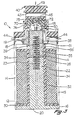
- FIGURE 3 illustrates the electromagnetic hydrau.lic valve device 10 with the ball valve 60 engaging the valve seat 45 in the closed position which prevents fluid from flowing through port 43 into sub-interior cavity 75.
- Sub-interior cavity 75 communicates through lateral passages in the inner valve casing 70 with the ports 49. Thus, fluid does flow through ports 49 into the sub-interior cavity 75, past ball valve 60, through open valve seat 72 and outwardly through ports 44.
- FIGURE 4 illustrates valve device 10 in the retracted position, after energization of the windings 34, with valve 60 engaging valve seat 72. Energization of windings 34 provides a flux flow as illustrated by the arrows, which results in a high speed displacement of armature 36 towards core post 22.
- the electromagnetically operated hydraulic valve device 10 is easily assembled and operated. Windings 34 are disposed on bobbin 30, the bobbin inserted into housing 12, and metallic core 20 threadedly inserted into open end 16 of housing 12. Inner valve casing 70 receives the glass ball valve 60 within sub-interior cavity 75, and casing 70 placed within cavity 46 and snap-fitted into engagement with casing 40. Drive pin 50 is inserted within opening 73 of inner valve casing 70, and anmature 36 and coil spring 39 inserted within bushing 19. Then outer valve casing 40 is secured over bushing 19 and to housing end 18.
- valve device Upon energization of coil winding 34, the flux flow paths illustrated in FIGURE 4 are effected and cause a high speed retraction of armature 36 towards post 20. Fluid pressure exerted upon ball valve 60 forces it out of engagement with valve seat 45 as drive pin 50 moves with armature 36, and into engagement with valve seat 72.
- Subinterior cavity 75 can be located in either the inner or outer valve casings.
- the valve device may be designed so that ball valve 60 is in a normally open position whereby retraction of anmature 36 displaces drive pin 50 against ball valve 60 to engage valve seat 45 and effect closure of the valve.
- the flow directions of the valve seats and ports are all a matter of design choice for the particular application, and such design variations of the valve device are not, per se, part of the present invention, but well within the various design modifications of the device.
- the electromagnetically operated hydraulic valve device is assembled from a minimum number of parts to provide a leak resistant hydraulic valve device with an almost instantaneous response.
- the electromagnetic valve device utilizes the maximum force available at initial energization for operation of the hydraulic valve whereby the fluid flow pressure can be easily overcome and a high speed response provided.
- the electromagnetically operated hydraulic valve device may be utilized with automotive transmissions.
Landscapes
- Engineering & Computer Science (AREA)
- Physics & Mathematics (AREA)
- Electromagnetism (AREA)
- General Engineering & Computer Science (AREA)
- Power Engineering (AREA)
- Mechanical Engineering (AREA)
- Magnetically Actuated Valves (AREA)
Abstract
Description
- This invention relates to the use of electromagnetically operated hydraulic valve devices.
- Solenoid operated hydraulic valves have been used for many applications. Bouvet et al. U.S. Patent No. 4,320,781 issued March 23, 1982 and entitled "Three-Way Electrically-Actuated Hydraulic Distributor" illustrates a solenoid operated hydraulic valve device utilizing a magnetic ball displaced by energization of the electromagnetic coil. Komaroff et al. U.S. Patent No. 3,661,183 issued May 9, 1972 and entitled "Electromagnetically Operated Valve With Two Seats" describes a complex electromagnetically operated valve device which displaces an armature in order to move a ball valve from a valve seat. Eckert et al. U.S. Patent No. 3,395,890 issued August 6, 1968 and entitled "Plastic Control Valve and Method for Making Same" describes a solenoid operated hydraulic ball valve wherein the engagement of the ball valve with a thin outer layer of unfilled plastic effects a fluid tight engagement. Giordana U.S. Patent No. 3,856,260 issued December 24, 1974 and entitled "Three-Way Solenoid Valves" illustrates a solenoid valve device which, when energized, attracts the ball valve away from the valve seat.
- From DE-A-2 124 484 is known an electromagnetic valve device comprising a housing, a bushing disposed at one end thereof, a core providing end closure means for an end of said housing oppositely disposed from said bushing, said core including a longitudinal core post projecting inwardly of said housing and having an opening in said post, a bobbin having a central opening therein receiving said post, winding means supported by said bobbin and circumposing said core post, an armature movable longitudinally within said housing with one end received in the central opening of said bobbin and the other end disposed within the bushing, resilient means at least partially received by the post to act between said post and said armature, a valve casing associated with said bushing, a valve member disposed within a valve cavity in the valve casing, which casing provides opposed valve seats for the valve member, and a drive pin cooperating between said valve member and the armature, whereby said winding means is energizable to effect displacement of said armature and associated drive pin, bringing the valve member out of engagement with one valve seat and into engagement with the other valve seat.
- These prior art patents disclose several variations of solenoid operated hydraulic valve mechanisms, which utilize generally a multiplicity of parts and interfitting mechanisms in order to provide a reliable solenoid valve.
- With the advent of electronic automotive transmissions, there has been a need for a simple, highly reliable and fast operating electromagnetic hydraulic valve device for effecting fluid flow within the transmission. The hydraulic valve device must have an almost instantaneous response, must not leak transmission fluid, comprise as few parts as possible, and provide an inexpensive, easily assembled construction.
- The present invention comprises an electromagnetically operated hydraulic valve device providing an almost instantaneously responsive displacement of the valve in order to effect fluid flow relative thereto. Starting from the valve construction known in principle from DE-A-2 124 484, the present invention is characterised in that said drive pin is free floating, and in that the valve casing comprises an outer valve casing secured over the bushing and an inner valve casing snap-fitted with the outer casing by means of an interengaging circumferential groove and circumferential boss, thereby to define the valve cavity having the opposed valve seats, in that sleeve means is disposed between the bushing and the said other end of the armature to provide a constant cross section non-magnetizable gap between said armature and said bushing, in that a residual gap is provided by a washer between said armature and said core post, and in that slot means are provided in said housing and said armature in order to preclude eddy currents and to prevent fluid lock-up.
- Preferably, the sleeve means is force fitted about an end of said armature and moves therewith relative to said bushing, whilst a seal means is disposed about the exterior of said outer valve casing for providing a seal between said hydraulic valve device and an opening in a transmission apparatus.
- The resilient means preferably comprises a spring with a predetermined response rate for effecting said response.
- Conveniently, energization of said winding effects retraction of said armature towards said post. However, the valve device may be operable in the reverse sense.
- In an embodiment, the cumulative confronting areas of the bushing, sleeve and other end of said armature are substantially larger than the area between the one end of said armature and post, in order to effect a fast response time.
- The invention also relates to a method of assembling the aforesaid valve device, comprising the steps of (a) disposing the resilient means between said post and armature, (b) placing a ball valve member within valve cavity means disposed between said inner and outer valve casing, (c) fixing said inner valve casing within a cavity of said outer casing by engaging a peripheral boss about said inner valve casing with a complementary shaped groove disposed about said cavity to provide an interlocking, leak resistant securement of said inner and outer valve casings whereby said ball valve member is captured therebetween, and (d) securing said outer valve casing to said housing with a drive pin member positioned between said ball valve member and the armature whereby energization of said winding means effects substantially instantaneous displacement of said armature to effect movement of said ball valve member relative to said valve cavity means.
- The above-described electromagnetically operated hydraulic valve device is intended to provide an almost instantaneous response. Thus, in order to overcome fluid flow forces and decrease response time, the device is designed to increase the initial displacement forces effected by energization of the coils. This is accomplished by providing the constant gap in the form of the non- magnetizable sleeve disposed between the armature and the bushing. Additionally, the ball valve can be arranged to travel only a small distance so that the required displacement of the ball valve is accomplished during the maximum force portion of solenoid operation. The device can also provide a residual gap between the end of the core post and the armature, the residual gap being located within the interior of the windings, thereby preventing magnetic lock-up of the armature and post. The longitudinal slots or openings in the cylindrical housing break up and eliminate current flow which can form in the perimeter of the housing. This results in magnetic flux flow concentrating within the desired flow path through the winding, armature, core and housing, to assist in effecting the fast response time.
- The ball valve is arranged to seat tightly against the nylon valve seat of either the outervalve casing orthe inner valve casing, to provide a leak resistant valve. Additionally, the free-floating pin is designed as a separate piece rather than an integral part of the armature, in order to compensate for the stack-up of manufacturing tolerances and to eliminate alignment problems.
- The inner valve casing and outer valve casing have the afore-mentioned snap-together interfitment to preclude leakage about the valve casings and simplify assembly.
-
- FIGURE 1 is an isometric view of the electromagnetically operated hydraulic valve device of the present invention;
- FIGURE 2 is an exploded view of the hydraulic valve device of FIGURE 1;
- FIGURE 3 is a section view along line 3-3 of FIGURE 1 and illustrating the valve device in the closed position; and
- FIGURE 4 is the section view of FIGURE 3 and illustrating the valve device in the open position.
- Referring to the drawings, particularly FIGURES 1 and 2, the electromagnetically operated hydraulic valve device is referenced generally by
numeral 10. Thevalve device 10 comprises a cylindricalmetallic housing 12 having a plurality oflongitudinal openings 14 disposed about the perimeter ofhousing 12.End 16 ofhousing 12 is open and oppositely disposedend 18 has acylindrical bushing 19 extending therefrom. Secured over bushing 19 andhousing end 18, is anouter valve casing 40 includingcircular seals 42 and variousfluid flow openings Core member 20 enclosesopen end 16 ofhousing 12, and has acylindrical core post 22 extending into aninterior opening 32 of a nonmagnetizable,nonconductive bobbin 30.Nonmagnetic washer 26 is disposed over the end ofcore post 22.Coil spring 39 is received incore opening 23 andcomplementary opening 31 inarmature 36. Bobbin 30 supports anelectrical winding 34, thebobbin 30 being located withinhousing 12. In opening 32 ofbobbin 30 is oneend 35 of a cylindricalmetallic armature 36 having anonmagnetizable brass sleeve 38 secured about the other end.Sleeve 38 can be attached either toend 33 ofarmature 36 or within opening 17 of bushing 19.Armature 36 includes aslot opening 37 which, in conjunction with housing slot opening 15, precludes eddy currents and fluid lock-up of the valve device. Thenonmagnetizable sleeve 38 and associatedend 33 ofarmature 36 are positioned within opening 17 of bushing 19. Abuttingarmature 36 is a free-floatingmetallic drive pin 50 which engages, at its other end, a glass ball valve 60. Glass ball valve 60 is located within thesubinterior cavity 75 ofinner valve casing 70,cavity 75 enclosed byvalve seat 72 ofinner valve casing 70 andvalve seat 45 ofcasing 40. Groove 48 is disposed about the wall of outervalve casing cavity 46, and receives thecircumferential boss 74 ofinnervalve casing 70 in orderto provide a snap-together engagement and securement of the valve casings. This provides a leak tight securement of the casings so that fluid does not leak through the casings during operation of the device. - Ball valve 60 is made of glass and provides a leak tight engagement with the nylon material of
valve casings Outer valve casing 40 providesvalve seat 45 andinner valve casing 70 providesvalve seat 72, which when engaged by glass ball valve 60, do not allow any fluid to leak through the repective valve seat. - Free-floating
metallic drive pin 50 eliminates alignment problems between thearmature 36 and the glass ball valve 60. Becausepin 50 is not attached to or an integral part ofarmature 36, there is compensation for manufacturing tolerance variations and no problems in aligning the pin with ball valve 60. -
lnnervalve casing 70 is made of a nylon material and provides an easily assembled, snap-together fitting withouter valve casing 40. The snap-together fitting has proved to be leak proof and, in conjunction with the leak proof engagement of the glass ball valve 60 withvalve seats - In order to provide an almost instantaneously responsive electromagnetic hydraulic valve device, the device of the present invention effects the maximum force possible during displacement of the armature. In order to utilize the maximum force that occurs during operation of the solenoid, the device uses only a very small operative displacement of the ball valve to accomplish the required operation of the valve.
- Referring to FIGURE 3 which is a section view of the hydraulic valve device, the
nonmagnetic sleeve 38 provides a constant cross section gap betweenarmature 36 and bushing 19. This concentrates flux flow in this area and increases the forces acting upon the armature. There is a gap A, which includes the residual gap provided bywasher 26, located betweenend 35 ofarmature 36 and the end of thecore post 22, the gap being circumposed by winding 34. The inductance is affected by the flux flow at critical areas of theelectromagnetic device 10. Gap A provides inductance thereacross and allows movement of the anmature towards the post. The arrows in the housing, winding, bushing, armature and core (FIGURE 4) illustrate the flux flow path. The cumulative areas of the bushing, sleeve, and end 35 ofarmature 36 are greater than gap area A between the ends ofarmature 36 and post 22 in order to concentrate flux flow thereat and effect a high speed, fast response that overcomes fluid flow forces. - In order to increase the response time of the electromagnetic device, current flows through the path of least resistance, which could include circular paths within the cylindrical housing. In order to eliminate this circular flow of eddy currents,
longitudinal openings 14 andslot 15 have been located within thehousing 12. Theopenings 14 andslot 15 eliminate eddy currents and provide a route for flux flow as illustrated in FIGURE 4. However, it is important thatopenings 14 do not cumulatively comprise an area so large that the area ofhousing 12 is less than the combined area of the armature and coil. In other words, the total area of themetal housing 12 should be at least equal to or greater than the combined area of the core and armature, this relationship providing a concentration of flux lines and contributing to effecting a fast response time. - FIGURE 3 illustrates the electromagnetic hydrau.lic
valve device 10 with the ball valve 60 engaging thevalve seat 45 in the closed position which prevents fluid from flowing throughport 43 intosub-interior cavity 75.Sub-interior cavity 75 communicates through lateral passages in theinner valve casing 70 with theports 49. Thus, fluid does flow throughports 49 into thesub-interior cavity 75, past ball valve 60, throughopen valve seat 72 and outwardly throughports 44. FIGURE 4 illustratesvalve device 10 in the retracted position, after energization of thewindings 34, with valve 60 engagingvalve seat 72. Energization ofwindings 34 provides a flux flow as illustrated by the arrows, which results in a high speed displacement ofarmature 36 towardscore post 22. This high speed response permits a correspondingly quick retraction ofdrive pin 50 which allows ball valve 60 to unseat fromvalve seat 45 and engagevalve seat 72. Communication between thesub-interior cavity 75 and theports 44 is thereby closed, but fluid can flow throughport 43, into thesub-interior cavity 75 viaopen valve seat 45, and then outwardly throughports 49. - The electromagnetically operated
hydraulic valve device 10 is easily assembled and operated.Windings 34 are disposed onbobbin 30, the bobbin inserted intohousing 12, andmetallic core 20 threadedly inserted intoopen end 16 ofhousing 12.Inner valve casing 70 receives the glass ball valve 60 withinsub-interior cavity 75, and casing 70 placed withincavity 46 and snap-fitted into engagement withcasing 40. Drivepin 50 is inserted within opening 73 ofinner valve casing 70, and anmature 36 andcoil spring 39 inserted withinbushing 19. Thenouter valve casing 40 is secured overbushing 19 and tohousing end 18. - Upon energization of coil winding 34, the flux flow paths illustrated in FIGURE 4 are effected and cause a high speed retraction of
armature 36 towardspost 20. Fluid pressure exerted upon ball valve 60 forces it out of engagement withvalve seat 45 asdrive pin 50 moves witharmature 36, and into engagement withvalve seat 72. It should be clearly understood that the design of the hydraulic valve portion of the device is a matter of design choice.Subinterior cavity 75 can be located in either the inner or outer valve casings. The valve device may be designed so that ball valve 60 is in a normally open position whereby retraction ofanmature 36 displaces drivepin 50 against ball valve 60 to engagevalve seat 45 and effect closure of the valve. The flow directions of the valve seats and ports are all a matter of design choice for the particular application, and such design variations of the valve device are not, per se, part of the present invention, but well within the various design modifications of the device. - The electromagnetically operated hydraulic valve device is assembled from a minimum number of parts to provide a leak resistant hydraulic valve device with an almost instantaneous response. The electromagnetic valve device utilizes the maximum force available at initial energization for operation of the hydraulic valve whereby the fluid flow pressure can be easily overcome and a high speed response provided.
- The electromagnetically operated hydraulic valve device may be utilized with automotive transmissions.
Claims (7)
Applications Claiming Priority (2)
| Application Number | Priority Date | Filing Date | Title |
|---|---|---|---|
| US537532 | 1983-09-30 | ||
| US06/537,532 US4509716A (en) | 1983-09-30 | 1983-09-30 | Electromagnetically operated hydraulic valve device with snap-together valve housing |
Publications (3)
| Publication Number | Publication Date |
|---|---|
| EP0158643A1 EP0158643A1 (en) | 1985-10-23 |
| EP0158643A4 EP0158643A4 (en) | 1986-02-13 |
| EP0158643B1 true EP0158643B1 (en) | 1989-05-24 |
Family
ID=24143042
Family Applications (1)
| Application Number | Title | Priority Date | Filing Date |
|---|---|---|---|
| EP84903334A Expired EP0158643B1 (en) | 1983-09-30 | 1984-09-05 | Electromagnetically operated hydraulic valve device with snap-together valve housing |
Country Status (5)
| Country | Link |
|---|---|
| US (1) | US4509716A (en) |
| EP (1) | EP0158643B1 (en) |
| JP (1) | JPS61500030A (en) |
| DE (1) | DE3478337D1 (en) |
| WO (1) | WO1985001561A1 (en) |
Families Citing this family (27)
| Publication number | Priority date | Publication date | Assignee | Title |
|---|---|---|---|---|
| DE3724218A1 (en) * | 1987-07-22 | 1989-02-02 | Pierburg Gmbh | ELECTROMAGNETIC CONTROL VALVE |
| US4826130A (en) * | 1987-11-18 | 1989-05-02 | Itt Corporation | High-speed solenoid valve with polymer film lubricant |
| DE3908859A1 (en) * | 1989-03-17 | 1990-09-20 | Rexroth Mannesmann Gmbh | Ball switching valve, in particular for chopper operation |
| US5174262A (en) * | 1989-04-14 | 1992-12-29 | Brunswick Corporation | Control valve for fuel injection |
| JPH03157576A (en) * | 1989-11-15 | 1991-07-05 | Aisin Aw Co Ltd | Three-way solenoid valve and manufacture thereof |
| JPH03199788A (en) * | 1989-12-28 | 1991-08-30 | Aisin Aw Co Ltd | Two-way electromagnetic valve |
| JPH03199789A (en) * | 1989-12-28 | 1991-08-30 | Aisin Aw Co Ltd | Electromagnetic valve |
| IT220662Z2 (en) * | 1990-10-31 | 1993-10-08 | Elasis Sistema Ricerca Fita Nel Mezzogiorno Soc.Consortile P.A. | IMPROVEMENTS TO THE PILOT VALVE AND TO THE RELATED STILL OF ORDER AN ELECTROMAGNETIC INJECTOR FOR FUEL INJECTION SYSTEMS OF INTERNAL COMBUSTION ENGINES |
| US5145148A (en) * | 1991-11-14 | 1992-09-08 | Siemens Automotive L.P. | Solenoid valve operating mechanism comprising a pin having a plastic sleeve molded onto a metal core |
| IT1258956B (en) * | 1992-06-08 | 1996-03-11 | MINIATURIZED SOLENOID VALVE DEVICE AND PROCEDURE FOR ITS PREPARATION | |
| US5299600A (en) * | 1992-09-14 | 1994-04-05 | Sterling Hydraulics, Inc. | Analog proportional pressure control three-way valve |
| DE4328043A1 (en) * | 1993-08-20 | 1995-02-23 | Hydac Filtertechnik Gmbh | Venting device with actuation magnet |
| DE9317864U1 (en) * | 1993-11-23 | 1994-02-10 | KENDRION Binder Magnete GmbH, 78048 Villingen-Schwenningen | magnetic valve |
| US5606992A (en) * | 1994-05-18 | 1997-03-04 | Coltec Industries Inc. | Pulse width modulated solenoid |
| AU2167197A (en) * | 1996-03-22 | 1997-10-17 | Smith International, Inc. | Actuating ball |
| JP3471568B2 (en) * | 1997-06-18 | 2003-12-02 | 三菱電機株式会社 | Three-way solenoid valve |
| US6142394A (en) * | 1999-06-30 | 2000-11-07 | Caterpillar Inc. | Valve seat for a ball and pin valve member in a hydraulically actuated fuel injector |
| JP4058749B2 (en) * | 2000-02-16 | 2008-03-12 | 株式会社デンソー | Electromagnetic drive device and electromagnetic valve using the same |
| ITBO20010145A1 (en) * | 2001-03-16 | 2002-09-16 | Magneti Marelli Spa | ELECTRICALLY OPERATED THREE-WAY VALVE |
| US7100889B2 (en) * | 2003-12-18 | 2006-09-05 | Delaware Capital Formation, Inc. | Miniature electrically operated solenoid valve |
| US7866301B2 (en) * | 2009-01-26 | 2011-01-11 | Caterpillar Inc. | Self-guided armature in single pole solenoid actuator assembly and fuel injector using same |
| DE102009029565A1 (en) * | 2009-09-18 | 2011-03-31 | Robert Bosch Gmbh | Magnetic assembly for a solenoid valve and corresponding solenoid valve |
| CN102326016B (en) * | 2009-12-21 | 2013-08-28 | 丰田自动车株式会社 | Electromagnetic linear valve |
| CN104011443B (en) * | 2011-10-14 | 2017-12-15 | 弗路德自动控制系统有限公司 | Solenoid valve with metal tube bobbin |
| DE102012001100A1 (en) * | 2012-01-23 | 2013-07-25 | Wabco Gmbh | Arrangement for controlling a double-acting switching cylinder of a Schaltanord-tion of an automated transmission of a motor vehicle |
| KR102008824B1 (en) | 2012-06-21 | 2019-08-08 | 보르그워너 인코퍼레이티드 | Immersible solenoid valve |
| US20140246615A1 (en) * | 2013-03-04 | 2014-09-04 | Emerson Electric Co. | Systems and Apparatuses for a Simplified Solenoid Valve Assembly |
Citations (3)
| Publication number | Priority date | Publication date | Assignee | Title |
|---|---|---|---|---|
| US3395890A (en) * | 1965-10-23 | 1968-08-06 | Chandler Evans Inc | Plastic control valve and method for making same |
| US3856260A (en) * | 1972-03-31 | 1974-12-24 | Peugeot & Renault | Three-way solenoid valves |
| US4320781A (en) * | 1978-10-16 | 1982-03-23 | Regie Nationale Des Usines Renault | Three-way electrically-actuated hydraulic distributor |
Family Cites Families (14)
| Publication number | Priority date | Publication date | Assignee | Title |
|---|---|---|---|---|
| US1650799A (en) * | 1924-05-17 | 1927-11-29 | North East Electric Co | Electric solenoid |
| US2121657A (en) * | 1936-02-01 | 1938-06-21 | James B Fisher | Electromagnetic control means |
| US2151213A (en) * | 1937-12-03 | 1939-03-21 | Remington Rand Inc | Solenoid |
| US2449438A (en) * | 1944-07-25 | 1948-09-14 | Adel Prec Products Corp | Solenoid with plunger |
| US2415739A (en) * | 1944-09-21 | 1947-02-11 | Bendix Aviat Corp | Solenoid |
| US3451429A (en) * | 1966-09-28 | 1969-06-24 | Bendix Corp | Control valve providing means for minimizing seat wear |
| DE1934212A1 (en) * | 1969-07-05 | 1971-01-14 | Bosch Gmbh Robert | Impulse controlled double seat solenoid valve |
| DE2046153A1 (en) * | 1970-09-18 | 1972-03-30 | Teves Gmbh Alfred | Electromagnetically operated valve |
| DE2124484A1 (en) * | 1971-05-18 | 1972-11-30 | Zahnradfabrik Friedrichshafen | Electromagnetically operated valve |
| DE2337843C2 (en) * | 1973-07-25 | 1982-10-28 | Robert Bosch Gmbh, 7000 Stuttgart | Solenoid for solenoid operated valves |
| US3921111A (en) * | 1974-09-25 | 1975-11-18 | Marotta Scientific Controls | Solenoid actuator for high pressure valve |
| US4067541A (en) * | 1976-03-26 | 1978-01-10 | The Toro Company | Water valve operating solenoid |
| DE7809106U1 (en) * | 1978-03-25 | 1979-08-30 | Robert Bosch Gmbh, 7000 Stuttgart | ELECTROMAGNETIC CONTROL DEVICE, IN PARTICULAR FOR FUEL INJECTION SYSTEMS |
| DE3147058C2 (en) * | 1981-11-27 | 1990-10-04 | bso Steuerungstechnik GmbH, 6603 Sulzbach | Actuating magnet, especially direct current lifting magnet |
-
1983
- 1983-09-30 US US06/537,532 patent/US4509716A/en not_active Expired - Fee Related
-
1984
- 1984-09-05 JP JP59503302A patent/JPS61500030A/en active Pending
- 1984-09-05 DE DE8484903334T patent/DE3478337D1/en not_active Expired
- 1984-09-05 EP EP84903334A patent/EP0158643B1/en not_active Expired
- 1984-09-05 WO PCT/US1984/001396 patent/WO1985001561A1/en not_active Ceased
Patent Citations (3)
| Publication number | Priority date | Publication date | Assignee | Title |
|---|---|---|---|---|
| US3395890A (en) * | 1965-10-23 | 1968-08-06 | Chandler Evans Inc | Plastic control valve and method for making same |
| US3856260A (en) * | 1972-03-31 | 1974-12-24 | Peugeot & Renault | Three-way solenoid valves |
| US4320781A (en) * | 1978-10-16 | 1982-03-23 | Regie Nationale Des Usines Renault | Three-way electrically-actuated hydraulic distributor |
Also Published As
| Publication number | Publication date |
|---|---|
| DE3478337D1 (en) | 1989-06-29 |
| EP0158643A1 (en) | 1985-10-23 |
| JPS61500030A (en) | 1986-01-09 |
| US4509716A (en) | 1985-04-09 |
| EP0158643A4 (en) | 1986-02-13 |
| WO1985001561A1 (en) | 1985-04-11 |
Similar Documents
| Publication | Publication Date | Title |
|---|---|---|
| US4509716A (en) | Electromagnetically operated hydraulic valve device with snap-together valve housing | |
| EP2916056B1 (en) | Solenoid operated fluid control valve | |
| US5402093A (en) | Electromagnet having an armature with an injection-molded guide or control rod | |
| CA2269302C (en) | Proportional variable force solenoid control valve with segmented permanent magnet | |
| US4559971A (en) | Single coil vacuum/vent valve | |
| US5474107A (en) | Fail-open solenoid actuated valve | |
| US3788597A (en) | Electromagnetic flow controlling valve | |
| EP0222223B1 (en) | Inline solenoid operated slide valve | |
| JPH0559307B2 (en) | ||
| US5413308A (en) | Fail-open solenoid actuated valve | |
| EP3259510B1 (en) | Solenoid apparatus | |
| US20040195537A1 (en) | Pneumatic module | |
| US5174336A (en) | General purpose fluid control valve | |
| EP1790889A1 (en) | Valve gear | |
| US4694270A (en) | Electromagnetic proportional actuator | |
| EP1008791B1 (en) | Solenoid valve | |
| GB2061015A (en) | Direct current solenoid operator | |
| US4677409A (en) | Electromagnetic solenoid with a replaceable fixed iron core | |
| WO2021009776A1 (en) | Solenoid operated three way hydraulic valve | |
| CA1207732A (en) | Electromagnetically operated hydraulic valve device with snap-together valve housing | |
| EP0094610A2 (en) | Solenoid operated valve for oil hydraulic circuit and method for assembling same | |
| RU1808063C (en) | Electromagnetic valve | |
| JPH0557562U (en) | Valve device | |
| JPH0893948A (en) | Solenoid valve device |
Legal Events
| Date | Code | Title | Description |
|---|---|---|---|
| PUAI | Public reference made under article 153(3) epc to a published international application that has entered the european phase |
Free format text: ORIGINAL CODE: 0009012 |
|
| 17P | Request for examination filed |
Effective date: 19850515 |
|
| AK | Designated contracting states |
Designated state(s): DE GB |
|
| RIN1 | Information on inventor provided before grant (corrected) |
Inventor name: LLOYD, CHARLES, F. Inventor name: BARBER, MICHAEL |
|
| A4 | Supplementary search report drawn up and despatched |
Effective date: 19860213 |
|
| 17Q | First examination report despatched |
Effective date: 19870713 |
|
| GRAA | (expected) grant |
Free format text: ORIGINAL CODE: 0009210 |
|
| AK | Designated contracting states |
Kind code of ref document: B1 Designated state(s): DE GB |
|
| REF | Corresponds to: |
Ref document number: 3478337 Country of ref document: DE Date of ref document: 19890629 |
|
| PLBE | No opposition filed within time limit |
Free format text: ORIGINAL CODE: 0009261 |
|
| STAA | Information on the status of an ep patent application or granted ep patent |
Free format text: STATUS: NO OPPOSITION FILED WITHIN TIME LIMIT |
|
| 26N | No opposition filed | ||
| PGFP | Annual fee paid to national office [announced via postgrant information from national office to epo] |
Ref country code: DE Payment date: 19910822 Year of fee payment: 8 |
|
| PGFP | Annual fee paid to national office [announced via postgrant information from national office to epo] |
Ref country code: GB Payment date: 19910829 Year of fee payment: 8 |
|
| PG25 | Lapsed in a contracting state [announced via postgrant information from national office to epo] |
Ref country code: GB Effective date: 19920905 |
|
| GBPC | Gb: european patent ceased through non-payment of renewal fee |
Effective date: 19920905 |
|
| PG25 | Lapsed in a contracting state [announced via postgrant information from national office to epo] |
Ref country code: DE Effective date: 19930602 |