EP0157542A2 - Electrical connectors - Google Patents
Electrical connectors Download PDFInfo
- Publication number
- EP0157542A2 EP0157542A2 EP85301942A EP85301942A EP0157542A2 EP 0157542 A2 EP0157542 A2 EP 0157542A2 EP 85301942 A EP85301942 A EP 85301942A EP 85301942 A EP85301942 A EP 85301942A EP 0157542 A2 EP0157542 A2 EP 0157542A2
- Authority
- EP
- European Patent Office
- Prior art keywords
- coupling sleeve
- electrical connector
- sleeve
- movable parts
- retaining sleeve
- Prior art date
- Legal status (The legal status is an assumption and is not a legal conclusion. Google has not performed a legal analysis and makes no representation as to the accuracy of the status listed.)
- Withdrawn
Links
Images



Classifications
-
- H—ELECTRICITY
- H01—ELECTRIC ELEMENTS
- H01R—ELECTRICALLY-CONDUCTIVE CONNECTIONS; STRUCTURAL ASSOCIATIONS OF A PLURALITY OF MUTUALLY-INSULATED ELECTRICAL CONNECTING ELEMENTS; COUPLING DEVICES; CURRENT COLLECTORS
- H01R13/00—Details of coupling devices of the kinds covered by groups H01R12/70 or H01R24/00 - H01R33/00
- H01R13/62—Means for facilitating engagement or disengagement of coupling parts or for holding them in engagement
- H01R13/622—Screw-ring or screw-casing
-
- H—ELECTRICITY
- H01—ELECTRIC ELEMENTS
- H01R—ELECTRICALLY-CONDUCTIVE CONNECTIONS; STRUCTURAL ASSOCIATIONS OF A PLURALITY OF MUTUALLY-INSULATED ELECTRICAL CONNECTING ELEMENTS; COUPLING DEVICES; CURRENT COLLECTORS
- H01R13/00—Details of coupling devices of the kinds covered by groups H01R12/70 or H01R24/00 - H01R33/00
- H01R13/62—Means for facilitating engagement or disengagement of coupling parts or for holding them in engagement
- H01R13/629—Additional means for facilitating engagement or disengagement of coupling parts, e.g. aligning or guiding means, levers, gas pressure electrical locking indicators, manufacturing tolerances
- H01R13/633—Additional means for facilitating engagement or disengagement of coupling parts, e.g. aligning or guiding means, levers, gas pressure electrical locking indicators, manufacturing tolerances for disengagement only
- H01R13/635—Additional means for facilitating engagement or disengagement of coupling parts, e.g. aligning or guiding means, levers, gas pressure electrical locking indicators, manufacturing tolerances for disengagement only by mechanical pressure, e.g. spring force
Definitions
- This invention relates to electrical connectors, and in particular it relates to electrical connectors having means for reducing the possibility of the connector becoming disengaged due to vibration.
- a previously proposed electrical connector comprises a plug, a socket, and a coupling sleeve mounted on the plug so that it can rotate about the longitudinal axis of the plug.
- the coupling sleeve is arranged so that it can be screwed onto the socket thereby drawing the plug and socket together.
- the coupling sleeve can secure the plug and socket together by way of a bayonet action.
- an electrical connector comprising a socket part and a plug part, wherein one of the parts has a coupling sleeve rotatable thereon in one direction for coupling the socket part and the plug part together, characterised in that a thrust washer is disposed between the coupling sleeve and said one part, the thrust washer being provided with a ratchet-like means operative to permit rotation of the coupling sleeve in the said one direction with a lower torque than that required to effect rotation in the opposite direction thereby to resist decoupling of the plug and socket parts by rotation.
- the thrust washer preferably comprises an annular washer part
- the ratchet means may comprise a plurality of circumferentially disposed arms, one end of each arm being attached to the annular washer part and the end of each arm remote from the attached end being provided with a detent for engaging toothed formations on said one part.
- the ratchet-like means enables the coupling sleeve to be rotated to allow connection of the plug and socket, but the coupling sleeve resists rotation in the opposite direction so that if the electrical connector is subjected to vibration, the thrust washer eliminates or at least reduces the possibility of the coupling sleeve rotating and causing the connector to become disengaged.
- One of the parts may have a screw thread means on its outer surface and the coupling sleeve may have an internal screw thread means which is complementary with the screw thread means of said one part.
- One of the screw thread means may be defined by a plurality of radially movable parts which are disposed circumferentially within the connector to engage the other of the screw thread means.
- the radially movable parts are slidably located in circumferentially disposed apertures
- the connector includes a retaining sleeve which is movable relative to the movable parts, so that when it is moved into one position, it restrains the movable parts from sliding so that they engage the other screw thread means when the plug part and the socket part are connected, and when moved into another position allows the movable parts to slide away from the other screw thread means, thereby enabling disconnection of the plug part and the socket part.
- the movable parts may be operatively associated with the coupling sleeve and captive therein.
- the movable parts may be arranged to lie equiangularly about the longitudinal axis of the connector so that they define the internal screw thread means of the other part and engage roots of adjacent threads of the other thread means.
- the movable parts themselves may be in the form of elongate members which extend radially within the connector and may be rounded at either or both ends and each may be provided with a flange which engages with a seat on the coupling sleeve which limits the distance of travel of the sliding part in a radial direction.
- the movable parts may alternatively be in the form of arcuate segments lying equiangularly about the longitudinal axis of the connector.
- each of the arcuate segments is preferably provided with one or more projections on its inwardly curved surface, which projections are preferably in the form of part of a helical thread.
- the helical threads of the movable parts together make up the internal screw thread means.
- the outwardly curved surface of the movable parts is also provided with one or more projections or ribs which butt against the retaining sleeve when in said one position.
- the coupling sleeve has circumferentially extending apertures which have at least one pair of opposite sloping sides.
- the arcuate segments have corresponding sloping sides which co-operate with the sloping sides of the coupling sleeve to limit inward radial movement of the segments within the connector.
- the retaining sleeve may be of an annular cross section and may be provided with one or more recesses or holes suitable for receiving one end of the movable parts, or for receiving the one or more projections or ribs of th F arcuate segments, so that when the retaining sleeve is moved into the said another position, the movable parts cai move radially outwardly to permit disconnection of the connector.
- the retaining sleeve may be provided with a helical recess for receiving the elongate movable parts, which helical recess corresponds to the helical arrangement of the elongate movable parts.
- the retaining sleeve may be urged to rest at the one position by means of a spring.
- the spring may be positioned between the coupling sleeve and the retaining sleeve.
- the coupling sleeve may include a flange which, when the two parts are disconnected, is sandwiched between a stop and a spring washer on said other part, whereby the spring washer urges said other part towards said one part when the two parts are connected together.
- the connector may be provided with an indexing means.
- the indexing means may be in the form of a guide for example, which projects at a point on the periphery of the one part, which guide corresponds with a recess in the periphery of the other part.
- the retaining sleeve may be attached to a lanyard thereby enabling the one part and the other part to be remotely separated, by pulling the lanyard, whereby the retaining sleeve slides into said another position, thereby enabling the movable parts to slide into the holes or recesses or helical recess provided in the retaining sleeve.
- the one part corresponds to the socket part and the other part corresponds to the plug part.
- Embodiments of the present invention provide connectors which are compact and which facilitate rapid an ⁇ reliable decoupling of screw coupled parts. Further, the simple construction of such connectors increases their reliability during use under adverse conditions such as icing.
- a connector in which a socket part 2 and a plug part 4 are coupled together.
- the socket part 2 is of circular cross-section and has a screw thread means, in this case a helical screw thread 6, formed on its outer periphery at one end.
- the socket part 2 houses a moulded block 8 of insulating material, which block 8 provides support for a number of conductive socket elements 10.
- the plug part 4 comprises an inner shell 12 which is positioned within the socket part 2 and which houses a moulded block 14 of insulating material.
- the block 14 supports electrical connector pins 16 corresponding to the conductive socket elements 10 of the socket part 2.
- the electrical pins 16 are received by the conductive socket elements 10 thereby effecting electrical connection between the socket part 2 and the plug part 4.
- a rubber sealing gasket 18 is provided on the inner surface of the socket part 2 to provide a seal between the socket part 2 and the plug part 4 when they are coupled together.
- a coupling sleeve 20 is captive on the outer surface of the plug part 4 and has an internal screw thread means 22 which is defined by a plurality of elongate movable or sliding parts 24 having hemispherical ends.
- the sliding parts 24 are slidably located in radially extending apertures formed in the coupling sleeve 20 and they define a helical path which corresponds to the helical screw thread 6.
- the radially inward ends of the sliding parts 24 engage roots of the helical screw thread 6 when the socket part 2 and the plug part 4 are connected.
- the radially outward ends of the sliding parts 24 butt against a retaining sleeve 26 which is slidably mounted on the coupling sleeve 20.
- a thrust washer 30 (to be described in detail later with reference to Figures 8a, 8b and 9) is sandwiched between a stop 32 formed on the outer periphery of the inner shell 12, and a flange 34, which flange forms part of the coupling sleeve 20.
- the thrust washer 30 urges the socket part 2 towards the plug part 4 when the two parts are coupled together.
- This arrangement enables the coupling sleeve 20 to be captive on the plug part 4 so that it is free to rotate about the longitudinal axis of the connector. It will be appreciated that the foregoing arrangement is such that the coupling sleeve 20 can be screwed on to or off the socket part 2 by rotating the coupling sleeve about the longitudinal axis of the connector in the appropriate direction.
- the thrust washer 30 is operative to permit rotation of the coupling sleeve 20 in the screw on direction with relative ease while being operative, by way of a ratchet-like means (to be described later), to resist rotation in the unscrew direction.
- a lanyard 36 is attached to the retaining sleeve 26 in the manner shown.
- the retaining sleeve 26 slides, relati ⁇ e to the coupling sleeve 20 and the sliding parts 24, in the direction of arrow A against the action of the spring 28.
- the distance of travel of the retaining sleeve 26 is limited by means of a retaining pin 38 which passes through an elongate hole 39 in the retaining sleeve 26, which hole 39 defines the distance through which the retaining sleeve 26 may be moved.
- the retaining sleeve 26 has been moved in the direction of arrow A so that one end of the hole 39 butts up against the pin 38, and a helical recess 40, formed in the retaining sleeve 26 (shown in Figure 1 as a pair of semi-circular recesses), is located adjacent to the sliding parts 24.
- the sliding parts 24 are then free to slide radially outwardly when made to do so by shearing forces (due to the exertion of the force on the lanyard 36) between the hemispherical ends of the sliding parts 24 and the side of the helical screw thread 6.
- the socket part 2 and the plug part 4 are shown to be disconnected, but a force is still being exerted on the lanyard 36 so that the retaining sleeve 26 remains in the appropriate position for disengagement of the socket part 2 and the plug part 4.
- the thrust washer 30 expands and so causes the flange 34 of the coupling sleeve 20 to butt up against a retaining ring 42 located on the outer periphery of the inner shell 12, thereby preventing the coupling sleeve 20 from becoming detached from the inner shell 12.
- the sliding parts 24 are each provided with a flange 44 which can engage with a seat 46 located in respective radially extending apertures.
- the connector is provided with an indexing means so that the electrical pin 16 of the plug part 4 can be aligned with correct socket elements 10 of the socket part 2 when the two parts are to be connected.
- the indexing means comprises a guide 48 which projects from the periphery of the plug part 4, and a recess 50 situated on the periphery of the socket part 2, which recess 50 receives the guide when the two parts are coupled together.
- the electrical connector comprises a socket part 52 and a plug part 54 shown connected together.
- the socket part 52 has an external screw thread 56 on its outer periphery.
- a coupling sleeve 62 is captive on the outer surface of the plug part 54 and has an internal screw thread means which is defined by six arcuate movable parts 58 having projections 59 on their inwardly curved surface.
- the projections 59 which although shown as having a hemispherical cross section may alternatively be trapezoidal in cross section, form part of a helical thread.
- the projections 59 of the six movable parts 58 together make up a double thread having a triple thread start.
- the movable parts 58 also have projections 60 on their outwardly curved surface.
- the projections 60 are in the form of a pair of annular ribs which butt against a retaining sleeve 61 when the socket part 52 and the plug part 54 are connected together.
- Each of the arcuate segments 58 is disposed in a circunferentially extending aperture in the coupling sleeve 62.
- the retaining sleeve 61 is mounted on the outer surface of the coupling sleeve 62 and is slidable relative thereto in a direction parallel to the longitudinal axis of the connector and is rotatable about the longitudinal axis of the connector.
- the retaining sleeve 61 has a pair of recesses 63 which correspond to the projections 60 of the arcuate segments 58.
- the retaining sleeve 61 is located in a radial direction by means of an end cap 65 which is screwed and locked to the coupling sleeve 62 by means of a screw thread 65a.
- the outer circumferential surface of the end cap 65 is knurled thereby facilitating an improved hand gripping surface.
- a spring 68 (to be described in further detail later) is disposed between the retaining sleeve 61 and the coupling sleeve 62.
- the spring 68 urges the retaining sleeve 61 towards the position shown in Figure 4 so that in the absence of a force in the direction of the arrow A, the retaining sleeve 61 restrains the arcuate segments 58 from moving radially outwardly and hence the electrical connector remains connected.
- a thrust washer 66 (to be further described later) is located between the coupling sleeve 62 and the plug part 54.
- the thrust washer is provided with a ratchet-like means operative to permit rotation of the coupling sleeve 62 in one direction with a lower torque than that required to effect rotation of the coupling sleeve in the opposite direction.
- a circlip 67 is located into a recess formed in the coupling sleeve 62, which circlip serves to secure the thrust washer 66, and the coupling sleeve 62 in position.
- a lanyard attachment ring 90 is positioned within a radially inner surface of the retaining sleeve 61 as shown in Figure 4.
- a lanyard 70 is fixed to the lanyard attachment ring 90.
- An end portion 69 of the retaining sleeve 61 is spun over so as to captivate the lanyard attachment ring 90 whilst allowing the retaining sleeve 61 to rotate relative to the ring 90. This ensures that the lanyard 70 always remains in the same attitude relative to the plug part 54.
- FIG. 5 an end view of the coupling sleeve 62 is shown taken from the direction of an arrow B of Figure 4.
- the coupling sleeve 62 has an inwardly directed flange 71 which has four slots 72 disposed along its circumference, which slots allow the thrust washer 66 and the circlip 67 to be put into position.
- the coupling sleeve 62 has six circumferentially extending apertures 73 which correspond in size to the arcuate segments 58.
- Each of the apertures 73 has a pair of opposite sloping sides 74 which cooperate with a pair of sloping sides 74a of the arcuate segment 58 so as to limit inward radial movement of the segment 58 when disposed within the apertures 73 of the coupling sleeve 62.
- Figure 7a shows a plan view and Figure 7b shows a side elevational view of the spring 68.
- the spring 68 may be formed from, for example, piano wire and may consist of five lobes, each lobe having a pair of sloping surfaces 75a and 75b of different lengths. The length of the surfaces 75a and 75b of each lobe may vary from one lobe to another, but the height 'a' of the spring along its circumference preferably remains constant.
- the above described arrangement has the advantage that the arcuate segments 58 for use therein can be manufactured more easily.
- the segments 58 can ee cut from an annular shaped brass ring after the projections 59 and 60 have been machined thereon. Manufacturing the arcuate segment 58 in this manner enables their thickness in a radial direction to be significantly reduced and hence the thickness of the coupling sleeve 62 can also be reduced. This results in an overall reduction in the overall radial dimension of the electrical connector.
- arcuate segments 58 has the advantage that twisting of the segments 58 within the apertures 73 is eliminated or at least reduced thereby increasing the life of the connector. Further, the risk of the segments 58 becoming jammed is eliminated or reduced.
- the lanyard attachment ring 90 By locating the lanyard attachment ring 90 on the radially inner surface of the retaining sleeve 61, unhampered hand access to the end cap 64 is possible thereby enabling the plug parts of the electrical connector to be secured onto the socket part 52 more easily. Further, by allowing relative rotation of the retaining sleeve 61 with respect to the lanyard attachment ring 68, the lanyard 70 is prevented from becoming tangled with the cable of the plug part 54.
- the projections 59 in the form of a double thread with a triple thread start enables the plug part 54 to be connected to the socket part 52 with less than 180° turn by hand.
- Figures 8a and 8b respectively show end and side elevational views of the thrust washer 66 (also equivalent to the thrust washer 30 of Figures 1 to 3).
- Four elongate arms 80 are located around the outer periphery of an annular washer part 81 to form a ratchet-like means but any number of arms may be provided in alternative embodiments.
- Each arm 80 is attached to the annular washer part 81 at one end, and at the end remote from the attached end, there is disposed a restraining portion or detent 82.
- the restraining portion 82 is arcuate in shape and is formed integrally with the arm 80.
- the restraining portion 82 can be triangular in shape, the precise shape and size being determined by the torque characteristics required.
- Figure 9 shows an enlarged portion of one of the arms 80 when in contact with the plug part 54.
- the plug part 54 has a toothed edge on its outer edge which can be of the form shown in Figure 9.
- the thrust washer 66 When the thrust washer 66 is in the position as shown in Figure 4, the restraining portion 82 of the arms 80 engage with the toothed edge of the plug part 54.
- the arms 80 are received by the slots 72 of the coupling sleeve 62 and hence relative rotation between the thrust washer 66 and the coupling sleeve 62 is restrained.
- a similar toothed edge (not shown) is provided on the plug part 4 of the embodiment illustrated in Figures 1 to which edge co-operates with the thrust washer 30 to provide the required rotation characteristics.
- the thrust washer 30, 66 as described above has the advantage that the coupling sleeve 62 is prevented from uncoupling if the connector is subjected to vibration.
- the arms 80 may be of differing lengths, thereby eliminating or reducing the number of resonant frequencies of vibration of the thrust washer 66.
- the lengths of the arms 80 are preferably such that vibrations over a wide frequency range will not cause the coupling sleeve 62 to work loose.
- the annular washer part 81 may also act as a spring, shaped so as to urge the circlip 67 and the face of the plug part 54 apart.
- FIG. 10 a part sectional view of an electrical connector according to a third embodiment of the present invention is shown.
- This embodiment is a modified version of the connector described with reference to Figure 4.
- the connector comprises a socket part 100 and a plug part 101 shown disconnected.
- the socket part 100 has a screw thread 102 on its outer periphery.
- a coupling sleeve 103 is captive on the outer surface of the plug part 101 and has an internal screw thread means which is defined by six arcuate movable parts 104 similar to the parts 58 described with reference to Figure 4.
- the arcuate movable parts 104 have projections 105 on their inwardly curved surface which form part of a helical thread and are shaped to engage roots of the screw thread 102 when the parts of the connector are connected.
- the movable parts 104 also have projections 106 on their outwardly curved surface.
- the projections 106 are in the form of annular ribs which butt against a retaining sleeve 107 when the plug part 101 and the socket part 100 are connected.
- Each of the parts 104 is disposed in a circumferentially extending aperture in the coupling sleeve 103.
- the retaining sleeve 107 is mounted on the coupling sleeve 103 and is slidable relative thereto in a direction parallel to the longitudinal axis of the connector and is rotatable about the longitudinal axis of the connector.
- the retaining sleeve 107 has a single annular recess 108 corresponding to one of the projections 106.
- the recess 108 can be moved into a position (as indicated by dotted lines) such that it can receive the projection 106 thereby enabling the socket and plug to be disconnected in a similar manner as that described with reference to the connector of Figure 4.
- the movable part 104 can be situated further forward in the connector thereby enabling thread engagement to take place ahead of electrical connector engagement when the plug and socket are connected together.
- the retaining sleeve 107 is located by means of an end cap 109 which is screwed and locked to the coupling sleeve 103 by means of a screw thread 110.
- a return spring 111 in the form of a wave washer spring, is disposed between the retaining sleeve 107 and the coupling sleeve 103.
- the spring 111 which is equivalent to the spring 68 illustrated in Figure 4, urges the retaining sleeve 107 towards the position shown in Figure 10 so that in the absence of a force in the direction of the arrow A, the retaining sleeve 107 restrains the parts 104 from moving radially outwardly.
- the coupling sleeve 103 and the retaining sleeve 107 are rotated about the longitudinal axis of the connector so that when the helical thread 105 engages with the thread 102, the plug and socket are drawn together.
- a thrust washer 112 equivalent to the washer 66 described with reference to Figures 8a, 8b and 9, is located between the coupling sleeve 103 and the plug part 101.
- the thrust washer 112 is provided with the ratchet-like means operative to permit rotation of the coupling sleeve 103 in one direction with a lower torque than that required to effect rotation of the sleeve in the opposite direction.
- the washer 112 therefore operates as an anti-vibration locking device which prevents the plug and socket unscrewing and becoming disconnected due to vibration.
- a circlip 113 is located in a recess formed in the plug part 101, which circlip serves to secure the thrust washer 112, and the coupling sleeve 103 in position.
- a lanyard attachment ring 114 is positioned within a radially inner surface of the retaining sleeve 107 as shown in Figure 10.
- the ring 114 operates in a similar way to the ring 90 illustrated in Figure 4.
- a plurality of elongate continuity springs 115 are located on the periphery of the plug part 101 to provide electrical continuity between the plug 101 and the socket 100 when connected.
Landscapes
- Details Of Connecting Devices For Male And Female Coupling (AREA)
- Coupling Device And Connection With Printed Circuit (AREA)
- Connector Housings Or Holding Contact Members (AREA)
Abstract
Description
- This invention relates to electrical connectors, and in particular it relates to electrical connectors having means for reducing the possibility of the connector becoming disengaged due to vibration.
- A previously proposed electrical connector comprises a plug, a socket, and a coupling sleeve mounted on the plug so that it can rotate about the longitudinal axis of the plug. The coupling sleeve is arranged so that it can be screwed onto the socket thereby drawing the plug and socket together. In an alternative arrangement, the coupling sleeve can secure the plug and socket together by way of a bayonet action.
- Such connectors have the disadvantage that they may become disconnected when subjected to vibration.
- It is an aim of the present invention to provide an electrical connector which comprises an anti-vibration locking device which eliminates or at least reduces the possibility of the connector becoming disconnected when subjected to vibration.
- According to the present invention there is provided an electrical connector comprising a socket part and a plug part, wherein one of the parts has a coupling sleeve rotatable thereon in one direction for coupling the socket part and the plug part together, characterised in that a thrust washer is disposed between the coupling sleeve and said one part, the thrust washer being provided with a ratchet-like means operative to permit rotation of the coupling sleeve in the said one direction with a lower torque than that required to effect rotation in the opposite direction thereby to resist decoupling of the plug and socket parts by rotation.
- The thrust washer preferably comprises an annular washer part, and the ratchet means may comprise a plurality of circumferentially disposed arms, one end of each arm being attached to the annular washer part and the end of each arm remote from the attached end being provided with a detent for engaging toothed formations on said one part.
- By incorporating the thrust washer between the coupling sleeve and said one part, the ratchet-like means enables the coupling sleeve to be rotated to allow connection of the plug and socket, but the coupling sleeve resists rotation in the opposite direction so that if the electrical connector is subjected to vibration, the thrust washer eliminates or at least reduces the possibility of the coupling sleeve rotating and causing the connector to become disengaged.
- One of the parts may have a screw thread means on its outer surface and the coupling sleeve may have an internal screw thread means which is complementary with the screw thread means of said one part. One of the screw thread means may be defined by a plurality of radially movable parts which are disposed circumferentially within the connector to engage the other of the screw thread means. In this case, the radially movable parts are slidably located in circumferentially disposed apertures, and the connector includes a retaining sleeve which is movable relative to the movable parts, so that when it is moved into one position, it restrains the movable parts from sliding so that they engage the other screw thread means when the plug part and the socket part are connected, and when moved into another position allows the movable parts to slide away from the other screw thread means, thereby enabling disconnection of the plug part and the socket part.
- The movable parts may be operatively associated with the coupling sleeve and captive therein.
- The movable parts may be arranged to lie equiangularly about the longitudinal axis of the connector so that they define the internal screw thread means of the other part and engage roots of adjacent threads of the other thread means.
- The movable parts themselves may be in the form of elongate members which extend radially within the connector and may be rounded at either or both ends and each may be provided with a flange which engages with a seat on the coupling sleeve which limits the distance of travel of the sliding part in a radial direction.
- The movable parts may alternatively be in the form of arcuate segments lying equiangularly about the longitudinal axis of the connector. In this case each of the arcuate segments is preferably provided with one or more projections on its inwardly curved surface, which projections are preferably in the form of part of a helical thread. The helical threads of the movable parts together make up the internal screw thread means. The outwardly curved surface of the movable parts is also provided with one or more projections or ribs which butt against the retaining sleeve when in said one position. The coupling sleeve has circumferentially extending apertures which have at least one pair of opposite sloping sides. The arcuate segments have corresponding sloping sides which co-operate with the sloping sides of the coupling sleeve to limit inward radial movement of the segments within the connector.
- The retaining sleeve may be of an annular cross section and may be provided with one or more recesses or holes suitable for receiving one end of the movable parts, or for receiving the one or more projections or ribs of thF arcuate segments, so that when the retaining sleeve is moved into the said another position, the movable parts cai move radially outwardly to permit disconnection of the connector.
- Alternatively, the retaining sleeve may be provided with a helical recess for receiving the elongate movable parts, which helical recess corresponds to the helical arrangement of the elongate movable parts.
- The retaining sleeve may be urged to rest at the one position by means of a spring. The spring may be positioned between the coupling sleeve and the retaining sleeve.
- The coupling sleeve may include a flange which, when the two parts are disconnected, is sandwiched between a stop and a spring washer on said other part, whereby the spring washer urges said other part towards said one part when the two parts are connected together.
- So that electrical connector pins of the plug part can be aligned to enable correct pins engage with intended sockets of the socket part, the connector may be provided with an indexing means.
- The indexing means may be in the form of a guide for example, which projects at a point on the periphery of the one part, which guide corresponds with a recess in the periphery of the other part.
- The retaining sleeve may be attached to a lanyard thereby enabling the one part and the other part to be remotely separated, by pulling the lanyard, whereby the retaining sleeve slides into said another position, thereby enabling the movable parts to slide into the holes or recesses or helical recess provided in the retaining sleeve.
- In a preferred embodiment of the present invention, the one part corresponds to the socket part and the other part corresponds to the plug part.
- Embodiments of the present invention provide connectors which are compact and which facilitate rapid an< reliable decoupling of screw coupled parts. Further, the simple construction of such connectors increases their reliability during use under adverse conditions such as icing.
- The invention will now be described, by way of example, with reference to the accompanying drawings in which:
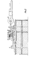
- Figure 1 shows a part sectional view of an embodiment of the present invention which comprises an electrical connector having a plug part and a socket part coupled together;
- Figure 2 shows a part sectional view of the electrica connector of Figure 1 wherein the plug part and the socket part are partly disconnected;
- Figure 3 shows a part sectional view of the electrica connector of Figures 1 and 2 wherein the plug part and the socket part are disconnected;
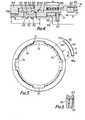
- Figure 4 shows a part sectional view of a second embodiment of the present invention;
- Figure 5 shows an end view of a coupling sleeve of the second embodiment of Figure 4;
- Figure 6 shows a sectional view of an arcuate segment of the second embodiment taken along lines A-A of Figure 5;
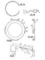
- Figures 7a and 7b show a spring for positioning between the coupling sleeve and the retaining sleeve;
- Figures 8a and 8b show a thrust washer provided with a ratchet means;
- Figure 9 shows an enlarged portion of an arm of the thrust washer in engagement with the plug part; and
- Figure 10 is a part sectional view of a third embodiment of the present invention.
- Referring firstly to Figure 1, a connector is shown in which a socket part 2 and a plug part 4 are coupled together. The socket part 2 is of circular cross-section and has a screw thread means, in this case a helical screw thread 6, formed on its outer periphery at one end. The socket part 2 houses a
moulded block 8 of insulating material, whichblock 8 provides support for a number ofconductive socket elements 10. The plug part 4 comprises aninner shell 12 which is positioned within the socket part 2 and which houses a moulded block 14 of insulating material. The block 14 supportselectrical connector pins 16 corresponding to theconductive socket elements 10 of the socket part 2. As shown in Figure 1, theelectrical pins 16 are received by theconductive socket elements 10 thereby effecting electrical connection between the socket part 2 and the plug part 4. Arubber sealing gasket 18 is provided on the inner surface of the socket part 2 to provide a seal between the socket part 2 and the plug part 4 when they are coupled together. - A
coupling sleeve 20 is captive on the outer surface of the plug part 4 and has an internal screw thread means 22 which is defined by a plurality of elongate movable orsliding parts 24 having hemispherical ends. Thesliding parts 24 are slidably located in radially extending apertures formed in thecoupling sleeve 20 and they define a helical path which corresponds to the helical screw thread 6. The radially inward ends of thesliding parts 24 engage roots of the helical screw thread 6 when the socket part 2 and the plug part 4 are connected. The radially outward ends of thesliding parts 24 butt against aretaining sleeve 26 which is slidably mounted on thecoupling sleeve 20. Hence, when theretaining sleeve 26 is in the position shown in Figure 1, thesliding parts 24 are restrained from sliding radially outwardly. Theretaining sleeve 26 is urged to rest at this position by means of aspring 28, for example a compression spring, located between thecoupling sleeve 20 and theretaining sleeve 26. - A thrust washer 30 (to be described in detail later with reference to Figures 8a, 8b and 9) is sandwiched between a stop 32 formed on the outer periphery of the
inner shell 12, and aflange 34, which flange forms part of thecoupling sleeve 20. The thrust washer 30 urges the socket part 2 towards the plug part 4 when the two parts are coupled together. This arrangement enables thecoupling sleeve 20 to be captive on the plug part 4 so that it is free to rotate about the longitudinal axis of the connector. It will be appreciated that the foregoing arrangement is such that thecoupling sleeve 20 can be screwed on to or off the socket part 2 by rotating the coupling sleeve about the longitudinal axis of the connector in the appropriate direction. Hence, when the socket part 2 and the plug part 4 are to be connected, it is clear that thecoupling sleeve 20 can be screwed on to the socket part 2 thereby causing the thrust washer 30 to urge theinner sleeve 12 towards the socket part 2 so that the end of theinner sleeve 12 butts up against therubber sealing gasket 18. - The
thrust washer 30 is operative to permit rotation of thecoupling sleeve 20 in the screw on direction with relative ease while being operative, by way of a ratchet-like means (to be described later), to resist rotation in the unscrew direction. - Referring now to Figure 2, disconnection of the socket part 2 and the plug part 4 of the connector will be described. A
lanyard 36 is attached to theretaining sleeve 26 in the manner shown. When a force is exerted on thelanyard 36 in the direction of arrow A, theretaining sleeve 26 slides, relati\e to thecoupling sleeve 20 and thesliding parts 24, in the direction of arrow A against the action of thespring 28. The distance of travel of the retainingsleeve 26 is limited by means of a retainingpin 38 which passes through anelongate hole 39 in the retainingsleeve 26, whichhole 39 defines the distance through which the retainingsleeve 26 may be moved. As can be seen in Figure 2, the retainingsleeve 26 has been moved in the direction of arrow A so that one end of thehole 39 butts up against thepin 38, and ahelical recess 40, formed in the retaining sleeve 26 (shown in Figure 1 as a pair of semi-circular recesses), is located adjacent to the slidingparts 24. The slidingparts 24 are then free to slide radially outwardly when made to do so by shearing forces (due to the exertion of the force on the lanyard 36) between the hemispherical ends of the slidingparts 24 and the side of the helical screw thread 6. As a result of this operation, the slidingparts 24 slide away from the helical screw thread 6 and the radially outward hemispherical ends are received by thehelical recess 40, thereby enabling the plug part 4 and the socket part 2 to be disconnected. - Referring now to Figure 3, the socket part 2 and the plug part 4 are shown to be disconnected, but a force is still being exerted on the
lanyard 36 so that the retainingsleeve 26 remains in the appropriate position for disengagement of the socket part 2 and the plug part 4. Due to the separation of the socket part 2 and the plug part 4, thethrust washer 30 expands and so causes theflange 34 of thecoupling sleeve 20 to butt up against a retainingring 42 located on the outer periphery of theinner shell 12, thereby preventing thecoupling sleeve 20 from becoming detached from theinner shell 12. - So that the sliding
parts 24 do not fall out of thecoupling sleeve 20, when the plug part 4 and the socket part 2 are disconnected, the slidingparts 24 are each provided with aflange 44 which can engage with aseat 46 located in respective radially extending apertures. - The connector is provided with an indexing means so that the
electrical pin 16 of the plug part 4 can be aligned withcorrect socket elements 10 of the socket part 2 when the two parts are to be connected. The indexing means comprises aguide 48 which projects from the periphery of the plug part 4, and arecess 50 situated on the periphery of the socket part 2, whichrecess 50 receives the guide when the two parts are coupled together. - It will be understood that although the
coupling sleeve 20 and the slidingparts 24, of the above described arrangement, form a part of the plug part 4, alternative arrangement can be envisaged without departing from the scope of the present invention, for example, one in which the coupling sleeve and sliding parts are located on the socket part. - Referring now to Figure 4, a part sectional view of electrical connector according to a second embodiment of the present invention is shown. The electrical connector comprises a
socket part 52 and aplug part 54 shown connected together. Thesocket part 52 has anexternal screw thread 56 on its outer periphery. - A
coupling sleeve 62 is captive on the outer surface of theplug part 54 and has an internal screw thread means which is defined by six arcuatemovable parts 58 havingprojections 59 on their inwardly curved surface. Theprojections 59, which although shown as having a hemispherical cross section may alternatively be trapezoidal in cross section, form part of a helical thread. Theprojections 59 of the sixmovable parts 58 together make up a double thread having a triple thread start. Themovable parts 58 also haveprojections 60 on their outwardly curved surface. In this embodiment, theprojections 60 are in the form of a pair of annular ribs which butt against a retaining sleeve 61 when thesocket part 52 and theplug part 54 are connected together. - Each of the
arcuate segments 58 is disposed in a circunferentially extending aperture in thecoupling sleeve 62. The retaining sleeve 61 is mounted on the outer surface of thecoupling sleeve 62 and is slidable relative thereto in a direction parallel to the longitudinal axis of the connector and is rotatable about the longitudinal axis of the connector. The retaining sleeve 61 has a pair ofrecesses 63 which correspond to theprojections 60 of thearcuate segments 58. Hence, when the retaining sleeve 61 is slid in the direction of an arrow A, a face 64 of the retaining sleeve 61 butts up against a corresponding edge of thecoupling sleeve 62, and therecesses 63 are then in such a position that therecesses 63 can receive theprojections 60 thereby enabling thesocket part 52 and theplug part 54 to be disconnected in a similar manner to that described with reference to the first embodiment. - The retaining sleeve 61 is located in a radial direction by means of an
end cap 65 which is screwed and locked to thecoupling sleeve 62 by means of ascrew thread 65a. The outer circumferential surface of theend cap 65 is knurled thereby facilitating an improved hand gripping surface. - A spring 68 (to be described in further detail later) is disposed between the retaining sleeve 61 and the
coupling sleeve 62. Thespring 68 urges the retaining sleeve 61 towards the position shown in Figure 4 so that in the absence of a force in the direction of the arrow A, the retaining sleeve 61 restrains thearcuate segments 58 from moving radially outwardly and hence the electrical connector remains connected. - A thrust washer 66 (to be further described later) is located between the
coupling sleeve 62 and theplug part 54. The thrust washer is provided with a ratchet-like means operative to permit rotation of thecoupling sleeve 62 in one direction with a lower torque than that required to effect rotation of the coupling sleeve in the opposite direction. - A
circlip 67 is located into a recess formed in thecoupling sleeve 62, which circlip serves to secure thethrust washer 66, and thecoupling sleeve 62 in position. - A
lanyard attachment ring 90 is positioned within a radially inner surface of the retaining sleeve 61 as shown in Figure 4. Alanyard 70 is fixed to thelanyard attachment ring 90. An end portion 69 of the retaining sleeve 61 is spun over so as to captivate thelanyard attachment ring 90 whilst allowing the retaining sleeve 61 to rotate relative to thering 90. This ensures that thelanyard 70 always remains in the same attitude relative to theplug part 54. - Referring now to Figure 5, an end view of the
coupling sleeve 62 is shown taken from the direction of an arrow B of Figure 4. Thecoupling sleeve 62 has an inwardly directedflange 71 which has fourslots 72 disposed along its circumference, which slots allow thethrust washer 66 and thecirclip 67 to be put into position. - As can be seen from Figure 5, the
coupling sleeve 62 has six circumferentially extendingapertures 73 which correspond in size to thearcuate segments 58. Each of theapertures 73 has a pair of opposite slopingsides 74 which cooperate with a pair of slopingsides 74a of thearcuate segment 58 so as to limit inward radial movement of thesegment 58 when disposed within theapertures 73 of thecoupling sleeve 62. - Figure 7a shows a plan view and Figure 7b shows a side elevational view of the
spring 68. Thespring 68 may be formed from, for example, piano wire and may consist of five lobes, each lobe having a pair of slopingsurfaces surfaces - The above described arrangement has the advantage that the
arcuate segments 58 for use therein can be manufactured more easily. For example, thesegments 58 can ee cut from an annular shaped brass ring after theprojections arcuate segment 58 in this manner enables their thickness in a radial direction to be significantly reduced and hence the thickness of thecoupling sleeve 62 can also be reduced. This results in an overall reduction in the overall radial dimension of the electrical connector. - The use of
arcuate segments 58 has the advantage that twisting of thesegments 58 within theapertures 73 is eliminated or at least reduced thereby increasing the life of the connector. Further, the risk of thesegments 58 becoming jammed is eliminated or reduced. - By locating the
lanyard attachment ring 90 on the radially inner surface of the retaining sleeve 61, unhampered hand access to the end cap 64 is possible thereby enabling the plug parts of the electrical connector to be secured onto thesocket part 52 more easily. Further, by allowing relative rotation of the retaining sleeve 61 with respect to thelanyard attachment ring 68, thelanyard 70 is prevented from becoming tangled with the cable of theplug part 54. - By forming the
projections 59 in the form of a double thread with a triple thread start enables theplug part 54 to be connected to thesocket part 52 with less than 180° turn by hand. - Figures 8a and 8b respectively show end and side elevational views of the thrust washer 66 (also equivalent to the
thrust washer 30 of Figures 1 to 3). Fourelongate arms 80 are located around the outer periphery of anannular washer part 81 to form a ratchet-like means but any number of arms may be provided in alternative embodiments. Eacharm 80 is attached to theannular washer part 81 at one end, and at the end remote from the attached end, there is disposed a restraining portion ordetent 82. As can be seen from Figure 8a, the restrainingportion 82 is arcuate in shape and is formed integrally with thearm 80. Alternatively, the restrainingportion 82 can be triangular in shape, the precise shape and size being determined by the torque characteristics required. - Figure 9 shows an enlarged portion of one of the
arms 80 when in contact with theplug part 54. Theplug part 54 has a toothed edge on its outer edge which can be of the form shown in Figure 9. When thethrust washer 66 is in the position as shown in Figure 4, the restrainingportion 82 of thearms 80 engage with the toothed edge of theplug part 54. Thearms 80 are received by theslots 72 of thecoupling sleeve 62 and hence relative rotation between thethrust washer 66 and thecoupling sleeve 62 is restrained. - A similar toothed edge (not shown) is provided on the plug part 4 of the embodiment illustrated in Figures 1 to which edge co-operates with the
thrust washer 30 to provide the required rotation characteristics. - If a torque is exerted between the
plug part 54 and thecoupling sleeve 62 so as to urge them to rotate in the directions of the arrows A' and A" in Figure 9, the restrainingportions 82 slide over the toothed edge since the torque exerts a tensile force in thearms 80. However, when the torque urges relative rotation in a direction opposite to arrows At and A", a compressive force is exerted in thearms 80 and so relative rotation is resisted. - The
thrust washer coupling sleeve 62 is prevented from uncoupling if the connector is subjected to vibration. - The
arms 80 may be of differing lengths, thereby eliminating or reducing the number of resonant frequencies of vibration of thethrust washer 66. The lengths of thearms 80 are preferably such that vibrations over a wide frequency range will not cause thecoupling sleeve 62 to work loose. - The
annular washer part 81 may also act as a spring, shaped so as to urge thecirclip 67 and the face of theplug part 54 apart. - Referring to Figure 10, a part sectional view of an electrical connector according to a third embodiment of the present invention is shown. This embodiment is a modified version of the connector described with reference to Figure 4. In this embodment, the connector comprises a socket part 100 and a
plug part 101 shown disconnected. The socket part 100 has ascrew thread 102 on its outer periphery. - A
coupling sleeve 103 is captive on the outer surface of theplug part 101 and has an internal screw thread means which is defined by six arcuatemovable parts 104 similar to theparts 58 described with reference to Figure 4. The arcuatemovable parts 104 haveprojections 105 on their inwardly curved surface which form part of a helical thread and are shaped to engage roots of thescrew thread 102 when the parts of the connector are connected. - The
movable parts 104 also haveprojections 106 on their outwardly curved surface. In this embodiment, theprojections 106 are in the form of annular ribs which butt against a retainingsleeve 107 when theplug part 101 and the socket part 100 are connected. Each of theparts 104 is disposed in a circumferentially extending aperture in thecoupling sleeve 103. The retainingsleeve 107 is mounted on thecoupling sleeve 103 and is slidable relative thereto in a direction parallel to the longitudinal axis of the connector and is rotatable about the longitudinal axis of the connector. The retainingsleeve 107 has a singleannular recess 108 corresponding to one of theprojections 106. When the retainingsleeve 107 is slid in the direction of arrow A, therecess 108 can be moved into a position (as indicated by dotted lines) such that it can receive theprojection 106 thereby enabling the socket and plug to be disconnected in a similar manner as that described with reference to the connector of Figure 4. - By having one
annular groove 108 instead of two as per the embodiment illustrated in Figure 4, themovable part 104 can be situated further forward in the connector thereby enabling thread engagement to take place ahead of electrical connector engagement when the plug and socket are connected together. - The retaining
sleeve 107 is located by means of anend cap 109 which is screwed and locked to thecoupling sleeve 103 by means of ascrew thread 110. - A
return spring 111, in the form of a wave washer spring, is disposed between the retainingsleeve 107 and thecoupling sleeve 103. Thespring 111, which is equivalent to thespring 68 illustrated in Figure 4, urges the retainingsleeve 107 towards the position shown in Figure 10 so that in the absence of a force in the direction of the arrow A, the retainingsleeve 107 restrains theparts 104 from moving radially outwardly. In order to connect theplug 101 and the socket 100, thecoupling sleeve 103 and the retainingsleeve 107 are rotated about the longitudinal axis of the connector so that when thehelical thread 105 engages with thethread 102, the plug and socket are drawn together. - A
thrust washer 112, equivalent to thewasher 66 described with reference to Figures 8a, 8b and 9, is located between thecoupling sleeve 103 and theplug part 101. Thethrust washer 112 is provided with the ratchet-like means operative to permit rotation of thecoupling sleeve 103 in one direction with a lower torque than that required to effect rotation of the sleeve in the opposite direction. Thewasher 112 therefore operates as an anti-vibration locking device which prevents the plug and socket unscrewing and becoming disconnected due to vibration. - A
circlip 113 is located in a recess formed in theplug part 101, which circlip serves to secure thethrust washer 112, and thecoupling sleeve 103 in position. - A
lanyard attachment ring 114 is positioned within a radially inner surface of the retainingsleeve 107 as shown in Figure 10. Thering 114 operates in a similar way to thering 90 illustrated in Figure 4. - A plurality of elongate continuity springs 115 are located on the periphery of the
plug part 101 to provide electrical continuity between theplug 101 and the socket 100 when connected.
Claims (15)
Applications Claiming Priority (4)
| Application Number | Priority Date | Filing Date | Title |
|---|---|---|---|
| GB8407800 | 1984-03-26 | ||
| GB848407800A GB8407800D0 (en) | 1984-01-12 | 1984-03-26 | Electrical connectors |
| GB08432478A GB2158657B (en) | 1984-01-12 | 1984-12-21 | Quick-release electrical connector |
| GB8432478 | 1984-12-21 |
Publications (2)
| Publication Number | Publication Date |
|---|---|
| EP0157542A2 true EP0157542A2 (en) | 1985-10-09 |
| EP0157542A3 EP0157542A3 (en) | 1987-01-14 |
Family
ID=26287514
Family Applications (1)
| Application Number | Title | Priority Date | Filing Date |
|---|---|---|---|
| EP85301942A Withdrawn EP0157542A3 (en) | 1984-03-26 | 1985-03-20 | Electrical connectors |
Country Status (2)
| Country | Link |
|---|---|
| EP (1) | EP0157542A3 (en) |
| GB (1) | GB2158301A (en) |
Cited By (3)
| Publication number | Priority date | Publication date | Assignee | Title |
|---|---|---|---|---|
| EP0311338A3 (en) * | 1987-10-05 | 1990-07-04 | Interconnection Products Incorporated | Electrical connector retaining ratchet |
| US10340631B1 (en) | 2018-06-15 | 2019-07-02 | Kunshan Amphenol Zhengri Electronics Co., Ltd. | Coupling structure of cable connector |
| CN110661138A (en) * | 2018-06-28 | 2020-01-07 | 昆山安费诺正日电子有限公司 | Cable connector butt joint structure |
Families Citing this family (1)
| Publication number | Priority date | Publication date | Assignee | Title |
|---|---|---|---|---|
| KR102205924B1 (en) * | 2016-04-04 | 2021-01-21 | 라디알 | Connection system with bayonet-type locking device configured to allow quick disconnect operation |
Family Cites Families (8)
| Publication number | Priority date | Publication date | Assignee | Title |
|---|---|---|---|---|
| FR1464746A (en) * | 1965-11-16 | 1967-01-06 | Deutsch Co | Electrical connector for instant-release mobiles |
| US3594700A (en) * | 1969-08-20 | 1971-07-20 | Pyle National Co | Electrical connector with threaded coupling nut lock |
| US3971614A (en) * | 1972-11-03 | 1976-07-27 | Akzona Incorporated | Electrical connector with means for maintaining a connected condition |
| US3917373A (en) * | 1974-06-05 | 1975-11-04 | Bunker Ramo | Coupling ring assembly |
| US4030789A (en) * | 1974-06-14 | 1977-06-21 | U.S. Philips Corporation | Method of manufacturing an electric discharge tube |
| US4109990A (en) * | 1977-05-26 | 1978-08-29 | The Bendix Corporation | Electrical connector assembly having anti-decoupling mechanism |
| US4279458A (en) * | 1979-07-23 | 1981-07-21 | The Bendix Corporation | Releasing electrical connector |
| US4500153A (en) * | 1981-11-09 | 1985-02-19 | Matrix Science Corporation | Self-locking electrical connector |
-
1985
- 1985-03-20 EP EP85301942A patent/EP0157542A3/en not_active Withdrawn
- 1985-03-22 GB GB08507499A patent/GB2158301A/en not_active Withdrawn
Cited By (4)
| Publication number | Priority date | Publication date | Assignee | Title |
|---|---|---|---|---|
| EP0311338A3 (en) * | 1987-10-05 | 1990-07-04 | Interconnection Products Incorporated | Electrical connector retaining ratchet |
| US10340631B1 (en) | 2018-06-15 | 2019-07-02 | Kunshan Amphenol Zhengri Electronics Co., Ltd. | Coupling structure of cable connector |
| EP3582338A1 (en) * | 2018-06-15 | 2019-12-18 | Kunshan Amphenol Zhengri Electronics Co., Ltd. | Coupling structure of cable connector |
| CN110661138A (en) * | 2018-06-28 | 2020-01-07 | 昆山安费诺正日电子有限公司 | Cable connector butt joint structure |
Also Published As
| Publication number | Publication date |
|---|---|
| GB2158301A (en) | 1985-11-06 |
| EP0157542A3 (en) | 1987-01-14 |
| GB8507499D0 (en) | 1985-05-01 |
Similar Documents
| Publication | Publication Date | Title |
|---|---|---|
| EP0150936B1 (en) | Electrical connectors | |
| US4046451A (en) | Connector for coaxial cable with annularly corrugated outer conductor | |
| US4703988A (en) | Self-locking electric connector | |
| EP2950401B1 (en) | Electrical connector | |
| US4235498A (en) | Electrical connector with locking means | |
| US5181860A (en) | Electrical connector with rotatable locking ring | |
| EP0495467B1 (en) | Self-flaring connector for coaxial cable having a helically corrugated outer conductor | |
| US4629272A (en) | Electrical connector assembly with anti-rotation latch mechanism | |
| US4749251A (en) | Connector locking system | |
| USRE31995E (en) | Enhanced detent guide track with dog-leg | |
| US4595251A (en) | Coupling mechanism for connectors | |
| US4277125A (en) | Enhanced detent guide track with dog-leg | |
| US4808123A (en) | Self-locking strain-relief end bell for electrical connector assembly | |
| JPS598034B2 (en) | Electrical connector with bayonet retainer | |
| US9142914B2 (en) | Push lock electrical connector | |
| US4820184A (en) | Electrical connector retaining ratchet | |
| US4564255A (en) | Strain relief device for an electrical plug connector | |
| EP3582338B1 (en) | Coupling structure of cable connector | |
| US20190221969A1 (en) | Rf connector for an rf module | |
| US4241969A (en) | Locking plug | |
| US4726782A (en) | Anti-decoupling device for an electrical connector | |
| US4390222A (en) | Lanyard release/umbilical electrical connector | |
| US4717351A (en) | Redundant electrical connector release | |
| GB2158301A (en) | Electrical connectors | |
| EP0026556B1 (en) | Lanyard release/umbilical electrical connector |
Legal Events
| Date | Code | Title | Description |
|---|---|---|---|
| PUAI | Public reference made under article 153(3) epc to a published international application that has entered the european phase |
Free format text: ORIGINAL CODE: 0009012 |
|
| AK | Designated contracting states |
Designated state(s): AT BE CH DE FR IT LI LU NL SE |
|
| PUAL | Search report despatched |
Free format text: ORIGINAL CODE: 0009013 |
|
| AK | Designated contracting states |
Kind code of ref document: A3 Designated state(s): AT BE CH DE FR IT LI LU NL SE |
|
| 17P | Request for examination filed |
Effective date: 19870619 |
|
| RAP1 | Party data changed (applicant data changed or rights of an application transferred) |
Owner name: AB ELECTRONIC COMPONENTS LIMITED |
|
| 17Q | First examination report despatched |
Effective date: 19881121 |
|
| STAA | Information on the status of an ep patent application or granted ep patent |
Free format text: STATUS: THE APPLICATION IS DEEMED TO BE WITHDRAWN |
|
| 18D | Application deemed to be withdrawn |
Effective date: 19890404 |
|
| RIN1 | Information on inventor provided before grant (corrected) |
Inventor name: DUNCAN, WILLIAM CHAMBERS WILSON |