EP0156807B1 - Vehicle and method of operating same - Google Patents
Vehicle and method of operating same Download PDFInfo
- Publication number
- EP0156807B1 EP0156807B1 EP84901386A EP84901386A EP0156807B1 EP 0156807 B1 EP0156807 B1 EP 0156807B1 EP 84901386 A EP84901386 A EP 84901386A EP 84901386 A EP84901386 A EP 84901386A EP 0156807 B1 EP0156807 B1 EP 0156807B1
- Authority
- EP
- European Patent Office
- Prior art keywords
- wheel assembly
- wheel assemblies
- relative
- wheel
- assemblies
- Prior art date
- Legal status (The legal status is an assumption and is not a legal conclusion. Google has not performed a legal analysis and makes no representation as to the accuracy of the status listed.)
- Expired - Lifetime
Links
Images


Classifications
-
- A—HUMAN NECESSITIES
- A61—MEDICAL OR VETERINARY SCIENCE; HYGIENE
- A61G—TRANSPORT, PERSONAL CONVEYANCES, OR ACCOMMODATION SPECIALLY ADAPTED FOR PATIENTS OR DISABLED PERSONS; OPERATING TABLES OR CHAIRS; CHAIRS FOR DENTISTRY; FUNERAL DEVICES
- A61G5/00—Chairs or personal conveyances specially adapted for patients or disabled persons, e.g. wheelchairs
- A61G5/06—Chairs or personal conveyances specially adapted for patients or disabled persons, e.g. wheelchairs with obstacle mounting facilities, e.g. for climbing stairs, kerbs or steps
- A61G5/061—Chairs or personal conveyances specially adapted for patients or disabled persons, e.g. wheelchairs with obstacle mounting facilities, e.g. for climbing stairs, kerbs or steps for climbing stairs
-
- A—HUMAN NECESSITIES
- A61—MEDICAL OR VETERINARY SCIENCE; HYGIENE
- A61G—TRANSPORT, PERSONAL CONVEYANCES, OR ACCOMMODATION SPECIALLY ADAPTED FOR PATIENTS OR DISABLED PERSONS; OPERATING TABLES OR CHAIRS; CHAIRS FOR DENTISTRY; FUNERAL DEVICES
- A61G5/00—Chairs or personal conveyances specially adapted for patients or disabled persons, e.g. wheelchairs
- A61G5/06—Chairs or personal conveyances specially adapted for patients or disabled persons, e.g. wheelchairs with obstacle mounting facilities, e.g. for climbing stairs, kerbs or steps
- A61G5/063—Chairs or personal conveyances specially adapted for patients or disabled persons, e.g. wheelchairs with obstacle mounting facilities, e.g. for climbing stairs, kerbs or steps with eccentrically mounted wheels
- A61G5/065—Chairs or personal conveyances specially adapted for patients or disabled persons, e.g. wheelchairs with obstacle mounting facilities, e.g. for climbing stairs, kerbs or steps with eccentrically mounted wheels with three or more wheels mounted on a rotary cross member, e.g. spiders or spoked wheels with small wheels at the end of the spokes
Definitions
- the present invention relates to a method of operating a wheelchair or other vehicle to climb a flight of steps.
- a wheelchair having front wheels mounted for rotation relative to a seat of the wheelchair about a front axis which is fixed with respect to the seat and having rear wheels mounted on respective arms which can pivot relative to the seat to swing the rear wheels upwardly and downwardly relative to the seat.
- a first handwheel is provided at one side of the wheelchair for driving the front and rear wheels at that side of the wheelchair with a high transmission ratio.
- a second handwheel at the one side of the wheelchair is connected, via a belt drive, with a pulley attached to the arm which carries the rear wheel at that side of the wheelchair. The arm can be caused to swing relative to the seat by turning of the second hand wheel.
- third and fourth handwheels At the otherside ofthewheelchair,there are provided third and fourth handwheels.
- the third handwheel is drivingly connected with front and rear ground- engaging wheels at the same side of the wheelchair and the fourth handwheel is connected by a belt drive with the pivoted arm at the same side of the wheelchair.
- the wheelchair can be propelled backwards to a flight of stairs.
- the arms and rear wheels can then be pivoted upwardly to compensate for the elevation of the rear wheels which will occur when the rear wheels are driven onto the firsttread of the stairs. If the rearwheels are driven on to the second tread of the stairs before the front wheels are driven onto the first tread of the stairs, then the arms and rear wheels can be pivoted upwardly again by means of the second and fourth handwheels.
- a method of operating a vehicle to climb a flight of steps comprising a load-carrying body provided with front and rear wheel assemblies, wherein one of said wheel assemblies is moved onto a tread of the lowest step of said flight, the positional relation between the wheel assemblies and the body is varied concurrently with driving of the one wheel assembly onto the tread to compensate for the upward movement of the one wheel assembly and to maintain the attitude of the body substantially constant and wherein rotation of an element of said one wheel assembly is compared with rotation of an element of the otherwheel assembly and the difference determines the magnitude of the variation in the positional relation between the wheel assemblies and the body.
- a vehicle comprising a load-carrying body and front and rear wheel assemblies wherein one of said assemblies is movable upwardly and downwardly relative to the body when the body is in the normal attitude of use and there is provided control means for comparing the relation between rotation of an element of the frontwheel assemblyand rotation of an element of the rear wheel assembly and controlling upward and downward movement of said one wheel assemby in accordance with said relation so as to maintain the attitude of the body substantially constant.
- the invention has been devised primarily in relation to a vehicle which is a wheelchair. However, the invention may be applied to other wheeled vehicles where analogous features can be used.
- the present invention provides a vehicle in which a load-carrying surface which is horizontal in normal use on a horizontal floor can remain horizontal during ascent of or descent of at least some flights of stairs.
- said elements of the front and rear wheel assemblies may rotate at the same speed. If one of the wheel assemblies then travels down a step whilst the other wheel assembly moves a relatively short distance along the level ground, one of said elements will rotate at a higher speed than the other during movement of the one wheel assembly down the step and this change in the relative speeds of the elements is used to control relative movement of the seat and other wheel assembly so that the attitude of the seat remains approximately constant.
- Said one assembly may be movable along a predetermined path relative to the seat, the relation between the path and the seat being such that, when the seat is in the normal attitude of use, movement of said one assembly in one direction along the path can be resolved into an upward component and a horizontal component away from the other wheel assembly and movement in the opposite direction along the path can be resolved into a downward component and a horizontal component towards the other wheel assembly.
- the effective wheel base of the vehicle is extended when the one assembly moves upwardly relative to the seat.
- the front and rear wheel assemblies are preferably both restrained against turning about upright axes.
- the vehicle may include a further wheel assembly comprising a wheel which can turn about an upright axis and which can be moved upwardly and downwardly relative to an adjacent one of the front and rear wheel assemblies.
- the wheel of the further wheel assembly is preferably free to turn about its upright axis. Two such further wheel assemblies could be provided.
- the further wheel assembly may be provided with means for restraining rotation of a carrier of an adjacent one of the front and rear wheel assemblies when the further wheel assembly is lowered relative to said one of the front and rear wheel assemblies.
- the wheelchair illustrated in the drawings includes a load-supporting body 10 which includes a seat 11, a backrest 12 and foot rests 13.
- the wheelchair further comprises a pair of front wheel assemblies 14 and 15 disposed one adjacent to each side of the body 10.
- a castor 16 which can be raised and lowered relative to the body 10 and the front wheel assemblies 14 and 15 by means of a handle and a screw and nut mechanism (not shown).
- the wheelchair further comprises a pair of rear wheel assemblies 17 and 18 mounted on a common member 19 for movement upwardly and downwardly relative to the body 10.
- the member 19 is connected with the body for pivoting relative thereto about an axis 20 which lies just below the seat 11 and above the front wheel assemblies 14 and 15.
- the front wheel assembly 15 includes a carrier 21 mounted for unlimited rotation relative to the body 10 about an axis 22 which is common to the front wheel assemblies and is parallel to the axis 20.
- a plurality of wheels is mounted on the carrier 21 for rotation relative thereto about respective axes which are spaced apart and from the axis 22 and are parallel to the axis 22.
- the wheels on the carrier 21 are identified by the reference numerals 23, 24 and 25 and their axes are indicated by the reference numerals 26, 27 and 28 respectively. These axes are spaced 100 mm to 150 mm from the axis 22.
- the brake element is omitted from Figure 1 but shown in Figure 3.
- the axis of curvature of the element 29 coincides with the axis 22 of the carrier.
- the brake element is supported in the centre of the carrier by a bearing which provides for rotation of the carrier relative to the brake element.
- the brake element is connected with the body 10 by a linkage (not shown) which normally restrains rotation of the brake element relative to the body about the axis 20 but which enables the brake element to be adjusted angularly about that axis relative to the body within a predetermined range, for example 45°.
- the front wheel assembly 14 is constructed and arranged in the same manner as the wheel assembly 15.
- the brake elements of the wheel assemblies 14 and 15 may be connected with the body 10 by a common linkage which ensures that the brake elements undergo the same angular adjustment.
- Each of the rear wheel assemblies 17 and 18 comprises a plurality of wheels, three in the example illustrated, and a carrier arranged in the same manner as the wheels and carrier of the wheel assembly 15. However, the rear wheel assemblies do not have brake elements corresponding to the element 29.
- Control means is provided for controlling pivoting of the member 19 relative to the body 10 according to the relation between rotation of the carriers of the front wheel assemblies 14 and 15 and rotation of the carriers of the rear wheel assemblies 17 and 18.
- the control means includes a rotatable control element in the form of a sprocket 30 connected by a linkage with the member 19.
- This linkage comprises a slide 31 which is slidable upwardly and downwardly on a guide 32 fixed to the body 10 and a link 33 extending between and pivotally connected with the member 19 and the slide 31.
- the sprocket 30 is mounted on the slide 31 for rotation relative thereto about an axis parallel to the axis 20.
- a further sprocket 34 also is similarly mounted on the slide.
- the control means further comprises an endless flexible element in the form of a chain 35 which extends from the sprocket 30 around a sprocket 36 fixed on the carrier 21, then around a sprocket 37 on a front drive shaft 38, around the sprocket 34, around a sprocket 39 on a rear drive shaft 40, around an idler sprocket 41 on the body 10 and then back to the sprocket 30.
- the rear drive shaft 40 is mounted for rotation relative to the body 10 about the axis 20 and the front drive shaft 38 is mounted for rotation relative to the body about an axis parallel to the axis 20 and spaced somewhat forwardly therefrom.
- the front drive shaft lies above the axis 22 of the front wheel assemblies and the idler sprocket 41 lies to the rear of that axis.
- a further endless flexible element in the form of a chain 42 extends around a further sprocket on the rear drive shaft 40 and around a sprocket which is fast with the carrier of the rear wheel assembly 18.
- the drive chains and sprockets are duplicated on the other side of the wheelchair, so that the carriers of the two rear wheel assemblies are caused to rotate together at a speed which bears a fixed relation to the speed of the rear drive shaft 40, provided the member 19 does not turn about the axis 20.
- the carriers of the front wheel assemblies 14 and 15 also are caused to rotate together at a speed which bears a fixed relation to the speed of the front drive shaft 38.
- Drive means including an electric motor 43 and a gearbox 44 is provided for driving the front drive shaft 38 and the rear drive shaft 40 together or independently of one another, as required.
- the motor 43 is used for ascending or descending a step or a flight of steps but is not used for driving the wheelchair along level ground.
- the drive means comprises a further motor 45 connected by suitable drive means with the wheels of the rear wheel assemblies 17 and 18.
- This drive means may include a belt or chain which extends around pulleys or sprockets fixed with respect to the wheels or may include a gear train.
- a combination of a gear train and belt and pulley drive may be provided for transmitting torque from the motor 45 to the wheels of the rear wheel assemblies.
- each rear wheel assembly will run on the ground and the other two wheels of each rear wheel assembly will idle. Thus, substantial torque will be transmitted to only one wheel of each rear wheel assembly.
- Separate drive belts may be provided for the three wheels of each rear wheel assembly, or a common drive belt may be provided. In place of a belt, there may be used a chain and reference is herein to a drive belt should be construed accordingly.
- the motor 45 can be energized independently of the motor 43.
- the castor 16 For travel of the wheelchair on a level surface, the castor 16 projects downwardly below the wheels of the front wheel assemblies 14 and 15 so that the wheels of the latter are clear of the ground.
- the wheelchair is driven by the motor 45.
- a known mechanism for causing differential rotation of wheels of the rear wheel assemblies For steering of the wheelchair, there may be provided a known mechanism for causing differential rotation of wheels of the rear wheel assemblies.
- the wheelchair When a flight of steps is to be ascended, the wheelchair is positioned with the rear wheel assemblies near to the lowest step, as shown in Figure 4.
- the castor 16 is raised relative to the body 10 so that the wheels of the front wheel assemblies 14 and 15 rest on the ground.
- the motor 45 is de-energized so that this motor acts as a brake, restraining rotation of the wheels of the rear wheel assemblies unless turning of the carriers of the wheel assemblies occurs.
- the motor 43 is energized to drive the rear drive shaft 40 only.
- This drive shaft is driven in a direction to draw the chain 35 in a direction from the sprocket 34 and to pass chain around the idler 41 towards the sprocket 30.
- the length of chain between the rear drive shaft and the sprocket 34 is reduced, so that the slide 31 is drawn up the guide 32.
- This motion is transmitted by the link 33 to the member 19 which is therefore pivoted upwardly relative to the body 10. In this way, the rear wheel assemblies 17 and 18 are raised relative to the body 10 and the front wheel assemblies.
- Rotation of the rear drive shaft also causes the carrier of each rear wheel assembly to turn about the axis of that wheel which is adjacent to the lowest step and in a direction to move the uppermost of the rear wheels towards the tread of the first step.
- This wheel moves onto the tread of the first step and, if driving of the rear shaft is continued, the carrier of the rear wheel assembly then turns about the axis of this wheel to move the third wheel onto the tread of the second step.
- the rear wheel assemblies move upwardly to the tread of a step, whilst the front wheel assemblies are on a horizontal surface spaced away from the steps and the front drive shaft is not driven, there is no substantial movement of the chain 35 around the sprockets 36 and 37. Accordingly, the rear wheel assemblies are automatically raised relative to the body 10 and front wheel assemblies so that the attitude of the seat 11 is not changed significantly.
- the brake elements 29 Prior to ascent of the steps, the brake elements 29 are adjusted so that the flat surface 48 of each element is inclined to the horizontal and faces somewhat rearwardly.
- the gearbox 44 is adjusted to transmit drive from the motor 43 to both of the drive shafts 38 and 40. Whilst both drive shafts are driven by the motor, the slide 31 remains in the position to which it has been set and movement of the member 19 relative to the body 10 is prevented.
- Each carrier of the wheelchair is moved around the axis of a wheel on that carrier, the wheel bearing against adjacent surfaces of a tread and a riser.
- Each wheel of the front wheel assemblies is braked as it moves through an arc lying generally above the axis 22.
- the wheel When each of these wheels moves through an arc adjacent to the flat 48 of the brake element 29 and lying below and rearwardly of the axis 22, the wheel is un- braked and the associated carrier can turn about the axis of that wheel without the wheel itself participating in the motion.
- the wheel may be subjected to a predetermined braking torque, rather than being completely un- braked.
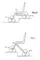
- the chair may be used to climb a step forwardly, as illustrated in Figure 7.
- the front drive shaft alone is driven initially to cause the front wheel assembly to climb the step and to cause the member 19 concurrently to pivot downwardly, thereby lowering the rear wheel assemblies.
- drive of the front drive shaft is discontinued and the rear drive shaft is driven by cause the rear wheel assemblies to climb the step and to cause the member 19 to pivot upwardly to its initial position with respect to the body 10.
- the wheelchair For descent of a flight of steps, the wheelchair is brought to rest with the front wheel assemblies close to the uppermost step.
- the brake elements 29 are adjusted so that the flat surfaces 48 thereof are horizontal and face downwardly.
- the front drive shaft 38 alone is then driven to cause the front wheel assemblies to roll down the first and second steps.
- the member 19 is pivoted upwardly to raise the rear wheel assemblies relative to the body 10 and thereby maintain the seat 11 horizontal.
- the action of the brake element 29 ensures that each wheel of the front wheel assemblies rolls down a riser onto a tread of the steps and then remains close to that riser whilst the associated carrier moves about the axis of that wheel to bring a further wheel into contact with the next lowermost riser.
- the motors 43 and 45 may be energised from batteries (not shown) mounted on the body 10 and partly occupying the space between the rear wheel assemblies. If required, separate motors may be provided for driving the front and rear shafts. Alternatively, a single motor may be provided for driving the wheelchair during normal travel and for driving the front and rear shafts. There may be provided on the body 10 limit switches which respond to pivoting of the member 19 by providing signals which adjust the gearbox 44.
- the vertical component of the permitted movement of the rear wheel assemblies relative to the body 10 is at least 150 mm and is preferably at least 300 mm.
- the member 19 may be biased with respect to the body 10 to a predetermined position intermediate the positions to which it can be pivoted.
- the biasing means may comprise a spring acting between the member 19 and the body 10. When the member is in this predetermined position, the front and rear wheel assemblies can support the wheelchair on a horizontal surface with the seat 11 substantially horizontal.
- each wheel When the wheelchair is ascending a flight of steps, each wheel is moved into contact with a corresponding tread of the steps with the axis of that wheel approximately vertically above the point of first contact between the wheel and the tread.
- the backrest 12 and a rear part 46 of the seat can pivot together relative to the seat part 11 and body 10 between the erected position shown in Figure 1 and a folded position in which the backrest lies adjacent to the foot rests 13. These also can be folded relative to the body 10.
- the axis 47 about which the backrest can be folded lies just below the level of and to the rear of the seat part 11 and is parallel to the axis 20.
- the castor 16 is disposed between the front wheel assemblies 14 and 15, the castor could alternatively be positioned near to the rear of the wheelchair.
- pivoting about this axis may be controlled for steering of the wheelchair.
- the wheelchair may include a steering control operable by the user to pivot the wheel about its vertical axis.
- means may be provided for driving the wheel, as an alternative to driving the rear wheel assemblies when the wheelchair is travelling along the horizontal surface.
- the means for driving the wheel will include a motor and a transmission train for transmitting torque from the motor to the wheel.
- the transmission train includes a telescopic, generally upright shaft and the steering control also includes a telescopic, parallel shaft, the wheel 16 being carried on an axle which can be moved upwardly and downwardly relative to the front wheel assemblies so that the front wheel assemblies can be lifted clear of the ground when the wheelchair is to run of the wheel 16 and can be lowered to the ground when the wheel 16 is to be clear of the ground and the wheelchair is to run on the front wheel assemblies.
- a sliding carrier may be provided on the frame for moving the wheel 16 upwardly and downwardly.
- Driving of the wheels of the rear wheel assemblies in this manner is useful during the climbing of a flight of steps, since the rearwheel assemblies will be driven to the riser of each step.
- the limited torque transmitted from the motor 45 would be insufficient to cause the rear wheel assemblies to climb a riser.
- Drive from the motor 43 to each of the shafts 38 and 40 may be through a respective clutch and associated gearbox.
- the user can select either of the shafts to be driven by the motor.
- the wheelchair may comprise a single motor, clutches being provided for transmitting drive selectively to the front drive shaft, to the rear drive shaft and to a driven wheel or to driven wheels. There may be associated with each clutch a gearbox.
Abstract
Description
- From a first aspect, the present invention relates to a method of operating a wheelchair or other vehicle to climb a flight of steps.
- In DE-A-2,165,452, there is disclosed a wheelchair having front wheels mounted for rotation relative to a seat of the wheelchair about a front axis which is fixed with respect to the seat and having rear wheels mounted on respective arms which can pivot relative to the seat to swing the rear wheels upwardly and downwardly relative to the seat. A first handwheel is provided at one side of the wheelchair for driving the front and rear wheels at that side of the wheelchair with a high transmission ratio. A second handwheel at the one side of the wheelchair is connected, via a belt drive, with a pulley attached to the arm which carries the rear wheel at that side of the wheelchair. The arm can be caused to swing relative to the seat by turning of the second hand wheel. At the otherside ofthewheelchair,there are provided third and fourth handwheels. The third handwheel is drivingly connected with front and rear ground- engaging wheels at the same side of the wheelchair and the fourth handwheel is connected by a belt drive with the pivoted arm at the same side of the wheelchair. By means of the first and third handwheels,- the wheelchair can be propelled backwards to a flight of stairs. By means of the second and fourth handwheels, the arms and rear wheels can then be pivoted upwardly to compensate for the elevation of the rear wheels which will occur when the rear wheels are driven onto the firsttread of the stairs. If the rearwheels are driven on to the second tread of the stairs before the front wheels are driven onto the first tread of the stairs, then the arms and rear wheels can be pivoted upwardly again by means of the second and fourth handwheels.
- In operation of the wheelchair disclosed in DE-A-2,165,452 by the occupant of the wheelchair to climb a flight of stairs, tilting of the seat cannot be avoided. The occupant can turn either the first and third handwheels together or the second and fourth handwheels. Adjustment of the angular position of the arms can be carried out intermittently only. A further disadvantage is that the occupant of the wheelchair must judge the required degree of angular movement of the arms. This is not easy, inappropriate adjustment may reduce the stability of the wheelchair on a flight of stairs.
- According to the first aspect of the present invention, there is provided a method of operating a vehicle to climb a flight of steps, the vehicle comprising a load-carrying body provided with front and rear wheel assemblies, wherein one of said wheel assemblies is moved onto a tread of the lowest step of said flight, the positional relation between the wheel assemblies and the body is varied concurrently with driving of the one wheel assembly onto the tread to compensate for the upward movement of the one wheel assembly and to maintain the attitude of the body substantially constant and wherein rotation of an element of said one wheel assembly is compared with rotation of an element of the otherwheel assembly and the difference determines the magnitude of the variation in the positional relation between the wheel assemblies and the body.
- According to a second aspect of the invention, there is provided a vehicle comprising a load-carrying body and front and rear wheel assemblies wherein one of said assemblies is movable upwardly and downwardly relative to the body when the body is in the normal attitude of use and there is provided control means for comparing the relation between rotation of an element of the frontwheel assemblyand rotation of an element of the rear wheel assembly and controlling upward and downward movement of said one wheel assemby in accordance with said relation so as to maintain the attitude of the body substantially constant.
- Upward movement of one wheel assembly relative to the other through a distance of 150 mm is sufficient to maintain the body substantially horizontal when the other wheel assembly moves down a moderate step.
- The invention has been devised primarily in relation to a vehicle which is a wheelchair. However, the invention may be applied to other wheeled vehicles where analogous features can be used.
- The present invention provides a vehicle in which a load-carrying surface which is horizontal in normal use on a horizontal floor can remain horizontal during ascent of or descent of at least some flights of stairs.
- When the vehicle travels along level ground, said elements of the front and rear wheel assemblies may rotate at the same speed. If one of the wheel assemblies then travels down a step whilst the other wheel assembly moves a relatively short distance along the level ground, one of said elements will rotate at a higher speed than the other during movement of the one wheel assembly down the step and this change in the relative speeds of the elements is used to control relative movement of the seat and other wheel assembly so that the attitude of the seat remains approximately constant.
- Said one assembly may be movable along a predetermined path relative to the seat, the relation between the path and the seat being such that, when the seat is in the normal attitude of use, movement of said one assembly in one direction along the path can be resolved into an upward component and a horizontal component away from the other wheel assembly and movement in the opposite direction along the path can be resolved into a downward component and a horizontal component towards the other wheel assembly. With this arrangement, the effective wheel base of the vehicle is extended when the one assembly moves upwardly relative to the seat.
- The front and rear wheel assemblies are preferably both restrained against turning about upright axes.
- The vehicle may include a further wheel assembly comprising a wheel which can turn about an upright axis and which can be moved upwardly and downwardly relative to an adjacent one of the front and rear wheel assemblies. The wheel of the further wheel assembly is preferably free to turn about its upright axis. Two such further wheel assemblies could be provided.
- The further wheel assembly may be provided with means for restraining rotation of a carrier of an adjacent one of the front and rear wheel assemblies when the further wheel assembly is lowered relative to said one of the front and rear wheel assemblies.
- An example of a wheelchair embodying the second aspect of the invention and which is used in a method according to the first aspect will now be described, with reference to the accompanying drawings, wherein:-
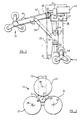
- FIGURE 1 shows diagrammatically a perspective view of the wheelchair;
- FIGURE 2 shows diagrammatically certain parts of the wheelchair, as seen from one side;
- FIGURE 3 shows on an enlarged scale a front wheel assemby omitted from Figure 2; and
- FIGURES 4 to 6 represent diagrammatically configurations of the wheelchair assumed under different circumstances.
- The wheelchair illustrated in the drawings includes a load-supporting
body 10 which includes aseat 11, abackrest 12 and foot rests 13. The wheelchair further comprises a pair offront wheel assemblies body 10. At an intermediate position, there is mounted on the body acastor 16 which can be raised and lowered relative to thebody 10 and the front wheel assemblies 14 and 15 by means of a handle and a screw and nut mechanism (not shown). The wheelchair further comprises a pair ofrear wheel assemblies common member 19 for movement upwardly and downwardly relative to thebody 10. Themember 19 is connected with the body for pivoting relative thereto about anaxis 20 which lies just below theseat 11 and above the front wheel assemblies 14 and 15. - The
front wheel assembly 15 includes acarrier 21 mounted for unlimited rotation relative to thebody 10 about anaxis 22 which is common to the front wheel assemblies and is parallel to theaxis 20. A plurality of wheels, three in the example illustrated, is mounted on thecarrier 21 for rotation relative thereto about respective axes which are spaced apart and from theaxis 22 and are parallel to theaxis 22. In Figure 3, the wheels on thecarrier 21 are identified by thereference numerals reference numerals axis 22. There is positioned between thewheels brake element 29 which is a sector of a body of revolution, preferably of a cylinder. The brake element is omitted from Figure 1 but shown in Figure 3. The axis of curvature of theelement 29 coincides with theaxis 22 of the carrier. The brake element is supported in the centre of the carrier by a bearing which provides for rotation of the carrier relative to the brake element. The brake element is connected with thebody 10 by a linkage (not shown) which normally restrains rotation of the brake element relative to the body about theaxis 20 but which enables the brake element to be adjusted angularly about that axis relative to the body within a predetermined range, for example 45°. - The
front wheel assembly 14 is constructed and arranged in the same manner as thewheel assembly 15. The brake elements of the wheel assemblies 14 and 15 may be connected with thebody 10 by a common linkage which ensures that the brake elements undergo the same angular adjustment. - Each of the rear wheel assemblies 17 and 18 comprises a plurality of wheels, three in the example illustrated, and a carrier arranged in the same manner as the wheels and carrier of the
wheel assembly 15. However, the rear wheel assemblies do not have brake elements corresponding to theelement 29. - Control means is provided for controlling pivoting of the
member 19 relative to thebody 10 according to the relation between rotation of the carriers of thefront wheel assemblies rear wheel assemblies sprocket 30 connected by a linkage with themember 19. This linkage comprises aslide 31 which is slidable upwardly and downwardly on aguide 32 fixed to thebody 10 and alink 33 extending between and pivotally connected with themember 19 and theslide 31. Thesprocket 30 is mounted on theslide 31 for rotation relative thereto about an axis parallel to theaxis 20. A further sprocket 34 also is similarly mounted on the slide. - The control means further comprises an endless flexible element in the form of a
chain 35 which extends from thesprocket 30 around asprocket 36 fixed on thecarrier 21, then around asprocket 37 on afront drive shaft 38, around the sprocket 34, around asprocket 39 on arear drive shaft 40, around an idler sprocket 41 on thebody 10 and then back to thesprocket 30. Therear drive shaft 40 is mounted for rotation relative to thebody 10 about theaxis 20 and thefront drive shaft 38 is mounted for rotation relative to the body about an axis parallel to theaxis 20 and spaced somewhat forwardly therefrom. The front drive shaft lies above theaxis 22 of the front wheel assemblies and the idler sprocket 41 lies to the rear of that axis. - A further endless flexible element in the form of a
chain 42 extends around a further sprocket on therear drive shaft 40 and around a sprocket which is fast with the carrier of therear wheel assembly 18. The drive chains and sprockets are duplicated on the other side of the wheelchair, so that the carriers of the two rear wheel assemblies are caused to rotate together at a speed which bears a fixed relation to the speed of therear drive shaft 40, provided themember 19 does not turn about theaxis 20. The carriers of the front wheel assemblies 14 and 15 also are caused to rotate together at a speed which bears a fixed relation to the speed of thefront drive shaft 38. - Drive means including an
electric motor 43 and agearbox 44 is provided for driving thefront drive shaft 38 and therear drive shaft 40 together or independently of one another, as required. Themotor 43 is used for ascending or descending a step or a flight of steps but is not used for driving the wheelchair along level ground. The drive means comprises afurther motor 45 connected by suitable drive means with the wheels of therear wheel assemblies motor 45 to the wheels of the rear wheel assemblies. Generally, one wheel of each rear wheel assembly will run on the ground and the other two wheels of each rear wheel assembly will idle. Thus, substantial torque will be transmitted to only one wheel of each rear wheel assembly. Separate drive belts may be provided for the three wheels of each rear wheel assembly, or a common drive belt may be provided. In place of a belt, there may be used a chain and reference is herein to a drive belt should be construed accordingly. Themotor 45 can be energized independently of themotor 43. - For travel of the wheelchair on a level surface, the
castor 16 projects downwardly below the wheels of thefront wheel assemblies motor 45. For steering of the wheelchair, there may be provided a known mechanism for causing differential rotation of wheels of the rear wheel assemblies. When a flight of steps is to be ascended, the wheelchair is positioned with the rear wheel assemblies near to the lowest step, as shown in Figure 4. Thecastor 16 is raised relative to thebody 10 so that the wheels of thefront wheel assemblies motor 45 is de-energized so that this motor acts as a brake, restraining rotation of the wheels of the rear wheel assemblies unless turning of the carriers of the wheel assemblies occurs. - The
motor 43 is energized to drive therear drive shaft 40 only. This drive shaft is driven in a direction to draw thechain 35 in a direction from the sprocket 34 and to pass chain around the idler 41 towards thesprocket 30. The length of chain between the rear drive shaft and the sprocket 34 is reduced, so that theslide 31 is drawn up theguide 32. This motion is transmitted by thelink 33 to themember 19 which is therefore pivoted upwardly relative to thebody 10. In this way, therear wheel assemblies body 10 and the front wheel assemblies. Rotation of the rear drive shaft also causes the carrier of each rear wheel assembly to turn about the axis of that wheel which is adjacent to the lowest step and in a direction to move the uppermost of the rear wheels towards the tread of the first step. This wheel moves onto the tread of the first step and, if driving of the rear shaft is continued, the carrier of the rear wheel assembly then turns about the axis of this wheel to move the third wheel onto the tread of the second step. As the rear wheel assemblies move upwardly to the tread of a step, whilst the front wheel assemblies are on a horizontal surface spaced away from the steps and the front drive shaft is not driven, there is no substantial movement of thechain 35 around thesprockets body 10 and front wheel assemblies so that the attitude of theseat 11 is not changed significantly. - Prior to ascent of the steps, the
brake elements 29 are adjusted so that theflat surface 48 of each element is inclined to the horizontal and faces somewhat rearwardly. When wheels of the rear wheel assemblies have reached the tread of the second step, thegearbox 44 is adjusted to transmit drive from themotor 43 to both of thedrive shafts slide 31 remains in the position to which it has been set and movement of themember 19 relative to thebody 10 is prevented. Each carrier of the wheelchair is moved around the axis of a wheel on that carrier, the wheel bearing against adjacent surfaces of a tread and a riser. Each wheel of the front wheel assemblies is braked as it moves through an arc lying generally above theaxis 22. When each of these wheels moves through an arc adjacent to the flat 48 of thebrake element 29 and lying below and rearwardly of theaxis 22, the wheel is un- braked and the associated carrier can turn about the axis of that wheel without the wheel itself participating in the motion. Alternatively, the wheel may be subjected to a predetermined braking torque, rather than being completely un- braked. - When the wheels of the
rear wheel assemblies slide 31 is driven down theguide 32, thereby returning themember 19 to its initial position and lowering the rear wheel assemblies relative to thebody 10. The attitude of theseat 11 remains substantially unchanged throughout the procedure. - In a case where a single step is to be climbed, a similar procedure is followed but the
member 19 is pivoted upwardly through a smaller angle, again to maintain the seat substantially horizontal. - It is envisaged that the chair may be used to climb a step forwardly, as illustrated in Figure 7. In this case, the front drive shaft alone is driven initially to cause the front wheel assembly to climb the step and to cause the
member 19 concurrently to pivot downwardly, thereby lowering the rear wheel assemblies. When the rear wheel assemblies reach the riser, drive of the front drive shaft is discontinued and the rear drive shaft is driven by cause the rear wheel assemblies to climb the step and to cause themember 19 to pivot upwardly to its initial position with respect to thebody 10. - For descent of a flight of steps, the wheelchair is brought to rest with the front wheel assemblies close to the uppermost step. The
brake elements 29 are adjusted so that theflat surfaces 48 thereof are horizontal and face downwardly. Thefront drive shaft 38 alone is then driven to cause the front wheel assemblies to roll down the first and second steps. Concurrently, themember 19 is pivoted upwardly to raise the rear wheel assemblies relative to thebody 10 and thereby maintain theseat 11 horizontal. When the front wheel assemblies have descended two steps, drive is applied to both the front and rear drive shafts and descent of the steps is continued. The action of thebrake element 29 ensures that each wheel of the front wheel assemblies rolls down a riser onto a tread of the steps and then remains close to that riser whilst the associated carrier moves about the axis of that wheel to bring a further wheel into contact with the next lowermost riser. - When the front wheel assemblies have reached the bottom of the flight of steps, drive to the front drive shaft is discontinued. Driving of the rear drive shaft then causes the rear wheel assemblies to complete descent of the steps and causes the
member 19 to pivot downwardly relative to thebody 10 so that the seat remains horizontal. Once all of the wheel assemblies have reached the bottom of the flight of steps, energisation of themotor 43 is terminated, thecastor 16 is lowered to raise the front wheel assemblies from the ground and themotor 45 is energised to drive the wheelchair away from the steps. - The
motors body 10 and partly occupying the space between the rear wheel assemblies. If required, separate motors may be provided for driving the front and rear shafts. Alternatively, a single motor may be provided for driving the wheelchair during normal travel and for driving the front and rear shafts. There may be provided on thebody 10 limit switches which respond to pivoting of themember 19 by providing signals which adjust thegearbox 44. - It will be understood that reference herein to the
seat 11 remaining horizontal do not mean that in all cases the seat will be precisely horizontal. Differences in the relation between the size of risers and treads of different steps will result in minor differences in the attitude of the seat as steps are ascended or descended but these differences will not be sufficient to impair significantly stability of the wheelchair or the comfort of the occupant. The vertical component of the permitted movement of the rear wheel assemblies relative to thebody 10 is at least 150 mm and is preferably at least 300 mm. - It will be noted that, when the wheels of the front wheel assemblies and the wheels of the rear wheel assemblies are rolling on horizontal surfaces, upwards and downwards adjustment of the rear wheel assemblies is prevented by the control means.
- The
member 19 may be biased with respect to thebody 10 to a predetermined position intermediate the positions to which it can be pivoted. The biasing means may comprise a spring acting between themember 19 and thebody 10. When the member is in this predetermined position, the front and rear wheel assemblies can support the wheelchair on a horizontal surface with theseat 11 substantially horizontal. - When the wheelchair is ascending a flight of steps, each wheel is moved into contact with a corresponding tread of the steps with the axis of that wheel approximately vertically above the point of first contact between the wheel and the tread.
- The
backrest 12 and arear part 46 of the seat can pivot together relative to theseat part 11 andbody 10 between the erected position shown in Figure 1 and a folded position in which the backrest lies adjacent to the foot rests 13. These also can be folded relative to thebody 10. The axis 47 about which the backrest can be folded lies just below the level of and to the rear of theseat part 11 and is parallel to theaxis 20. - Although, in the example illustrated, the
castor 16 is disposed between thefront wheel assemblies - In a case where pivoting of the
wheel 16 about its vertical axis is controlled by a steering control, means may be provided for driving the wheel, as an alternative to driving the rear wheel assemblies when the wheelchair is travelling along the horizontal surface. The means for driving the wheel will include a motor and a transmission train for transmitting torque from the motor to the wheel. Preferably, the transmission train includes a telescopic, generally upright shaft and the steering control also includes a telescopic, parallel shaft, thewheel 16 being carried on an axle which can be moved upwardly and downwardly relative to the front wheel assemblies so that the front wheel assemblies can be lifted clear of the ground when the wheelchair is to run of thewheel 16 and can be lowered to the ground when thewheel 16 is to be clear of the ground and the wheelchair is to run on the front wheel assemblies. A sliding carrier may be provided on the frame for moving thewheel 16 upwardly and downwardly. - There may be provided means for transmitting limited torque from the
motor 45 to the wheels of therear wheel assemblies motor 45 would be insufficient to cause the rear wheel assemblies to climb a riser. - Drive from the
motor 43 to each of theshafts - If the invention is applied to a vehicle other than a wheelchair, there would be provided in place of the seat a load platform. Features hereinbefore mentioned as optional features of the wheelchair may be incorporated in such a vehicle.
Claims (9)
Priority Applications (1)
| Application Number | Priority Date | Filing Date | Title |
|---|---|---|---|
| AT84901386T ATE60707T1 (en) | 1983-09-09 | 1984-03-28 | WHEELCHAIR AND HOW TO USE. |
Applications Claiming Priority (2)
| Application Number | Priority Date | Filing Date | Title |
|---|---|---|---|
| GB08324213A GB2126540B (en) | 1982-09-10 | 1983-09-09 | Stairclimbing vehicles |
| PCT/GB1984/000103 WO1985001206A1 (en) | 1983-09-09 | 1984-03-28 | Vehicle and method of operating same |
Publications (2)
| Publication Number | Publication Date |
|---|---|
| EP0156807A1 EP0156807A1 (en) | 1985-10-09 |
| EP0156807B1 true EP0156807B1 (en) | 1991-02-06 |
Family
ID=10548552
Family Applications (1)
| Application Number | Title | Priority Date | Filing Date |
|---|---|---|---|
| EP84901386A Expired - Lifetime EP0156807B1 (en) | 1983-09-09 | 1984-03-28 | Vehicle and method of operating same |
Country Status (8)
| Country | Link |
|---|---|
| US (1) | US4645222A (en) |
| EP (1) | EP0156807B1 (en) |
| JP (1) | JPS61501611A (en) |
| AT (1) | ATE60707T1 (en) |
| AU (1) | AU2731084A (en) |
| DE (1) | DE3484107D1 (en) |
| GB (1) | GB2126540B (en) |
| WO (1) | WO1985001206A1 (en) |
Cited By (2)
| Publication number | Priority date | Publication date | Assignee | Title |
|---|---|---|---|---|
| CN107433969A (en) * | 2016-05-26 | 2017-12-05 | 哈尔滨小神童科技开发有限责任公司 | Electronic manned climbing machine |
| CN108715193A (en) * | 2018-05-30 | 2018-10-30 | 安徽知之信息科技有限公司 | Stairs device is climbed by a kind of trailing type house keeper robot |
Families Citing this family (44)
| Publication number | Priority date | Publication date | Assignee | Title |
|---|---|---|---|---|
| GB2126540B (en) * | 1982-09-10 | 1986-07-16 | Robert Hester | Stairclimbing vehicles |
| SE8403635L (en) * | 1984-07-09 | 1986-01-23 | Bjorn Ake Ortenheim | STEPING TRANSPORTATION |
| GB8515992D0 (en) * | 1985-06-25 | 1985-07-31 | Hester R | Wheelchair |
| GB2186847B (en) * | 1985-06-25 | 1989-07-19 | Robert Hester | Wheelchair and method of operating same |
| CA1275296C (en) * | 1987-05-04 | 1990-10-16 | Pierre Decelles | Climbing and descending vehicle |
| GB2257097A (en) * | 1991-06-29 | 1993-01-06 | Yorkshire Regional Health Auth | Folding chair |
| US5507358A (en) * | 1993-06-04 | 1996-04-16 | Kabushiki Kaisha Daikin Seisakusho | Stair climbing vehicle |
| DK132893D0 (en) * | 1993-11-26 | 1993-11-26 | Frankie Thomsen | WHEELCHAIR MACHINE: A MOTORIZED MACHINE FOR TRANSPORTING WHEELCHAIRS WITH USERS IN, PRIOR TO STEP TRANSPORTATION |
| DE19733033A1 (en) * | 1997-07-31 | 1999-02-18 | Daimler Benz Ag | Single-seat motor vehicle |
| DE29720939U1 (en) * | 1997-11-26 | 1999-04-01 | Bock Orthopaed Ind | Safety device for stair climbing devices |
| USD409120S (en) * | 1998-04-08 | 1999-05-04 | Ferno-Washington, Inc. | Stair chair |
| AUPP469998A0 (en) * | 1998-07-16 | 1998-08-06 | Ferno Australia Pty Ltd | Device for facilitating the loading of stretcher undercarriages into ambulances |
| GB2346851B (en) | 1998-07-31 | 2001-04-04 | Ferno Washington | Chairs |
| GB2351264A (en) * | 1999-06-22 | 2000-12-27 | British Aerospace | Wheelchair having means to assist ingress and egress of a disabled person from a vehicle |
| WO2001074652A2 (en) * | 2000-04-04 | 2001-10-11 | Irobot Corporation | Wheeled platforms |
| GB2414392B (en) * | 2001-06-29 | 2006-01-18 | Ferno Uk Ltd | Patient transport chair |
| PL356789A1 (en) * | 2002-10-22 | 2004-05-04 | Janusz Karpiński | A vehicle |
| US6926287B1 (en) | 2003-09-15 | 2005-08-09 | Bernard P. Maher | Stroller assembly |
| CA2559909A1 (en) * | 2004-04-08 | 2005-10-20 | Levo Ag Wohlen | Wheelchair with a middle wheel drive, in particular raising whellchair |
| ITTO20050451A1 (en) * | 2005-06-28 | 2006-12-29 | Cubed S R L D | MOTORIZED WHEEL TRIPOD GROUP, IN PARTICULAR FOR A WHEELCHAIR, AND WHEELCHAIR PROVIDED WITH THIS WHEEL GROUP. |
| WO2007079346A2 (en) * | 2005-12-30 | 2007-07-12 | Olsen Christopher J | Articulated wheel assemblies and vehicles therewith |
| US20070222165A1 (en) * | 2006-03-24 | 2007-09-27 | Hope Thomas L | Multi-wheeled hub and cargo-carrying apparatuses comprising same |
| US8413752B2 (en) * | 2006-10-06 | 2013-04-09 | Irobot Corporation | Robotic vehicle |
| US7784570B2 (en) | 2006-10-06 | 2010-08-31 | Irobot Corporation | Robotic vehicle |
| US8644991B2 (en) | 2006-10-06 | 2014-02-04 | Irobot Corporation | Maneuvering robotic vehicles |
| US7891446B2 (en) * | 2006-10-06 | 2011-02-22 | Irobot Corporation | Robotic vehicle deck adjustment |
| US8327960B2 (en) | 2006-10-06 | 2012-12-11 | Irobot Corporation | Robotic vehicle |
| US7654348B2 (en) * | 2006-10-06 | 2010-02-02 | Irobot Corporation | Maneuvering robotic vehicles having a positionable sensor head |
| US7669862B2 (en) * | 2007-04-27 | 2010-03-02 | Sterraclimb Llc | Foldable spider wheel for ascending and descending stairs |
| US7669861B2 (en) * | 2007-05-07 | 2010-03-02 | Vincent Dean Herreid | Stone block transporting crawler-climber |
| DE102008019688A1 (en) | 2008-04-14 | 2009-10-15 | Markus Dobler | Vehicle, particularly wheelchair, for closed overriding of stairs, is fitted on axles, where rotating bearing elements are provided with two axle journals, and wheels are arranged on axle journals |
| DE102008049440A1 (en) | 2008-09-29 | 2010-04-01 | Markus Dobler | Stair-climbing vehicle i.e. wheelchair, for overriding on steps and/or stairs, has two brackets provided at ends of power transmission arm, respectively, adjustable in its length and actuated by clutch |
| GB2480069A (en) * | 2010-05-07 | 2011-11-09 | Abdulkarim Mohamed | Stair climbing wheel for baby carriage |
| EP2672942A4 (en) * | 2011-02-07 | 2016-12-14 | Mobility 2000 (Australia) Ltd | Step-climbing attachment for a wheeled chair |
| CN102941901B (en) * | 2012-11-12 | 2015-06-03 | 朱幕松 | Standing handrail type electric elevator vehicle carrying people to go up and down |
| CN103462750B (en) * | 2013-09-30 | 2015-12-23 | 河北联合大学 | Manned robot mechanism is used in rescue |
| US9452097B2 (en) * | 2014-03-31 | 2016-09-27 | Clive Lu | Electric mobility vehicle |
| CN104644353A (en) * | 2014-06-25 | 2015-05-27 | 何云勇 | Wheelchair facilitating upstairs and downstairs movement |
| CN104773235A (en) * | 2015-04-23 | 2015-07-15 | 朱幕松 | Folding type electric vehicle for carrying persons to get upstairs or downstairs |
| CN106137577B (en) * | 2016-07-15 | 2017-09-01 | 长安大学 | It is a kind of to realize self-service upper wheelchair downstairs |
| CN108514478B (en) * | 2018-05-14 | 2022-04-19 | 河南理工大学 | Novel climb electronic wheelchair of stair |
| FR3081816B1 (en) * | 2018-05-29 | 2021-09-17 | Arturo Mazzolini | OBSTACLE BREAKDOWN ASSISTANCE DEVICE FOR MANUALLY RAISING OR LOWERING A LOAD, AND LOAD INCLUDING SUCH A DEVICE |
| RU2688288C1 (en) * | 2019-02-04 | 2019-05-21 | Валерий Иванович Паутов | Stroller for people with disabilities in walking |
| US11737533B1 (en) * | 2022-01-12 | 2023-08-29 | John Jones | Hard-shell backpack with wheels |
Citations (1)
| Publication number | Priority date | Publication date | Assignee | Title |
|---|---|---|---|---|
| EP0100449A1 (en) * | 1982-07-07 | 1984-02-15 | Heinz Kluth | Wheel-chair for invalids |
Family Cites Families (17)
| Publication number | Priority date | Publication date | Assignee | Title |
|---|---|---|---|---|
| GB352705A (en) * | 1930-06-24 | 1931-07-16 | Alex Pascoo | Improvements in baby carriages and like vehicles |
| GB383203A (en) * | 1931-05-18 | 1932-11-10 | Joseph John Powers | Improvements in or relating to hand propelled vehicles, such as perambulators |
| GB657835A (en) * | 1949-02-28 | 1951-09-26 | Michael Sellati | Improvements in or relating to baby carriage suspensions |
| GB734048A (en) * | 1952-03-19 | 1955-07-20 | Ave Transp Mittel Holding A G | Undercarriage for vehicles designed to run over uneven ground and, in particular up and down stairs |
| GB874903A (en) * | 1959-10-27 | 1961-08-16 | Ilon B E | Improvements in or relating to carriages |
| GB1046444A (en) * | 1962-04-24 | 1966-10-26 | Neville Edward Hale | Vehicles for travel over horizontal and inclined surfaces |
| US3196970A (en) * | 1963-05-17 | 1965-07-27 | Dale E Brenner | Stair-climbing wheel chair |
| US3241848A (en) * | 1963-12-27 | 1966-03-22 | John F Flory | Stair-climbing vehicle |
| US3283839A (en) * | 1965-03-02 | 1966-11-08 | Ronald K Brown | Stair-climbing wheel chair |
| US3346268A (en) * | 1965-08-27 | 1967-10-10 | Robert W Richman | Vehicle with climbing wheels |
| SE348155B (en) * | 1968-04-22 | 1972-08-28 | Johnson & Co Handels Ab A | |
| DE2165452A1 (en) * | 1971-12-29 | 1973-07-05 | Fritz A Deutsch | ILLUSTRATION WITH UNLIMITED FREEDOM OF MOVEMENT |
| US3891229A (en) * | 1974-03-14 | 1975-06-24 | Orthokinetics Inc | Travel chair |
| GB1430714A (en) * | 1974-06-18 | 1976-04-07 | Linsley E P | Stair ascending of descending cart |
| GB1491555A (en) * | 1975-01-21 | 1977-11-09 | Ramby Inc | Stair climbing tracked vehicle |
| CH632201A5 (en) * | 1978-09-05 | 1982-09-30 | Frei U Mobil Werke Ag | STAIRWAY ACCESSORIES, ESPECIALLY FOR GOODS. |
| GB2126540B (en) * | 1982-09-10 | 1986-07-16 | Robert Hester | Stairclimbing vehicles |
-
1983
- 1983-09-09 GB GB08324213A patent/GB2126540B/en not_active Expired
-
1984
- 1984-03-28 EP EP84901386A patent/EP0156807B1/en not_active Expired - Lifetime
- 1984-03-28 US US06/731,110 patent/US4645222A/en not_active Expired - Fee Related
- 1984-03-28 DE DE8484901386T patent/DE3484107D1/en not_active Expired - Lifetime
- 1984-03-28 WO PCT/GB1984/000103 patent/WO1985001206A1/en active IP Right Grant
- 1984-03-28 AT AT84901386T patent/ATE60707T1/en not_active IP Right Cessation
- 1984-03-28 AU AU27310/84A patent/AU2731084A/en not_active Abandoned
- 1984-03-28 JP JP59501446A patent/JPS61501611A/en active Pending
Patent Citations (1)
| Publication number | Priority date | Publication date | Assignee | Title |
|---|---|---|---|---|
| EP0100449A1 (en) * | 1982-07-07 | 1984-02-15 | Heinz Kluth | Wheel-chair for invalids |
Cited By (2)
| Publication number | Priority date | Publication date | Assignee | Title |
|---|---|---|---|---|
| CN107433969A (en) * | 2016-05-26 | 2017-12-05 | 哈尔滨小神童科技开发有限责任公司 | Electronic manned climbing machine |
| CN108715193A (en) * | 2018-05-30 | 2018-10-30 | 安徽知之信息科技有限公司 | Stairs device is climbed by a kind of trailing type house keeper robot |
Also Published As
| Publication number | Publication date |
|---|---|
| GB8324213D0 (en) | 1983-10-12 |
| GB2126540B (en) | 1986-07-16 |
| ATE60707T1 (en) | 1991-02-15 |
| AU2731084A (en) | 1985-04-11 |
| GB2126540A (en) | 1984-03-28 |
| WO1985001206A1 (en) | 1985-03-28 |
| US4645222A (en) | 1987-02-24 |
| EP0156807A1 (en) | 1985-10-09 |
| DE3484107D1 (en) | 1991-03-14 |
| JPS61501611A (en) | 1986-08-07 |
Similar Documents
| Publication | Publication Date | Title |
|---|---|---|
| EP0156807B1 (en) | Vehicle and method of operating same | |
| EP0226628B1 (en) | Wheelchair and method of operating same | |
| US4898256A (en) | Stair-climbing wheelchair carrier with crawlers | |
| US4044850A (en) | Wheelchair | |
| US4566551A (en) | Stair-climbing conveyance | |
| KR101943180B1 (en) | Running gear and electric vehicles and toys equipping the same | |
| EP1738734A2 (en) | Powered tripod wheel assembly, in particular for a wheelchair, and wheelchair featuring such a wheel assembly | |
| US4674584A (en) | Stair-climbing wheelchair with stair step sensing means | |
| US4432425A (en) | Wheel chair | |
| US4108449A (en) | Stair-climbing wheelchair | |
| US4671369A (en) | Stair-climbing wheelchair with means for cushioning vertical movements thereof | |
| KR102046151B1 (en) | Electric drivr type wheelchair with stairs going up and down function | |
| WO1994007452A1 (en) | Stair transcending conveyance | |
| JPH0751319A (en) | Climbing motorized wheelchair | |
| CN111343956B (en) | Vehicle for crossing obstacle | |
| KR20030088947A (en) | The stair climbing robot and traveling method | |
| CN112249181A (en) | Crawler stair climbing machine | |
| WO2006103787A1 (en) | Traveling device | |
| CN110575327A (en) | Balance wheelchair | |
| GB2258202A (en) | "escalator apparatus" | |
| KR102381643B1 (en) | Lift apparatus for wheel chair | |
| JP2014024375A (en) | Step lifting apparatus | |
| CN211565873U (en) | Robot | |
| AU702926C (en) | Stair transcending conveyance | |
| JP5555953B2 (en) | Stair-climbing mobile vehicle |
Legal Events
| Date | Code | Title | Description |
|---|---|---|---|
| PUAI | Public reference made under article 153(3) epc to a published international application that has entered the european phase |
Free format text: ORIGINAL CODE: 0009012 |
|
| AK | Designated contracting states |
Designated state(s): AT BE CH DE FR LI LU NL SE |
|
| 17P | Request for examination filed |
Effective date: 19850927 |
|
| 17Q | First examination report despatched |
Effective date: 19870527 |
|
| GRAA | (expected) grant |
Free format text: ORIGINAL CODE: 0009210 |
|
| AK | Designated contracting states |
Kind code of ref document: B1 Designated state(s): AT BE CH DE FR LI LU NL SE |
|
| PG25 | Lapsed in a contracting state [announced via postgrant information from national office to epo] |
Ref country code: SE Effective date: 19910206 Ref country code: NL Effective date: 19910206 Ref country code: LI Effective date: 19910206 Ref country code: CH Effective date: 19910206 Ref country code: BE Effective date: 19910206 Ref country code: AT Effective date: 19910206 |
|
| REF | Corresponds to: |
Ref document number: 60707 Country of ref document: AT Date of ref document: 19910215 Kind code of ref document: T |
|
| PGFP | Annual fee paid to national office [announced via postgrant information from national office to epo] |
Ref country code: AT Payment date: 19910313 Year of fee payment: 8 |
|
| REF | Corresponds to: |
Ref document number: 3484107 Country of ref document: DE Date of ref document: 19910314 |
|
| PGFP | Annual fee paid to national office [announced via postgrant information from national office to epo] |
Ref country code: SE Payment date: 19910320 Year of fee payment: 8 |
|
| PGFP | Annual fee paid to national office [announced via postgrant information from national office to epo] |
Ref country code: NL Payment date: 19910331 Year of fee payment: 8 |
|
| PGFP | Annual fee paid to national office [announced via postgrant information from national office to epo] |
Ref country code: LU Payment date: 19910403 Year of fee payment: 8 Ref country code: CH Payment date: 19910403 Year of fee payment: 8 |
|
| REG | Reference to a national code |
Ref country code: CH Ref legal event code: PL |
|
| ET | Fr: translation filed | ||
| NLV1 | Nl: lapsed or annulled due to failure to fulfill the requirements of art. 29p and 29m of the patents act | ||
| EPTA | Lu: last paid annual fee | ||
| PLBE | No opposition filed within time limit |
Free format text: ORIGINAL CODE: 0009261 |
|
| STAA | Information on the status of an ep patent application or granted ep patent |
Free format text: STATUS: NO OPPOSITION FILED WITHIN TIME LIMIT |
|
| 26N | No opposition filed | ||
| PG25 | Lapsed in a contracting state [announced via postgrant information from national office to epo] |
Ref country code: LU Free format text: LAPSE BECAUSE OF NON-PAYMENT OF DUE FEES Effective date: 19920328 |
|
| PGFP | Annual fee paid to national office [announced via postgrant information from national office to epo] |
Ref country code: FR Payment date: 19930331 Year of fee payment: 10 |
|
| PGFP | Annual fee paid to national office [announced via postgrant information from national office to epo] |
Ref country code: DE Payment date: 19930421 Year of fee payment: 10 |
|
| PG25 | Lapsed in a contracting state [announced via postgrant information from national office to epo] |
Ref country code: FR Effective date: 19941130 |
|
| PG25 | Lapsed in a contracting state [announced via postgrant information from national office to epo] |
Ref country code: DE Effective date: 19941201 |
|
| REG | Reference to a national code |
Ref country code: FR Ref legal event code: ST |