EP0156298B1 - Rack housing for user reconfigurable edp system - Google Patents
Rack housing for user reconfigurable edp system Download PDFInfo
- Publication number
- EP0156298B1 EP0156298B1 EP85103226A EP85103226A EP0156298B1 EP 0156298 B1 EP0156298 B1 EP 0156298B1 EP 85103226 A EP85103226 A EP 85103226A EP 85103226 A EP85103226 A EP 85103226A EP 0156298 B1 EP0156298 B1 EP 0156298B1
- Authority
- EP
- European Patent Office
- Prior art keywords
- panel
- frame
- pwas
- open
- housing
- Prior art date
- Legal status (The legal status is an assumption and is not a legal conclusion. Google has not performed a legal analysis and makes no representation as to the accuracy of the status listed.)
- Expired
Links
Images
Classifications
-
- H—ELECTRICITY
- H05—ELECTRIC TECHNIQUES NOT OTHERWISE PROVIDED FOR
- H05K—PRINTED CIRCUITS; CASINGS OR CONSTRUCTIONAL DETAILS OF ELECTRIC APPARATUS; MANUFACTURE OF ASSEMBLAGES OF ELECTRICAL COMPONENTS
- H05K7/00—Constructional details common to different types of electric apparatus
- H05K7/14—Mounting supporting structure in casing or on frame or rack
- H05K7/1422—Printed circuit boards receptacles, e.g. stacked structures, electronic circuit modules or box like frames
- H05K7/1424—Card cages
- H05K7/1425—Card cages of standardised dimensions, e.g. 19"-subrack
Definitions
- the present invention relates to rack housing for user reconfigurable EDP system.
- Modern data processing systems are constituted by electronic circuits mounted on a plurality of printed circuit boards (for the following identified with PWA that is "Printed Wired Artwork") housed in a box shaped frame having an open forehead and arranged therein on suitable parallel tracks.
- PWA printed Wired Artwork
- the tracks constitute a rack for the mechanical positioning of the several PWAs.
- the PWA singly or in sets, carry out the function of system central unit and of peripheral unit controllers.
- the frame forehead is open to allow the insertion of the several PWAs on the tracks and may be closed by a cover fixed by screws or by other fixing means such as the so-called "fasteners".
- Modern data processing systems are reconfigurable, that is allow to increase their performances and meet the specific needs of the user by the addition of electronic circuits.
- the frame is intended to contain a prefixed number of PWAs while the actually inserted PWAs vary from a minimum M ⁇ N up to N according to the specific needs of the user.
- the minimum number M of PWAs constitutes the minimum system configuration, that is a set of electronic circuits which may be tested and which is able to operate in a correct way according to minimum user requirements.
- the EDP systems are assembled in their minimum configuration, tested and packed, in order to be ready for the distribution, than stored.
- the system reconfiguration is performed at the user site by specialized technical people which adds PWAs to the system.
- the EDP systems are assembled in any possible configuration, tested, packed and stored.
- the reconfiguration operation must be easy, must not require particular devices and constructive complications which may increase the cost of the product and, especially, the removal and the damaging of the already installed PWAs owing to an uncareful handling must be avoided.
- This solution may undergo possible system reconfigurations effected by users, but the equipment assembling becomes longer and more complicated therefore causing a cost increase if compared with the cost of a similar equipment provided with a single cover for the whole rack housing.
- housing for user reconfigurable system object of the present invention as claimed where the open housing front is closed by a single cover, easy to be removed by the user, or by a plurality of covers each of them however covering a plurality of printed circuit boards and providing the selective access to preestablished housing rails and where removal of the printed circuit boards arranged on the remaining rails is prevented by a protection and stopping bar.
- the protection bar is provided with suitable cut-out portions in correspondence of the housing positions where the selective introduction of printed circuit boards is allowed and it is interposed between the frame and the cover so that its removal requires the cover removal.
- screws fixing the bar to the frame are of a kind requiring the use of a tool and they are preferably masked by the cover.
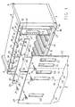
- Figure 1 shows in exploded perspective view a preferred embodiment of the invention.
- the rack housing of the invention consists of a box constituted by a rigid frame and a front panel 2 which can be removed.
- the frame is constituted by a lower panel 3, an upper panel 4, two side panels 5, 6 and a back panel 7.
- Some edges of the several panels present a L shaped bending for granting more stiffness to the unit and the panels are fixed to each other to form a unitary body, preferably by welding.
- the several panels constitute a rectangular parallelepiped shaped housing, frontally opened, and their four edges define a front plane.
- lower panel 3 is double L bent in correspondence of the front panel in order to present a laying flange 3A on the front plane and an horizontal foot 3B extending perpendicularly to the front plane for the whole width of the frame.
- upper panel 4 in correspondence of the front plane, presents a L shaped bending towards the external of the frame in order to obtain a laying flange 4A in the front plane.
- the lower and upper panels bear a plurality of PWA tracks arranged parallel the one to the other and perpendicularly to the open frontal plane of the housing.
- Each track arranged on the lower panel corresponds to a track arranged on the upper panel in the same perpendicular plane.
- Each of such track is provided with a guiding groove intended to contain a PWA edge.
- the housing is, for instance, embodied with 8 lower tracks and 8 upper tracks, that is with 8 PWA locations and it can therefore contain up to 8 PWAs.
- Fig. 1 The several locations are identified in Fig. 1 by means of the upper tracks and are numbered from 11 to 18.
- the PWAs are inserted into the housing through the front by inserting the upper and lower edges of the PWAs into the groove of an upper track and a corresponding lower track, respectively.
- the back panel 7 is generally provided with connection sockets not shown, vertically arranged and intended to obtain the electrical connection with the PWAs inserted in the housing.
- the several PWAs constitutes a reconfigurable EDP system, where the PWA arranged for instance into locations 12, 14, 17, 18 must be present to constitute the basic system while locations 11, 13, 15, 16 may or may not contain PWAs to extend the system performances.
- a PWA acting as central unit or CPU can be arranged into location 12
- a PWA acting as working memory or MM can be arranged into locations 14
- two PWAs acting as controllers for peripheral units, such as disk units can be arranged into locations 17, 18.
- Some memory expansion PWAs can be optionally inserted into locations 11, 13 and PWAs acting as controllers of peripherals such as printers, connection terminals and transmission lines, etc., can be optionally inserted into locations 15, 16.
- the system basic PWAs are inserted into the housing during the manufacturing process and are kept in the housing by a protection and stopping ruler 20.
- Ruler 20 extends over the whole width of the rack housing and is fixed by screws 21, 22 to the flange 4A of upper panel 4.
- Screws 21, 22 are inserted into opening 24, 25 of the ruler and screwed in correspondent threaded housings 26, 27 of flange 4A.
- Screws 21, 22 are preferably tapered-head screws and opening 24, 25 are similarly tapered in order to house the heads of screws 21, 22 within ruler 20 thickness.
- ruler 20 When ruler 20 is positioned, it partially closes the front opening of the housing in correspondence of the upper tracks by the extension of its lower edge downwards, beyond flange 4A.
- Ruler 20 presents some notches or undercuttings 28,29,30,31 in correspondence of locations 11, 13, 16, 17 respectively, that is in correspondence of the reconfiguration and expansion PWA locations.
- the frame opening is closed by a front panel 2 extending for the whole width and height of the frame and overlapping ruler 20.
- Front panel 2 is fixed to the frame by means of knob screws 32, 33, 34 and by cogs 35, 36, 37, 38.
- the screws are inserted into corresponding openings of the front panel and screwed in corresponding threaded frame housings 39, 40, 41 getting through suitable openings 42, 43, 44 of ruler 20.
- Housings 45, 46, 47 are shown in the figure.
- the front panel When the front panel is fixed to the frame, it protects the PWAs arranged in the housing and prevents their removal irrespective of their location.
- Front panel 2 presents suitable openings such as 48, 49, 50, 51, 52 to allow the insertion of connection plugs into connection sockets mounted on the front edge of the PWA.
- Such connectors enable the connection, by cable, to peripheral units of the system.
- connection of a control keyboard and of a display screen to the central unit PWA is enabled; through openings 49, 50 the connection is allowed to optional peripherals to the optional PWAs which may be arranged into locations 15, 16 and, through openings 51, 52 the connection is allowed of basic peripheral of the system to the control PWAs arranged in locations 17, 18.
- the user can remove front panel 2 by unscrewing the screws 32, 33, 34 without using tool.
- Ruler undercuttings 28, 29, 30, 31 clearly display the several insertion positions and cut to the minimum the possible occurrence of mistakes.
- the front panel can be cut in two or more independent sections, each panel section assuring the protection and the retaining of a suitable group of PWAs.
- panel 2 of Fig. 1 can be cut into three sections 2A, 2B, 2C evidenced by hatched lines 54, 55.
- So panel 2A assure the retaining and the protection of the group of PWAs arranged into locations 11, 12, 13, 14.
- Panel 2B assures the retaining and the protection of the group of PWA arranged into locations 15,16 and panel 2C assures the retaining and the protection of the group of PWAs arranged into locations 17, 18.
- knob screw is not essential for the fixing of panel 2C as such panel protects some basic PWAs of the system.
- panel 2C and more generally a plurality of panels protecting some basic PWAs of the system may constitute, together with ruler 20, a single unit.
- the fixing means for ruler 20 and for the panels preferably suggested as tapered-head screws and knob screws, respectively, can clearly be substituted by equivalent fixing means provided they fundamentally differ for the ruler and for the panels and such as to require the use of different and more specialized tools for the ruler removal.
- knob screws preferred for the fixing of the panels can be substituted with slotted head screws which can be unscrewed and screwed by screwdrivers, coins or similar means.
- fixing screws of the ruler could be of specialized kind, which can be unscrewed and screwed only by means of wrenches, crosshead screwdriver, square-head, hexagonal-head, star-head-keys, etc.
Landscapes
- Engineering & Computer Science (AREA)
- Microelectronics & Electronic Packaging (AREA)
- Casings For Electric Apparatus (AREA)
- Structure Of Telephone Exchanges (AREA)
Description
- The present invention relates to rack housing for user reconfigurable EDP system.
- Modern data processing systems are constituted by electronic circuits mounted on a plurality of printed circuit boards (for the following identified with PWA that is "Printed Wired Artwork") housed in a box shaped frame having an open forehead and arranged therein on suitable parallel tracks.
- The tracks constitute a rack for the mechanical positioning of the several PWAs.
- The PWA, singly or in sets, carry out the function of system central unit and of peripheral unit controllers.
- The frame forehead is open to allow the insertion of the several PWAs on the tracks and may be closed by a cover fixed by screws or by other fixing means such as the so-called "fasteners". Modern data processing systems are reconfigurable, that is allow to increase their performances and meet the specific needs of the user by the addition of electronic circuits.
- This is made with the addition of PWAs in the frame.
- To this purpose the frame is intended to contain a prefixed number of PWAs while the actually inserted PWAs vary from a minimum M<N up to N according to the specific needs of the user.
- The minimum number M of PWAs constitutes the minimum system configuration, that is a set of electronic circuits which may be tested and which is able to operate in a correct way according to minimum user requirements.
- In the conventional manufacturing and distribution of such requirements the warehouse administration is affected by important cost problems. There are two approaches which may be followed.
- According to a first approach the EDP systems are assembled in their minimum configuration, tested and packed, in order to be ready for the distribution, than stored.
- The system reconfiguration, according to the user needs, is performed at the user site by specialized technical people which adds PWAs to the system.
- The cost of the specialized operation is high and does not conform to the technological trends of supplying products of the "plug" and play" type which do not require a specialized technical support for their installation.
- According to a second approach the EDP systems are assembled in any possible configuration, tested, packed and stored.
- In this case a configured model suitable for any user need is available, but this causes an high increase of the fixed store investments. Besides, in case the user needs evolve, the already installed system must be substituted or the specialized operation is again required. To overcome such inconvenient the embodiment has been recently suggested of systems where the reconfiguration can be performed by the user himself once provided with a system with the minimum configuration and the necessary additional PWAs.
- The reconfiguration operation must be easy, must not require particular devices and constructive complications which may increase the cost of the product and, especially, the removal and the damaging of the already installed PWAs owing to an uncareful handling must be avoided.
- It is known in the art, for instance from US Patents 4,334,261 and 4,301,494, that the open forehead of a rack housing for several PWAs can be closed by a plurality of cover plates, one for each PWA, fixed by knurled grips or fasteners.
- This solution may undergo possible system reconfigurations effected by users, but the equipment assembling becomes longer and more complicated therefore causing a cost increase if compared with the cost of a similar equipment provided with a single cover for the whole rack housing.
- In both the cases the user is not prevented from removing the already installed PWAs.
- Further the repetitive modularity of the cover plates described in the already mentioned patents can mislead the user in the reconfigurating operation.
- Such inconvenients are overcome by the rack. housing for user reconfigurable system object of the present invention as claimed where the open housing front is closed by a single cover, easy to be removed by the user, or by a plurality of covers each of them however covering a plurality of printed circuit boards and providing the selective access to preestablished housing rails and where removal of the printed circuit boards arranged on the remaining rails is prevented by a protection and stopping bar.
- The protection bar is provided with suitable cut-out portions in correspondence of the housing positions where the selective introduction of printed circuit boards is allowed and it is interposed between the frame and the cover so that its removal requires the cover removal.
- It is fixed to the frame by means of screws different from the ones fixing the cover so that the cover removal does not involve the bar removal.
- Further the screws fixing the bar to the frame are of a kind requiring the use of a tool and they are preferably masked by the cover.
- In this way a double protection is assured because any accidental removal of the bar without the previous cover removal is prevented.
- These and other features of the invention will appear clearly from the following description of a preferred form of embodiment and from the enclosed drawing where:
- Figure 1 shows in exploded perspective view a preferred embodiment of the invention.
- With reference to Fig. 1 the rack housing of the invention consists of a box constituted by a rigid frame and a
front panel 2 which can be removed. - The frame is constituted by a
lower panel 3, anupper panel 4, twoside panels - Some edges of the several panels present a L shaped bending for granting more stiffness to the unit and the panels are fixed to each other to form a unitary body, preferably by welding.
- The several panels constitute a rectangular parallelepiped shaped housing, frontally opened, and their four edges define a front plane.
- For illustrative purposes, it is particularly pointed out that
lower panel 3 is double L bent in correspondence of the front panel in order to present alaying flange 3A on the front plane and anhorizontal foot 3B extending perpendicularly to the front plane for the whole width of the frame. - Likewise
upper panel 4, in correspondence of the front plane, presents a L shaped bending towards the external of the frame in order to obtain a layingflange 4A in the front plane. - Inside the housing the lower and upper panels bear a plurality of PWA tracks arranged parallel the one to the other and perpendicularly to the open frontal plane of the housing.
- For sake of clarity only one of such tracks is designated with
reference number 8. - Each track arranged on the lower panel corresponds to a track arranged on the upper panel in the same perpendicular plane.
- Each of such track is provided with a guiding groove intended to contain a PWA edge.
- In Fig. 1 the housing is, for instance, embodied with 8 lower tracks and 8 upper tracks, that is with 8 PWA locations and it can therefore contain up to 8 PWAs.
- The several locations are identified in Fig. 1 by means of the upper tracks and are numbered from 11 to 18.
- The PWAs are inserted into the housing through the front by inserting the upper and lower edges of the PWAs into the groove of an upper track and a corresponding lower track, respectively.
- In Fig. 1 2
PWAs - The back panel 7 is generally provided with connection sockets not shown, vertically arranged and intended to obtain the electrical connection with the PWAs inserted in the housing.
- The several PWAs constitutes a reconfigurable EDP system, where the PWA arranged for instance into
locations locations - For instance a PWA acting as central unit or CPU can be arranged into
location 12, a PWA acting as working memory or MM can be arranged intolocations 14, two PWAs acting as controllers for peripheral units, such as disk units, can be arranged intolocations - Some memory expansion PWAs can be optionally inserted into
locations locations - The system basic PWAs are inserted into the housing during the manufacturing process and are kept in the housing by a protection and stopping
ruler 20. -
Ruler 20 extends over the whole width of the rack housing and is fixed byscrews 21, 22 to theflange 4A ofupper panel 4. -
Screws 21, 22 are inserted into opening 24, 25 of the ruler and screwed in correspondent threadedhousings flange 4A. -
Screws 21, 22 are preferably tapered-head screws and opening 24, 25 are similarly tapered in order to house the heads ofscrews 21, 22 withinruler 20 thickness. - When
ruler 20 is positioned, it partially closes the front opening of the housing in correspondence of the upper tracks by the extension of its lower edge downwards, beyondflange 4A. - In this way it prevents the extraction or the removal of the basic PWAs from the respective locations.
-
Ruler 20 presents some notches orundercuttings locations - Such undercuttings allow the free PWA insertion or removal from the
corresponding locations ruler 20 is fixed to the frame. - The frame opening is closed by a
front panel 2 extending for the whole width and height of the frame and overlappingruler 20. -
Front panel 2 is fixed to the frame by means ofknob screws cogs - The screws are inserted into corresponding openings of the front panel and screwed in corresponding threaded
frame housings suitable openings ruler 20. -
Cogs panel 2, engage in corresponding housing in the layingflange 3B. -
Housings - When the front panel is fixed to the frame, it protects the PWAs arranged in the housing and prevents their removal irrespective of their location.
-
Front panel 2 presents suitable openings such as 48, 49, 50, 51, 52 to allow the insertion of connection plugs into connection sockets mounted on the front edge of the PWA. - One of such sockets is shown and designated with
number 53 in Fig. 1. Such connectors enable the connection, by cable, to peripheral units of the system. - For instance, through opening 48 the connection of a control keyboard and of a display screen to the central unit PWA is enabled; through
openings locations openings locations - With the disclosed rack housing the expansion or reconfiguration operation performed by the user is simple and safe.
- The user can remove
front panel 2 by unscrewing thescrews - He can therefore insert additional PWAs (or substitute them) into the selected locations and only in those ones whose access is allowed by
ruler 20, without the possibility of modificating the basic PWA arrangement. - Ruler undercuttings 28, 29, 30, 31 clearly display the several insertion positions and cut to the minimum the possible occurrence of mistakes.
- It is clear that the front panel removal can require the extraction of possible connection plugs from their sockets which plugs must be inserted again at the end of the reconfigurating operation.
- To minimize such operations, which may involve possible mistakes the front panel can be cut in two or more independent sections, each panel section assuring the protection and the retaining of a suitable group of PWAs.
- For
instance panel 2 of Fig. 1, can be cut into threesections lines 54, 55. - So
panel 2A assure the retaining and the protection of the group of PWAs arranged intolocations -
Panel 2B assures the retaining and the protection of the group of PWA arranged intolocations panel 2C assures the retaining and the protection of the group of PWAs arranged intolocations - Therefore the insertion or the substitution of PWAs into
locations panel 2A and the extension of one connector. - Likewise the insertion or the substitution of PWA into
locations panel 2B and of one connector. - It is to be noted that the use of a knob screw is not essential for the fixing of
panel 2C as such panel protects some basic PWAs of the system. - It is also to be noted that
panel 2C and more generally a plurality of panels protecting some basic PWAs of the system may constitute, together withruler 20, a single unit. - The fixing means for
ruler 20 and for the panels preferably suggested as tapered-head screws and knob screws, respectively, can clearly be substituted by equivalent fixing means provided they fundamentally differ for the ruler and for the panels and such as to require the use of different and more specialized tools for the ruler removal. - So, the knob screws preferred for the fixing of the panels can be substituted with slotted head screws which can be unscrewed and screwed by screwdrivers, coins or similar means.
- In this case the fixing screws of the ruler could be of specialized kind, which can be unscrewed and screwed only by means of wrenches, crosshead screwdriver, square-head, hexagonal-head, star-head-keys, etc.
Claims (3)
Applications Claiming Priority (2)
| Application Number | Priority Date | Filing Date | Title |
|---|---|---|---|
| IT2025884 | 1984-03-28 | ||
| IT20258/84A IT1173608B (en) | 1984-03-28 | 1984-03-28 | RACK HOUSING FOR EDP SYSTEM RECONFIGURABLE BY USER |
Publications (3)
| Publication Number | Publication Date |
|---|---|
| EP0156298A2 EP0156298A2 (en) | 1985-10-02 |
| EP0156298A3 EP0156298A3 (en) | 1985-12-04 |
| EP0156298B1 true EP0156298B1 (en) | 1988-10-05 |
Family
ID=11165214
Family Applications (1)
| Application Number | Title | Priority Date | Filing Date |
|---|---|---|---|
| EP85103226A Expired EP0156298B1 (en) | 1984-03-28 | 1985-03-20 | Rack housing for user reconfigurable edp system |
Country Status (4)
| Country | Link |
|---|---|
| US (1) | US4602829A (en) |
| EP (1) | EP0156298B1 (en) |
| DE (1) | DE3565446D1 (en) |
| IT (1) | IT1173608B (en) |
Families Citing this family (36)
| Publication number | Priority date | Publication date | Assignee | Title |
|---|---|---|---|---|
| US4756695A (en) * | 1986-06-13 | 1988-07-12 | Amp Incorporated | Local area network interface |
| US4772562A (en) * | 1987-10-09 | 1988-09-20 | Switchcraft, Inc. | Jackfield with split front panel |
| FR2634097B1 (en) * | 1988-07-07 | 1994-03-25 | Roger Elektronikbauteile Gmbh | HOUSING FOR SEALED HOUSING, PARTICULARLY OF ELECTRIC OR ELECTRONIC COMPONENTS |
| US4874317A (en) * | 1988-08-15 | 1989-10-17 | Switchcraft, Inc. | Jackfield with front terminals |
| US5173845A (en) * | 1989-12-26 | 1992-12-22 | Star Technologies, Inc. | High density frontplane interconnection system |
| US5044506A (en) * | 1990-03-15 | 1991-09-03 | Northern Telecom Limited | Equipment shelf |
| DE9003253U1 (en) * | 1990-03-20 | 1991-08-01 | Siemens Nixdorf Informationssysteme AG, 4790 Paderborn | Holding device for plug-in cards |
| US5011418A (en) * | 1990-08-02 | 1991-04-30 | At&T Bell Laboratories | Computer terminal cover assembly |
| US5103378A (en) * | 1990-09-21 | 1992-04-07 | Virginia Panel Corporation | Hinged interlocking receiver for mainframe card cage |
| DE9106714U1 (en) * | 1991-05-31 | 1991-07-18 | Mannesmann Kienzle GmbH, 7730 Villingen-Schwenningen | Assembly of several mounting plates arranged in parallel planes |
| DE4130355C1 (en) * | 1991-09-12 | 1992-09-10 | Schroff Gmbh, 7541 Straubenhardt, De | |
| US5175669A (en) * | 1991-10-29 | 1992-12-29 | Intel Corporatiton | Support member that couples an electronic card to a chassis |
| US5971506A (en) * | 1995-01-24 | 1999-10-26 | Texas Microsystems, Inc. | System for rack mounting a desk-top computer |
| EP0727853B1 (en) * | 1995-02-14 | 2000-09-20 | Knürr Mechanik für die Elektronik AG | Frame construction for racks and housings of module carriers for receiving electric and/or electronic components |
| US6019321A (en) * | 1996-12-30 | 2000-02-01 | The Siemon Company | Modular furniture interconnection panel |
| US6272010B1 (en) * | 1998-01-27 | 2001-08-07 | Dell Usa, L.P. | Peripheral device mounting apparatus |
| US6064568A (en) * | 1998-01-27 | 2000-05-16 | Dell Usa, L.P. | Computer system with peripheral device carrier |
| US5975659A (en) * | 1998-04-21 | 1999-11-02 | Hon Hai Precision Ind. Co., Ltd. | Enclosure for computer system |
| FI110402B (en) * | 1998-06-16 | 2003-01-15 | Tellabs Oy | Method and apparatus for manufacturing card guides in a rack |
| US6175507B1 (en) * | 1999-02-26 | 2001-01-16 | 3Com Corporation | Apparatus and method for mounting a backplane circuit board to an electronic chassis |
| US6120117A (en) * | 1999-03-31 | 2000-09-19 | Ho; Hsin Chien | Cover plate and computer metal shell arrangement |
| US6278614B1 (en) | 1999-05-21 | 2001-08-21 | International Business Machines Corporation | Expansion card retention apparatus and method |
| FR2797141B1 (en) * | 1999-07-27 | 2002-11-22 | Sagem | APPARATUS HOUSING COMPRISING A CARD INSERTION AND POSITIONING GROOVE |
| US6523916B2 (en) * | 2000-12-22 | 2003-02-25 | Aurora Networks, Inc. | Chassis with repositionable plates |
| GB0107460D0 (en) | 2001-03-26 | 2001-05-16 | Intellitest Europ Ltd | Improved connection interface system |
| US6592388B1 (en) * | 2001-09-10 | 2003-07-15 | Eaton Corporation | Network protector locking spring loaded control connections |
| TW488610U (en) * | 2001-10-31 | 2002-05-21 | Yang Chang Ke | Portable electronic device |
| US7007809B2 (en) * | 2002-05-06 | 2006-03-07 | Hewlett-Packard Development Company, L.P. | System for supporting a backplane between card cages |
| US6835070B1 (en) * | 2003-11-14 | 2004-12-28 | Cray Canada Inc. | Cooling arrangement for electronic systems |
| CN2862599Y (en) * | 2005-12-27 | 2007-01-24 | 鸿富锦精密工业(深圳)有限公司 | Server magnetic shelf device |
| US7304856B2 (en) * | 2005-12-28 | 2007-12-04 | Honeywell International, Inc. | Assembly for holding circuit cards |
| JP4801774B2 (en) * | 2007-03-30 | 2011-10-26 | パイオニア株式会社 | Panel for equipment |
| TW201442589A (en) * | 2013-04-19 | 2014-11-01 | Hon Hai Prec Ind Co Ltd | Electric device enclosure |
| US20160245858A1 (en) * | 2015-02-25 | 2016-08-25 | Honeywell International Inc. | Interchangeable test panels for use in automated test equipment |
| WO2018005345A1 (en) * | 2016-06-27 | 2018-01-04 | National Products, Inc. | Slide dock and methods of making and using |
| US20240097374A1 (en) * | 2022-09-21 | 2024-03-21 | Yamaichi Electronics Co., Ltd. | Receptacle assembly, cage and mounting method |
Family Cites Families (6)
| Publication number | Priority date | Publication date | Assignee | Title |
|---|---|---|---|---|
| US3904937A (en) * | 1974-04-12 | 1975-09-09 | Itt | Circuit module rack and chassis assembly |
| GB1508832A (en) * | 1976-05-27 | 1978-04-26 | Smiths Industries Ltd | Mounting arrangements |
| DE7800961U1 (en) * | 1978-01-13 | 1978-04-20 | Siemens Ag, 1000 Berlin Und 8000 Muenchen | |
| US4301494A (en) * | 1979-09-28 | 1981-11-17 | Wescom, Inc. | Printed circuit board faceplate assembly |
| US4328898A (en) * | 1979-12-04 | 1982-05-11 | Societa Italiana Telecomunicazioni Siemens S.P.A. | Frame for storing printed-circuit boards or the like |
| US4334261A (en) * | 1980-09-22 | 1982-06-08 | Gould Inc. | Universal input/output system construction for programmable controllers |
-
1984
- 1984-03-28 IT IT20258/84A patent/IT1173608B/en active
-
1985
- 1985-03-20 EP EP85103226A patent/EP0156298B1/en not_active Expired
- 1985-03-20 DE DE8585103226T patent/DE3565446D1/en not_active Expired
- 1985-03-22 US US06/714,740 patent/US4602829A/en not_active Expired - Fee Related
Also Published As
| Publication number | Publication date |
|---|---|
| EP0156298A3 (en) | 1985-12-04 |
| IT8420258A0 (en) | 1984-03-28 |
| EP0156298A2 (en) | 1985-10-02 |
| IT1173608B (en) | 1987-06-24 |
| DE3565446D1 (en) | 1988-11-10 |
| US4602829A (en) | 1986-07-29 |
Similar Documents
| Publication | Publication Date | Title |
|---|---|---|
| US4602829A (en) | Rack housing for user reconfigurable EDP system | |
| US5227957A (en) | Modular computer system with passive backplane | |
| US6049449A (en) | Computer with modular removable card cage | |
| US5822184A (en) | Modular disk drive assembly operatively mountable in industry standard expansion bays of personal desktop computers | |
| US4758928A (en) | Mechanical interlock arrangement for preventing misinstallation of PC boards in an associated mainframe chassis | |
| USRE34369E (en) | Adapter and a removable slide-in cartridge for an information storage system | |
| US3868158A (en) | Module rack for connection boxes of printed-circuit cards | |
| US4217624A (en) | Communications interface adapter | |
| EP0242970A2 (en) | Fault tolerant modular computing system | |
| US5040993A (en) | Interchangeable adapter module for electronic devices | |
| US5172306A (en) | Adaptive card mounting system | |
| US5032951A (en) | Module for a control system comprising several modules juxtaposed on a carrier | |
| US6120116A (en) | Circuit board storage cabinet | |
| JP2000506316A (en) | Modules for electrical equipment | |
| DE10202917A1 (en) | server rack | |
| US5812377A (en) | Universal card cage assembly | |
| US5785533A (en) | Termination panel for control unit | |
| US4361861A (en) | Apparatus housing comprising a number of parallel component boards | |
| DE69610740T2 (en) | Arrangement for mechanical and electrical connection between electronic modules integrated in built-in devices | |
| EP0221871B1 (en) | An arrangement in cutting boards | |
| US6155842A (en) | Electronic equipment having stackable housings with a printed circuit board extending from one housing into another housing | |
| US20020112110A1 (en) | Apparatus for providing a CPU cluster via a disk I/O bus using a CPU brick which fits into a disk cavity | |
| DE69615486T2 (en) | Arrangement of a plate unit for multiple plate system | |
| US5722787A (en) | Arrangement for coding the plug-in space of a plug-in module in a module rack | |
| EP0813804B1 (en) | Communications and measurement apparatus |
Legal Events
| Date | Code | Title | Description |
|---|---|---|---|
| PUAI | Public reference made under article 153(3) epc to a published international application that has entered the european phase |
Free format text: ORIGINAL CODE: 0009012 |
|
| AK | Designated contracting states |
Designated state(s): DE FR GB IT |
|
| PUAL | Search report despatched |
Free format text: ORIGINAL CODE: 0009013 |
|
| AK | Designated contracting states |
Designated state(s): DE FR GB IT |
|
| 17P | Request for examination filed |
Effective date: 19860308 |
|
| RAP1 | Party data changed (applicant data changed or rights of an application transferred) |
Owner name: HONEYWELL BULL ITALIA S.P.A. |
|
| 17Q | First examination report despatched |
Effective date: 19871216 |
|
| GRAA | (expected) grant |
Free format text: ORIGINAL CODE: 0009210 |
|
| AK | Designated contracting states |
Kind code of ref document: B1 Designated state(s): DE FR GB IT |
|
| PG25 | Lapsed in a contracting state [announced via postgrant information from national office to epo] |
Ref country code: IT Free format text: LAPSE BECAUSE OF FAILURE TO SUBMIT A TRANSLATION OF THE DESCRIPTION OR TO PAY THE FEE WITHIN THE PRESCRIBED TIME-LIMIT;WARNING: LAPSES OF ITALIAN PATENTS WITH EFFECTIVE DATE BEFORE 2007 MAY HAVE OCCURRED AT ANY TIME BEFORE 2007. THE CORRECT EFFECTIVE DATE MAY BE DIFFERENT FROM THE ONE RECORDED. Effective date: 19881005 |
|
| REF | Corresponds to: |
Ref document number: 3565446 Country of ref document: DE Date of ref document: 19881110 |
|
| ET | Fr: translation filed | ||
| PLBE | No opposition filed within time limit |
Free format text: ORIGINAL CODE: 0009261 |
|
| STAA | Information on the status of an ep patent application or granted ep patent |
Free format text: STATUS: NO OPPOSITION FILED WITHIN TIME LIMIT |
|
| 26N | No opposition filed | ||
| PGFP | Annual fee paid to national office [announced via postgrant information from national office to epo] |
Ref country code: FR Payment date: 19920326 Year of fee payment: 8 |
|
| PGFP | Annual fee paid to national office [announced via postgrant information from national office to epo] |
Ref country code: DE Payment date: 19930219 Year of fee payment: 9 |
|
| PGFP | Annual fee paid to national office [announced via postgrant information from national office to epo] |
Ref country code: GB Payment date: 19930310 Year of fee payment: 9 |
|
| PG25 | Lapsed in a contracting state [announced via postgrant information from national office to epo] |
Ref country code: FR Effective date: 19931130 |
|
| REG | Reference to a national code |
Ref country code: FR Ref legal event code: ST |
|
| PG25 | Lapsed in a contracting state [announced via postgrant information from national office to epo] |
Ref country code: GB Effective date: 19940320 |
|
| GBPC | Gb: european patent ceased through non-payment of renewal fee |
Effective date: 19940320 |
|
| PG25 | Lapsed in a contracting state [announced via postgrant information from national office to epo] |
Ref country code: DE Effective date: 19941201 |