EP0155836B1 - Horizontal continuous casting mould - Google Patents
Horizontal continuous casting mould Download PDFInfo
- Publication number
- EP0155836B1 EP0155836B1 EP85301854A EP85301854A EP0155836B1 EP 0155836 B1 EP0155836 B1 EP 0155836B1 EP 85301854 A EP85301854 A EP 85301854A EP 85301854 A EP85301854 A EP 85301854A EP 0155836 B1 EP0155836 B1 EP 0155836B1
- Authority
- EP
- European Patent Office
- Prior art keywords
- mould
- tube
- housing structure
- spacer
- continuous casting
- Prior art date
- Legal status (The legal status is an assumption and is not a legal conclusion. Google has not performed a legal analysis and makes no representation as to the accuracy of the status listed.)
- Expired
Links
- 238000009749 continuous casting Methods 0.000 title claims abstract description 17
- 125000006850 spacer group Chemical group 0.000 claims description 26
- 239000007788 liquid Substances 0.000 claims description 11
- 239000002826 coolant Substances 0.000 claims description 9
- 239000002184 metal Substances 0.000 claims description 8
- 229910052751 metal Inorganic materials 0.000 claims description 8
- 238000003760 magnetic stirring Methods 0.000 claims description 2
- 239000000498 cooling water Substances 0.000 abstract description 3
- 238000005266 casting Methods 0.000 description 11
- 238000001816 cooling Methods 0.000 description 5
- XLYOFNOQVPJJNP-UHFFFAOYSA-N water Substances O XLYOFNOQVPJJNP-UHFFFAOYSA-N 0.000 description 3
- 230000007547 defect Effects 0.000 description 2
- 238000003756 stirring Methods 0.000 description 2
- 229910000881 Cu alloy Inorganic materials 0.000 description 1
- 230000000694 effects Effects 0.000 description 1
- 239000000463 material Substances 0.000 description 1
- 238000007711 solidification Methods 0.000 description 1
- 230000008023 solidification Effects 0.000 description 1
- 239000012780 transparent material Substances 0.000 description 1
Images

Classifications
-
- B—PERFORMING OPERATIONS; TRANSPORTING
- B22—CASTING; POWDER METALLURGY
- B22D—CASTING OF METALS; CASTING OF OTHER SUBSTANCES BY THE SAME PROCESSES OR DEVICES
- B22D11/00—Continuous casting of metals, i.e. casting in indefinite lengths
- B22D11/04—Continuous casting of metals, i.e. casting in indefinite lengths into open-ended moulds
- B22D11/045—Continuous casting of metals, i.e. casting in indefinite lengths into open-ended moulds for horizontal casting
Definitions
- the invention deals with a horizontal continuous casting mould according to the features as laid out in the preamble of claim I.
- a horizontal continuous casting mould to consist of a mould tube, which defines the mould passage, mounted in a housing structure.
- the housing structure provides liquid cooling for molten metal passed along the mould passage so that the molten metal begins to solidify in the mould passage and for the cross-section of the casting to be determined by the cross-section of the mould passage.
- European Patent Application A0071580 upon which the preamble of claim 1 is based, discloses a horizontal continuous casting mould in which a mould tube is replaceably positioned within a housing structure with the longitudinal axis of the mould passage arranged to be substantially horizontal. Outside of the mould tube there is a spacer positioned in the housing structure and a duct is defined between the inside of the spacer and the outside of the mould tube. Liquid coolant is caused to flow along this duct to provide cooling for the mould tube.
- the mould passage becomes damaged or otherwise needs replacing the mould tube can be readily withdrawn from the housing structure and a replacement tube fitted in its place.
- a horizontal continuous casting mould comprises a housing structure; a mould tube defining a mould passage, said tube being removably mounted in the housing structure with the longitudinal axis of the mould passage disposed substantially horizontally; a spacer mounted in the housing structure, said spacer surrounding the mould tube and defining therewith a duct between the outside of the mould tube and the inside of the spacer for the passage of liquid coolant; characterised in that mould tubes of different cross-sections can be installed in the housing structure, the spacer is removably mounted in the housing structure and, for each size of mould tube, there is a different correspondingly spacer such that the cross-section of the duct between the outside of the mould tube and the inside of the spacer remains substantially the same.
- the longitudinal axis of the mould passage is always in a fixed relation with the longitudinal axis of an opening formed in the housing structure.
- the longitudinal axis of the mould passage is preferably held coincident with the longitudinal axis of the opening. In this way, the pass-line of the casting produced in the mould is always the same regardless of the cross-section of the casting.
- a horizontal continuous casting mould has a housing structure 1 which is located in the casting position between the supply tundish for the molten metal and a run-out table for the casting, neither of which are shown.
- the housing structure is mainly of fabricated metal plates and it defines a pair of chambers 3, 5 located close to the base of the housing structure.
- the chambers are defined in part by a cylindrical tube 6 which also defines an opening 7 through the structure, the longitudinal axis of the opening being arranged substantially horizontal.
- a tube 9 having an outwardly extending flange at one end is mounted within the opening 7.
- a number of bolts 10 secure the tube 9 to an inwardly extending rib 13 on the tube 6 and thus form an annular enclosure 15.
- a group of holes 17 are provided in the tube 6 and the group of holes at each end are in communication with the respective chambers 3, 5.
- An annular spacer in the form of a tube 20 is removably mounted in the opening 7 and defines an opening 23 of reduced cross-section as compared with that of the opening 7.
- the spacer is conveniently a push fit into the inside of the tube 9.
- One end of the mould tube is sealed into an aperture in an end plate 31 which is removably bolted to one end of the housing structure.
- the other end of the mould tube has an outwardly extending flange 33 which is bolted to an end plate which, in turn, is removably bolted to the other end of the housing structure.
- the longitudinal axis of the mould passage is coincident with the longitudinal axis of the opening 7.
- the outer surface of the mould tube is spaced apart from the spacer 20 which surrounds it to form a duct 28 between them.
- the housing structure provides cooling for the molten metal passed through the mould tube.
- liquid coolant usually water
- water is supplied to the chamber 3 from where it flows out through the openings 17 atthe adjacent end of the structure into contact with the outer surface of the mould tube and the spacer.
- Some of the water passes along the duct 28, along the length of the outside of the mould tube and through further openings 17 at the opposite end of the structure into the chamber 5, from where it flows to drain. There is, therefore, a continuous flow of cooling water in contact with the outer surface of the mould tube.
- some of the cooling water which is supplied to the chamber 3 passes through openings in the flange 11 and into the enclosure 15 and out from the enclosure through a further outlet port 35.
- Figure 3 shows an alternative form of the continuous casting mould in which a casting of a much smaller cross-section than that shown in Figures 1 and 2 is required.
- the annular spacer and the mould tube shown in Figures 1 and 2 are removed with the end plates 31, 34.
- a new spacer 41 is pushed into the tube 9 and a second mould tube 43 is located in the opening through the housing structure and held in position by new end plates 45, 47.
- the longitudinal axis of the mould tube is still coincident with the longitudinal axis of the opening provided by the housing structure.
- the cooling means provided in the housing remain and a large part of the water from the chamber flows along the duct 28 and into the chamber 5.
- the cross-section of the duct in the arrangement of Figure 3 is substantially as the cross-section of the duct in the arrangements of Figures 1 and 2.
- the horizontal continuous casting mould of this invention may incorporate electro-magnetic stirring of the molten metal passed through the mould tube.
- the solidifying casting is withdrawn from the mould tube using a push-pull cycle withdrawal pattern and this may bring about a surface defect on the produced casting, known as a cold shut crack, a witness mark or a ghost line.
- a surface defect on the produced casting known as a cold shut crack, a witness mark or a ghost line.
- electric coils indicated by the broken line in Figure 2
- the spacer 20 is of magnetically transparent material.
- the material can be caused to give either linear or rotational stirring of the liquid core in the mould tube.
- differential stirring intensity can be applied.along the length of the horizontal mould in orderto effect the solidification rate of the skin at any point.
Landscapes
- Engineering & Computer Science (AREA)
- Mechanical Engineering (AREA)
- Molds, Cores, And Manufacturing Methods Thereof (AREA)
- Casting Or Compression Moulding Of Plastics Or The Like (AREA)
- Moulds For Moulding Plastics Or The Like (AREA)
- Continuous Casting (AREA)
Abstract
Description
- The invention deals with a horizontal continuous casting mould according to the features as laid out in the preamble of claim I.
- It is well known for a horizontal continuous casting mould to consist of a mould tube, which defines the mould passage, mounted in a housing structure. The housing structure provides liquid cooling for molten metal passed along the mould passage so that the molten metal begins to solidify in the mould passage and for the cross-section of the casting to be determined by the cross-section of the mould passage.
- European Patent Application A0071580, upon which the preamble of
claim 1 is based, discloses a horizontal continuous casting mould in which a mould tube is replaceably positioned within a housing structure with the longitudinal axis of the mould passage arranged to be substantially horizontal. Outside of the mould tube there is a spacer positioned in the housing structure and a duct is defined between the inside of the spacer and the outside of the mould tube. Liquid coolant is caused to flow along this duct to provide cooling for the mould tube. Clearly, when the mould passage becomes damaged or otherwise needs replacing the mould tube can be readily withdrawn from the housing structure and a replacement tube fitted in its place. - If, however, the cross-section of the desired casting is to be changed, then a different mould tube has to be provided and, if mould tubes of different cross-section are employed in the housing structure with a fixed spacer, then the cross-section of the duct surrounding the mould will vary. It is most important, however, that a predetermined flow of liquid coolant takes place along the duct whatever the size of the mould tube and consequently, if the cross-section of the duct is allowed to change, then the predetermined flow of liquid coolant does not occur.
- It is an object of the present invention to provide a horizontal continuous casting mould in which this difficulty is overcome.
- According to the present invention, a horizontal continuous casting mould comprises a housing structure; a mould tube defining a mould passage, said tube being removably mounted in the housing structure with the longitudinal axis of the mould passage disposed substantially horizontally; a spacer mounted in the housing structure, said spacer surrounding the mould tube and defining therewith a duct between the outside of the mould tube and the inside of the spacer for the passage of liquid coolant; characterised in that mould tubes of different cross-sections can be installed in the housing structure, the spacer is removably mounted in the housing structure and, for each size of mould tube, there is a different correspondingly spacer such that the cross-section of the duct between the outside of the mould tube and the inside of the spacer remains substantially the same.
- By changing the annular spacer each time the size of the mould tube is changed, then the cross-section of the annular duct between the spacer and the mould tube can be kept at the predetermined value and the cooling of the mould tube remains satisfactory.
- It is desirable that the longitudinal axis of the mould passage is always in a fixed relation with the longitudinal axis of an opening formed in the housing structure. The longitudinal axis of the mould passage is preferably held coincident with the longitudinal axis of the opening. In this way, the pass-line of the casting produced in the mould is always the same regardless of the cross-section of the casting.
- In order that the invention may be more readily understood, it will now be described, by way of example only, with reference to the accompanying drawings, in which:-
- Figure 1 is a front view, partly in section, of a continuous casting mould in accordance with the present invention;
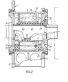
- Figure 2 is a section on the line 2-2 of Figure 1; and
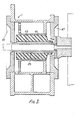
- Figure 3 is an alternative section on the line 2-2. of Figure 1.
- A horizontal continuous casting mould has a
housing structure 1 which is located in the casting position between the supply tundish for the molten metal and a run-out table for the casting, neither of which are shown. - The housing structure is mainly of fabricated metal plates and it defines a pair of
chambers cylindrical tube 6 which also defines anopening 7 through the structure, the longitudinal axis of the opening being arranged substantially horizontal. Atube 9 having an outwardly extending flange at one end is mounted within theopening 7. A number of bolts 10 secure thetube 9 to an inwardly extendingrib 13 on thetube 6 and thus form anannular enclosure 15. At each end of the structure, a group ofholes 17 are provided in thetube 6 and the group of holes at each end are in communication with therespective chambers - An annular spacer in the form of a
tube 20 is removably mounted in theopening 7 and defines anopening 23 of reduced cross-section as compared with that of theopening 7. The spacer is conveniently a push fit into the inside of thetube 9. Amould tube 25, conveniently of copper alloy, defines amould passage 27 of the cross-section of the required casting. One end of the mould tube is sealed into an aperture in anend plate 31 which is removably bolted to one end of the housing structure. The other end of the mould tube has an outwardly extendingflange 33 which is bolted to an end plate which, in turn, is removably bolted to the other end of the housing structure. - In the correct position of the mould tube, the longitudinal axis of the mould passage is coincident with the longitudinal axis of the
opening 7. - The outer surface of the mould tube is spaced apart from the
spacer 20 which surrounds it to form aduct 28 between them. - The housing structure provides cooling for the molten metal passed through the mould tube. To this end, liquid coolant, usually water, is supplied to the
chamber 3 from where it flows out through theopenings 17 atthe adjacent end of the structure into contact with the outer surface of the mould tube and the spacer. Some of the water passes along theduct 28, along the length of the outside of the mould tube and throughfurther openings 17 at the opposite end of the structure into thechamber 5, from where it flows to drain. There is, therefore, a continuous flow of cooling water in contact with the outer surface of the mould tube. In addition, some of the cooling water which is supplied to thechamber 3 passes through openings in the flange 11 and into theenclosure 15 and out from the enclosure through afurther outlet port 35. - It is most desirable that a predetermined flow of liquid coolant along the
duct 28 takes place whatever the size of the mould tube. To this end, therefore, it is necessary to keep the cross-section of theduct 28 at a predetermined value. For each mould tube, therefore, an appropriately sized annular spacer is always provided so that the two together define a duct of the predetermined cross-section. - Figure 3 shows an alternative form of the continuous casting mould in which a casting of a much smaller cross-section than that shown in Figures 1 and 2 is required. To this end. the annular spacer and the mould tube shown in Figures 1 and 2 are removed with the
end plates new spacer 41 is pushed into thetube 9 and asecond mould tube 43 is located in the opening through the housing structure and held in position bynew end plates duct 28 and into thechamber 5. It will be noticed that the cross-section of the duct in the arrangement of Figure 3 is substantially as the cross-section of the duct in the arrangements of Figures 1 and 2. - It is important that the lowest part of all the castings produced in the mould remains level with the upper surfaces of the rolls of the roller table and, to this end, the mould can be raised or lowered with respect to the roller table.
- The horizontal continuous casting mould of this invention may incorporate electro-magnetic stirring of the molten metal passed through the mould tube. In horizontal continuous casting, the solidifying casting is withdrawn from the mould tube using a push-pull cycle withdrawal pattern and this may bring about a surface defect on the produced casting, known as a cold shut crack, a witness mark or a ghost line. By causing the molten metal in the mould tube to be stirred as part of it is solidified, the surface defects referred to above can be reduced. To this end, electric coils, indicated by the broken line in Figure 2, can be positioned in the
enclosure 15. Thespacer 20 is of magnetically transparent material. When these coils are energised with alternating current, the material can be caused to give either linear or rotational stirring of the liquid core in the mould tube. Alternatively, differential stirring intensity can be applied.along the length of the horizontal mould in orderto effect the solidification rate of the skin at any point.
Claims (5)
characterised in that mould tubes (25, 43) of different cross-sections can be installed in' the housing structure (1), the spacer (20, 41) is removably mounted in the housing structure (1) and, for each size of mould tube, there is a different correspondingly sized spacer such that the cross-section of the duct (28) between the outside of the mould tube and the inside of the spacer remains substantially the same.
Priority Applications (1)
| Application Number | Priority Date | Filing Date | Title |
|---|---|---|---|
| AT85301854T ATE35923T1 (en) | 1984-03-19 | 1985-03-18 | MOLD FOR HORIZONTAL CONTINUOUS CASTING. |
Applications Claiming Priority (2)
| Application Number | Priority Date | Filing Date | Title |
|---|---|---|---|
| GB8407072 | 1984-03-19 | ||
| GB848407072A GB8407072D0 (en) | 1984-03-19 | 1984-03-19 | Horizontal continuous casting moulds |
Publications (4)
| Publication Number | Publication Date |
|---|---|
| EP0155836A2 EP0155836A2 (en) | 1985-09-25 |
| EP0155836A3 EP0155836A3 (en) | 1986-05-14 |
| EP0155836B1 true EP0155836B1 (en) | 1988-07-27 |
| EP0155836B2 EP0155836B2 (en) | 1993-01-20 |
Family
ID=10558303
Family Applications (1)
| Application Number | Title | Priority Date | Filing Date |
|---|---|---|---|
| EP85301854A Expired - Lifetime EP0155836B2 (en) | 1984-03-19 | 1985-03-18 | Horizontal continuous casting mould |
Country Status (4)
| Country | Link |
|---|---|
| EP (1) | EP0155836B2 (en) |
| AT (1) | ATE35923T1 (en) |
| DE (1) | DE3563920D1 (en) |
| GB (1) | GB8407072D0 (en) |
Families Citing this family (2)
| Publication number | Priority date | Publication date | Assignee | Title |
|---|---|---|---|---|
| US4799533A (en) * | 1986-06-20 | 1989-01-24 | Steel Casting Engineering, Ltd. | Horizontal continuous casting mold |
| US4714103A (en) * | 1986-10-10 | 1987-12-22 | Mannesmann Demag Corporation | Continuous casting mold |
Family Cites Families (3)
| Publication number | Priority date | Publication date | Assignee | Title |
|---|---|---|---|---|
| US3321008A (en) * | 1963-10-18 | 1967-05-23 | M E A Inc | Apparatus for the continuous casting of metal |
| US3730257A (en) * | 1971-06-24 | 1973-05-01 | Koppers Co Inc | Continuous casting sleeve mold |
| IT1146499B (en) * | 1981-07-30 | 1986-11-12 | Danieli Off Mecc | LINGOTTIERA WITH TUBULAR CRYSTALLIZER |
-
1984
- 1984-03-19 GB GB848407072A patent/GB8407072D0/en active Pending
-
1985
- 1985-03-18 EP EP85301854A patent/EP0155836B2/en not_active Expired - Lifetime
- 1985-03-18 AT AT85301854T patent/ATE35923T1/en not_active IP Right Cessation
- 1985-03-18 DE DE8585301854T patent/DE3563920D1/en not_active Expired
Also Published As
| Publication number | Publication date |
|---|---|
| EP0155836A3 (en) | 1986-05-14 |
| EP0155836B2 (en) | 1993-01-20 |
| ATE35923T1 (en) | 1988-08-15 |
| EP0155836A2 (en) | 1985-09-25 |
| DE3563920D1 (en) | 1988-09-01 |
| GB8407072D0 (en) | 1984-04-26 |
Similar Documents
| Publication | Publication Date | Title |
|---|---|---|
| AU655403B2 (en) | Sidewall containment of liquid metal with horizontal alternating magnetic fields | |
| US3741280A (en) | Mould for the production of metal ingots | |
| US4239078A (en) | Cooled continuous casting mould | |
| US3888300A (en) | Apparatus for the continuous casting of metals and the like under vacuum | |
| EP0117115B1 (en) | Electromagnetic stirring mold for continuously cast blooms | |
| US3527287A (en) | Continuous-casting mold assembly | |
| EP0165316B1 (en) | Electromagnetic stirring apparatus for continuous casting machine | |
| EP0155836B2 (en) | Horizontal continuous casting mould | |
| CA2284190A1 (en) | Improved continuous casting mold and method | |
| CA1277120C (en) | Vertical or bow type continuous casting machine for steel | |
| RU2249493C2 (en) | Machine for continuous horizontal casting of metal | |
| CA1174827A (en) | Electromagnetic stirring unit for continuous steel casting mould | |
| SK45298A3 (en) | Equipment for continuous or semi-continuous casting of metals | |
| EP0068320B1 (en) | Electromagnetic stirring method and device for double casting type continuous casting apparatus | |
| EP0153086B1 (en) | Induction stirrer/continuous casting mould assembly | |
| RU2152286C1 (en) | Mould for ingot casting | |
| US3667538A (en) | Cooling system for continuous casting installations | |
| GB2276574A (en) | Installation for the continuous casting of metals including an orifice plate | |
| KR0123141Y1 (en) | Molten steel surface oxidation prevention device in twin roll type sheet casting machine | |
| KR840001657Y1 (en) | Electronic stirring unit for continuous cast steel mold | |
| SU745590A1 (en) | Apparatus for crystallizing metals | |
| JPS6328701B2 (en) | ||
| CA1104787A (en) | Apparatus for continuous and semi-continuous casting of metal | |
| KR100329595B1 (en) | Separate Core for Control The Generate Magnetic Field | |
| JP3343387B2 (en) | Roll continuous casting equipment |
Legal Events
| Date | Code | Title | Description |
|---|---|---|---|
| PUAI | Public reference made under article 153(3) epc to a published international application that has entered the european phase |
Free format text: ORIGINAL CODE: 0009012 |
|
| AK | Designated contracting states |
Designated state(s): AT BE CH DE FR GB IT LI LU NL SE |
|
| PUAL | Search report despatched |
Free format text: ORIGINAL CODE: 0009013 |
|
| AK | Designated contracting states |
Kind code of ref document: A3 Designated state(s): AT BE CH DE FR GB IT LI LU NL SE |
|
| 17P | Request for examination filed |
Effective date: 19861113 |
|
| 17Q | First examination report despatched |
Effective date: 19870427 |
|
| GRAA | (expected) grant |
Free format text: ORIGINAL CODE: 0009210 |
|
| AK | Designated contracting states |
Kind code of ref document: B1 Designated state(s): AT BE CH DE FR GB IT LI LU NL SE |
|
| PG25 | Lapsed in a contracting state [announced via postgrant information from national office to epo] |
Ref country code: SE Effective date: 19880727 Ref country code: NL Effective date: 19880727 Ref country code: LI Effective date: 19880727 Ref country code: CH Effective date: 19880727 Ref country code: BE Effective date: 19880727 |
|
| REF | Corresponds to: |
Ref document number: 35923 Country of ref document: AT Date of ref document: 19880815 Kind code of ref document: T |
|
| ITF | It: translation for a ep patent filed | ||
| REF | Corresponds to: |
Ref document number: 3563920 Country of ref document: DE Date of ref document: 19880901 |
|
| ET | Fr: translation filed | ||
| REG | Reference to a national code |
Ref country code: CH Ref legal event code: PL |
|
| NLV1 | Nl: lapsed or annulled due to failure to fulfill the requirements of art. 29p and 29m of the patents act | ||
| PG25 | Lapsed in a contracting state [announced via postgrant information from national office to epo] |
Ref country code: LU Free format text: LAPSE BECAUSE OF NON-PAYMENT OF DUE FEES Effective date: 19890331 |
|
| PLBI | Opposition filed |
Free format text: ORIGINAL CODE: 0009260 |
|
| 26 | Opposition filed |
Opponent name: VOEST ALPINE INDUSTRIEANLAGEN GES.M.B.H. Effective date: 19890413 |
|
| ITTA | It: last paid annual fee | ||
| PUAH | Patent maintained in amended form |
Free format text: ORIGINAL CODE: 0009272 |
|
| STAA | Information on the status of an ep patent application or granted ep patent |
Free format text: STATUS: PATENT MAINTAINED AS AMENDED |
|
| 27A | Patent maintained in amended form |
Effective date: 19930120 |
|
| AK | Designated contracting states |
Kind code of ref document: B2 Designated state(s): AT BE CH DE FR GB IT LI LU NL SE |
|
| ET3 | Fr: translation filed ** decision concerning opposition | ||
| ITF | It: translation for a ep patent filed | ||
| PGFP | Annual fee paid to national office [announced via postgrant information from national office to epo] |
Ref country code: DE Payment date: 19980327 Year of fee payment: 14 |
|
| PGFP | Annual fee paid to national office [announced via postgrant information from national office to epo] |
Ref country code: AT Payment date: 19980330 Year of fee payment: 14 |
|
| PGFP | Annual fee paid to national office [announced via postgrant information from national office to epo] |
Ref country code: FR Payment date: 19980331 Year of fee payment: 14 |
|
| PGFP | Annual fee paid to national office [announced via postgrant information from national office to epo] |
Ref country code: GB Payment date: 19990316 Year of fee payment: 15 |
|
| PG25 | Lapsed in a contracting state [announced via postgrant information from national office to epo] |
Ref country code: AT Free format text: LAPSE BECAUSE OF NON-PAYMENT OF DUE FEES Effective date: 19990318 |
|
| PG25 | Lapsed in a contracting state [announced via postgrant information from national office to epo] |
Ref country code: FR Free format text: LAPSE BECAUSE OF NON-PAYMENT OF DUE FEES Effective date: 19991130 |
|
| REG | Reference to a national code |
Ref country code: FR Ref legal event code: ST |
|
| PG25 | Lapsed in a contracting state [announced via postgrant information from national office to epo] |
Ref country code: DE Free format text: LAPSE BECAUSE OF NON-PAYMENT OF DUE FEES Effective date: 20000101 |
|
| PG25 | Lapsed in a contracting state [announced via postgrant information from national office to epo] |
Ref country code: GB Free format text: LAPSE BECAUSE OF NON-PAYMENT OF DUE FEES Effective date: 20000318 |
|
| GBPC | Gb: european patent ceased through non-payment of renewal fee |
Effective date: 20000318 |
|
| APAH | Appeal reference modified |
Free format text: ORIGINAL CODE: EPIDOSCREFNO |