EP0155034B1 - Sound attenuating structure - Google Patents
Sound attenuating structure Download PDFInfo
- Publication number
- EP0155034B1 EP0155034B1 EP19850200228 EP85200228A EP0155034B1 EP 0155034 B1 EP0155034 B1 EP 0155034B1 EP 19850200228 EP19850200228 EP 19850200228 EP 85200228 A EP85200228 A EP 85200228A EP 0155034 B1 EP0155034 B1 EP 0155034B1
- Authority
- EP
- European Patent Office
- Prior art keywords
- sheet
- passages
- core layer
- minimum
- sound attenuating
- Prior art date
- Legal status (The legal status is an assumption and is not a legal conclusion. Google has not performed a legal analysis and makes no representation as to the accuracy of the status listed.)
- Expired
Links
- 239000012792 core layer Substances 0.000 claims description 15
- 230000007704 transition Effects 0.000 claims description 3
- 238000005259 measurement Methods 0.000 description 2
- 230000010355 oscillation Effects 0.000 description 2
- 238000010521 absorption reaction Methods 0.000 description 1
- 230000001419 dependent effect Effects 0.000 description 1
- 238000002474 experimental method Methods 0.000 description 1
- 238000000034 method Methods 0.000 description 1
- 238000001228 spectrum Methods 0.000 description 1
- 238000003466 welding Methods 0.000 description 1
Images

Classifications
-
- E—FIXED CONSTRUCTIONS
- E04—BUILDING
- E04B—GENERAL BUILDING CONSTRUCTIONS; WALLS, e.g. PARTITIONS; ROOFS; FLOORS; CEILINGS; INSULATION OR OTHER PROTECTION OF BUILDINGS
- E04B1/00—Constructions in general; Structures which are not restricted either to walls, e.g. partitions, or floors or ceilings or roofs
- E04B1/62—Insulation or other protection; Elements or use of specified material therefor
- E04B1/74—Heat, sound or noise insulation, absorption, or reflection; Other building methods affording favourable thermal or acoustical conditions, e.g. accumulating of heat within walls
- E04B1/82—Heat, sound or noise insulation, absorption, or reflection; Other building methods affording favourable thermal or acoustical conditions, e.g. accumulating of heat within walls specifically with respect to sound only
- E04B1/84—Sound-absorbing elements
- E04B1/86—Sound-absorbing elements slab-shaped
-
- B—PERFORMING OPERATIONS; TRANSPORTING
- B32—LAYERED PRODUCTS
- B32B—LAYERED PRODUCTS, i.e. PRODUCTS BUILT-UP OF STRATA OF FLAT OR NON-FLAT, e.g. CELLULAR OR HONEYCOMB, FORM
- B32B3/00—Layered products comprising a layer with external or internal discontinuities or unevennesses, or a layer of non-planar shape; Layered products comprising a layer having particular features of form
- B32B3/10—Layered products comprising a layer with external or internal discontinuities or unevennesses, or a layer of non-planar shape; Layered products comprising a layer having particular features of form characterised by a discontinuous layer, i.e. formed of separate pieces of material
- B32B3/12—Layered products comprising a layer with external or internal discontinuities or unevennesses, or a layer of non-planar shape; Layered products comprising a layer having particular features of form characterised by a discontinuous layer, i.e. formed of separate pieces of material characterised by a layer of regularly- arranged cells, e.g. a honeycomb structure
-
- E—FIXED CONSTRUCTIONS
- E04—BUILDING
- E04C—STRUCTURAL ELEMENTS; BUILDING MATERIALS
- E04C2/00—Building elements of relatively thin form for the construction of parts of buildings, e.g. sheet materials, slabs, or panels
- E04C2/30—Building elements of relatively thin form for the construction of parts of buildings, e.g. sheet materials, slabs, or panels characterised by the shape or structure
- E04C2/34—Building elements of relatively thin form for the construction of parts of buildings, e.g. sheet materials, slabs, or panels characterised by the shape or structure composed of two or more spaced sheet-like parts
- E04C2/36—Building elements of relatively thin form for the construction of parts of buildings, e.g. sheet materials, slabs, or panels characterised by the shape or structure composed of two or more spaced sheet-like parts spaced apart by transversely-placed strip material, e.g. honeycomb panels
- E04C2/365—Building elements of relatively thin form for the construction of parts of buildings, e.g. sheet materials, slabs, or panels characterised by the shape or structure composed of two or more spaced sheet-like parts spaced apart by transversely-placed strip material, e.g. honeycomb panels by honeycomb structures
-
- G—PHYSICS
- G10—MUSICAL INSTRUMENTS; ACOUSTICS
- G10K—SOUND-PRODUCING DEVICES; METHODS OR DEVICES FOR PROTECTING AGAINST, OR FOR DAMPING, NOISE OR OTHER ACOUSTIC WAVES IN GENERAL; ACOUSTICS NOT OTHERWISE PROVIDED FOR
- G10K11/00—Methods or devices for transmitting, conducting or directing sound in general; Methods or devices for protecting against, or for damping, noise or other acoustic waves in general
- G10K11/16—Methods or devices for protecting against, or for damping, noise or other acoustic waves in general
- G10K11/172—Methods or devices for protecting against, or for damping, noise or other acoustic waves in general using resonance effects
-
- E—FIXED CONSTRUCTIONS
- E04—BUILDING
- E04B—GENERAL BUILDING CONSTRUCTIONS; WALLS, e.g. PARTITIONS; ROOFS; FLOORS; CEILINGS; INSULATION OR OTHER PROTECTION OF BUILDINGS
- E04B1/00—Constructions in general; Structures which are not restricted either to walls, e.g. partitions, or floors or ceilings or roofs
- E04B1/62—Insulation or other protection; Elements or use of specified material therefor
- E04B1/74—Heat, sound or noise insulation, absorption, or reflection; Other building methods affording favourable thermal or acoustical conditions, e.g. accumulating of heat within walls
- E04B2001/742—Use of special materials; Materials having special structures or shape
- E04B2001/748—Honeycomb materials
Definitions
- the invention relates to a sound attenuating structure including a core layer comprising honeycomb shaped cells directed perpendicular to the main surface of the structure, a closed sheet at one side of said core layer and a perforated sheet at the other side of said core layer, at which side the sound waves are impinging onto the structure.
- the invention relates further to a sound attenuating structure including a combination of a number of core layers comprising cells directed perpendicular to the main surface of the structure, which core layers are mutually separated by perforated separating sheets, a closed sheet at one side of said combination and a perforated sheet at the other side of said combination at which side the sound waves are impinging onto the structure.
- Sound attenuating structures of this type are for instance described in the U.S. patents 4,291,080, 3,822,762 and 4,379,191. Sound attenuating structures of this type are for instance used a great deal in the outer casings of turboject engines of modern civil aircrafts for energy absorption of air oscillations or vibrations within a relatively small frequency band.
- the passages in said one sheet are embodied in the form of a regular pattern of round cylindrical openings with a diameter of 1 a 2 mm.
- the attenuation quality of said structure is influenced by a large number of parameters.
- an improvement in the acoustical resistance curve in relation to a structure of the above mentioned type is realised in that the passages in said outer sheet and (if present) in the separating sheets have a cross section presenting a minimum somewhere within the sheet thickness of the structure and increasing from said minimum towards both surfaces of the respective sheet.
- said minimum is located within that half of the sheet thickness which is directed to the outside of - the structure.
- the passages are significantly smaller and the pattern of passages has a much smaller pitch between the passages.
- said passages have, taken in the longitudinal direction, a symmetrical or asymmetrical double conical cross section with fluently embodied transitions as well as a number of passages per cm 2 equal to 2000 a 3000.
- Such a sheet has a porosity of 1 to 15%.
- the NLF of a structure of this type is approximately 2.
- said passages have, taken in the transversal direction, a circular or approximately circular cross section.
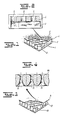
- the panel 1 of Fig. 1 has a sandwich structure including a core 2 formed by a grid of honeycomb shaped cells positioned perpendicular to the surface of the structure.
- the wall of the cells in said honeycomb grid are closed at the under side and at the upper side by the respective sheets 3 and 4.
- the lower sheet 3 is a closed sheet and the upper sheet 4 has a series of passages.
- the thickness of the sheets 3 and 4 might be different; the necessary sheet thicknesses are strongly dependent onto the mechanical strength and stiffness requirements of the complete panel.
- the sheets 3 and 4 can be attached to the core 2 by means of bonding, welding or other suitable methods.
- Fig. 2 illustrates a partial cross section especially through the upper sheet 4 with the therein provided passages 5 which, as appears clearly from Fig. 2, have in general a cylindrical shape.
- the panel according to the invention is illustrated in Fig. 3 and including a core 12, the lower sheet 13 and the upper sheet 14.
- the essential difference with the structure of Fig. 1 and 2 is formed by the number of passages, the mutual distances thereof and especially the shape of the passages in the upper sheet 14, which shape is in more detail illustrated in Fig. 4.
- the passages 15 have a varying cross section of which the diameter is minimal somewhere within the sheet thickness, preferably in that half of the sheet thickness directed to the outside of the structure, and from this minimum diameter the diameter increases fluently towards both sheet surfaces.
- the passages have, viewed in longitudinal direction, an asymmetrical diabolo shape.
- a double conical shape with a fluently embodied shape and round transitions Preferably an asymmetrical shape is used whereby the smallest diameter of the passage is positioned in that half of the sheet thickness directed to the outside (the side onto which the sound waves are impinging).
- Fig. 5 illustrates measurement results both for the panel of Fig. 1 as well as for the structure of Fig. 3.
- the air transfer speed is plotted, that means the air speed in the direction perpendicular to the structure and measured at a relatively large distance from the structure.
- the factor R/pC is plotted whereby R is the acoustical resistance, p is the average air density and C is the average sound speed.
- the curve a applies to a panel which has at the side of the passing air stream respectively at the side of the sound source cylindrical round perforations as illustrated in Fig. 1.
- the line b applies to the embodiment according to the invention illustrated in Fig. 3.
- the measurements are carried out with an upper sheet having a porosity of 4%, in other words the passages measured at their minimal diameter are covering 4% of the surface area of the sheet 14, whereby the passage density was approximately 2850 per cm 2 .
- the ultimate shape of the passages as well as the number of passages per surface area unit may depend on the particular sound situation.
- the thickness of the front sheet 14 is amongst others determined by the inner shape of the passages and by the number of passages per surface area unit, the thickness of the sheet can in correspondence with the attenuation requirements, be selected such small that between the core 12 and the sheet 14 a further sustaining sheet is necessary.
- a sustaining sheet has in general a relatively large porosity.
- the structure according to the invention respectively the panels fabricated using such a structure or shaped products thereof are marketed by applicant under the trade name Perfolin.
Landscapes
- Engineering & Computer Science (AREA)
- Physics & Mathematics (AREA)
- Architecture (AREA)
- Acoustics & Sound (AREA)
- Civil Engineering (AREA)
- Structural Engineering (AREA)
- Multimedia (AREA)
- Electromagnetism (AREA)
- Building Environments (AREA)
- Soundproofing, Sound Blocking, And Sound Damping (AREA)
Description
- The invention relates to a sound attenuating structure including a core layer comprising honeycomb shaped cells directed perpendicular to the main surface of the structure, a closed sheet at one side of said core layer and a perforated sheet at the other side of said core layer, at which side the sound waves are impinging onto the structure.
- The invention relates further to a sound attenuating structure including a combination of a number of core layers comprising cells directed perpendicular to the main surface of the structure, which core layers are mutually separated by perforated separating sheets, a closed sheet at one side of said combination and a perforated sheet at the other side of said combination at which side the sound waves are impinging onto the structure.
- Sound attenuating structures of this type are for instance described in the U.S. patents 4,291,080, 3,822,762 and 4,379,191. Sound attenuating structures of this type are for instance used a great deal in the outer casings of turboject engines of modern civil aircrafts for energy absorption of air oscillations or vibrations within a relatively small frequency band. In the known structures the passages in said one sheet are embodied in the form of a regular pattern of round cylindrical openings with a diameter of 1 a 2 mm. The attenuation quality of said structure is influenced by a large number of parameters. These parameters relate to the geometry of the combination of the (preferably honeycomb shaped) cells in the core layer or layers and the perforation openings in the separating sheets and/or in said one outer sheet, and to the contents of the frequency spectrum of air oscillations or vibrations as well as the speed of the air passing along said structure. Using such a structure into the inlet/exhaust of a turboject engine a frequency range of 500-6000 Hz and sound pressures of approximately 160 dB have to be considered as well as an air speed along this structure of for instance Mach 0.15 to 0.8.
- Experiments to the behaviour of sound attenuating panels, positioned within channels as for instance the inlet passage of turbojet aircraft engines have shown that the whole situation is very complex. An important parameter for the quality of a panel as noise attenuating panel is the acoustical resistance of said panel. Ideal is a constant value of said parameter within a predetermined range of sound pressures and air speeds along the panel. In known structures with openings of 1 a 2 mm the curve of the acoustical resistance is certainly not ideal. The so-called non-linearity factor NLF for said structure is approximately equal to 10. The NLF is the ratio between the acoustical resistances at 200 cm/sec and 20 cm/sec.
- According to the invention an improvement in the acoustical resistance curve in relation to a structure of the above mentioned type is realised in that the passages in said outer sheet and (if present) in the separating sheets have a cross section presenting a minimum somewhere within the sheet thickness of the structure and increasing from said minimum towards both surfaces of the respective sheet. In an alternative embodiment said minimum is located within that half of the sheet thickness which is directed to the outside of - the structure. Furthermore the passages are significantly smaller and the pattern of passages has a much smaller pitch between the passages. Preferably said passages have, taken in the longitudinal direction, a symmetrical or asymmetrical double conical cross section with fluently embodied transitions as well as a number of passages per cm2 equal to 2000 a 3000. Such a sheet has a porosity of 1 to 15%. The NLF of a structure of this type is approximately 2. Preferably said passages have, taken in the transversal direction, a circular or approximately circular cross section.
- The invention will now be explained in more detail with reference to the drawings.
- Fig. 1 illustrates a partly worked open perspective view of an acoustical panel known from the state of the art.
- Fig. 2 illustrates a cross section especially through the perforated sheet belonging to the panel in Fig. 1.
- Fig. 3 and 4 illustrate similar views as Fig. 1 and 2, however of an embodiment of a structure according to the invention.
- Fig. 5 illustrates graphically curves for the acoustical resistances of the panels of Fig. 1 and 3.
- The
panel 1 of Fig. 1 has a sandwich structure including acore 2 formed by a grid of honeycomb shaped cells positioned perpendicular to the surface of the structure. The wall of the cells in said honeycomb grid are closed at the under side and at the upper side by therespective sheets lower sheet 3 is a closed sheet and theupper sheet 4 has a series of passages. The thickness of thesheets sheets core 2 by means of bonding, welding or other suitable methods. - Fig. 2 illustrates a partial cross section especially through the
upper sheet 4 with the therein providedpassages 5 which, as appears clearly from Fig. 2, have in general a cylindrical shape. - The panel according to the invention is illustrated in Fig. 3 and including a
core 12, thelower sheet 13 and theupper sheet 14. The essential difference with the structure of Fig. 1 and 2 is formed by the number of passages, the mutual distances thereof and especially the shape of the passages in theupper sheet 14, which shape is in more detail illustrated in Fig. 4. Thepassages 15 have a varying cross section of which the diameter is minimal somewhere within the sheet thickness, preferably in that half of the sheet thickness directed to the outside of the structure, and from this minimum diameter the diameter increases fluently towards both sheet surfaces. In Fig. 4 the passages have, viewed in longitudinal direction, an asymmetrical diabolo shape. Within the scope of the invention however also other shapes are possible for instance a double conical shape with a fluently embodied shape and round transitions. Preferably an asymmetrical shape is used whereby the smallest diameter of the passage is positioned in that half of the sheet thickness directed to the outside (the side onto which the sound waves are impinging). - Fig. 5 illustrates measurement results both for the panel of Fig. 1 as well as for the structure of Fig. 3. Along the horizontal axis the air transfer speed is plotted, that means the air speed in the direction perpendicular to the structure and measured at a relatively large distance from the structure. Along the vertical axis the factor R/pC is plotted whereby R is the acoustical resistance, p is the average air density and C is the average sound speed. The curve a applies to a panel which has at the side of the passing air stream respectively at the side of the sound source cylindrical round perforations as illustrated in Fig. 1. The line b applies to the embodiment according to the invention illustrated in Fig. 3. The measurements are carried out with an upper sheet having a porosity of 4%, in other words the passages measured at their minimal diameter are covering 4% of the surface area of the
sheet 14, whereby the passage density was approximately 2850 per cm2. In practice the ultimate shape of the passages as well as the number of passages per surface area unit may depend on the particular sound situation. - Because the thickness of the
front sheet 14 is amongst others determined by the inner shape of the passages and by the number of passages per surface area unit, the thickness of the sheet can in correspondence with the attenuation requirements, be selected such small that between thecore 12 and the sheet 14 a further sustaining sheet is necessary. Such a sustaining sheet has in general a relatively large porosity. - The structure according to the invention respectively the panels fabricated using such a structure or shaped products thereof are marketed by applicant under the trade name Perfolin.
Claims (5)
Applications Claiming Priority (4)
| Application Number | Priority Date | Filing Date | Title |
|---|---|---|---|
| NL8400655 | 1984-02-29 | ||
| NL8400655A NL8400655A (en) | 1984-02-29 | 1984-02-29 | Sound attenuating structure with honeycomb core - has perforated facing sheet with apertures of double conical longitudinal section |
| US06/603,500 US4539245A (en) | 1984-04-24 | 1984-04-24 | Sound attenuating structure |
| US603500 | 1984-04-24 |
Publications (3)
| Publication Number | Publication Date |
|---|---|
| EP0155034A2 EP0155034A2 (en) | 1985-09-18 |
| EP0155034A3 EP0155034A3 (en) | 1987-04-15 |
| EP0155034B1 true EP0155034B1 (en) | 1988-10-12 |
Family
ID=26645931
Family Applications (1)
| Application Number | Title | Priority Date | Filing Date |
|---|---|---|---|
| EP19850200228 Expired EP0155034B1 (en) | 1984-02-29 | 1985-02-20 | Sound attenuating structure |
Country Status (2)
| Country | Link |
|---|---|
| EP (1) | EP0155034B1 (en) |
| DE (1) | DE3565568D1 (en) |
Cited By (2)
| Publication number | Priority date | Publication date | Assignee | Title |
|---|---|---|---|---|
| USD453016S1 (en) | 2000-07-20 | 2002-01-22 | B & W Loudspeakers Limited | Loudspeaker unit |
| CN107438881A (en) * | 2015-04-10 | 2017-12-05 | Mra系统有限公司 | Acoustic Linings and Methods of Constructing Acoustic Linings |
Families Citing this family (4)
| Publication number | Priority date | Publication date | Assignee | Title |
|---|---|---|---|---|
| EP0552400A1 (en) * | 1992-01-24 | 1993-07-28 | Eldim, Inc. | Sound absorbing corrugated structural material |
| US6287436B1 (en) | 1998-02-27 | 2001-09-11 | Innovent, Inc. | Brazed honeycomb collimator |
| GB2365250C (en) | 2000-07-21 | 2005-04-04 | B & W Loudspeakers | Acoustic structures |
| BE1013919A5 (en) * | 2001-01-16 | 2002-12-03 | Deceuninck N V | Sound absorbing wall element. |
Family Cites Families (4)
| Publication number | Priority date | Publication date | Assignee | Title |
|---|---|---|---|---|
| US2280631A (en) * | 1938-06-16 | 1942-04-21 | Burgess Battery Co | Facing sheet for sound absorbing material |
| AU483770B2 (en) * | 1975-01-21 | 1976-07-22 | Lockheed Aircraft Corp. | Dual range sound absorber |
| GB2056367B (en) * | 1979-07-06 | 1983-06-02 | Rohr Industries Inc | Process for producing noise attenuation panels |
| US4336292A (en) * | 1980-07-11 | 1982-06-22 | Rohr Industries, Inc. | Multi-layer honeycomb thermo-barrier material |
-
1985
- 1985-02-20 DE DE8585200228T patent/DE3565568D1/en not_active Expired
- 1985-02-20 EP EP19850200228 patent/EP0155034B1/en not_active Expired
Cited By (2)
| Publication number | Priority date | Publication date | Assignee | Title |
|---|---|---|---|---|
| USD453016S1 (en) | 2000-07-20 | 2002-01-22 | B & W Loudspeakers Limited | Loudspeaker unit |
| CN107438881A (en) * | 2015-04-10 | 2017-12-05 | Mra系统有限公司 | Acoustic Linings and Methods of Constructing Acoustic Linings |
Also Published As
| Publication number | Publication date |
|---|---|
| EP0155034A3 (en) | 1987-04-15 |
| DE3565568D1 (en) | 1988-11-17 |
| EP0155034A2 (en) | 1985-09-18 |
Similar Documents
| Publication | Publication Date | Title |
|---|---|---|
| EP0509166B1 (en) | Honeycomb noise attenuation structure | |
| US4539245A (en) | Sound attenuating structure | |
| US4539244A (en) | Honeycomb noise attenuation structure | |
| US6755280B2 (en) | Method for producing a panel comprising an adapted acoustically resistive layer and panel so obtained | |
| US4001473A (en) | Sound attenuating structural honeycomb sandwich material | |
| US4421201A (en) | High efficiency broadband acoustic resonator and absorption panel | |
| US4318453A (en) | Double layer attenuation panel | |
| US4433021A (en) | Sound attenuation sandwich panel including barrier material for corrosion control | |
| US11353240B2 (en) | Low drag, variable-depth acoustic liner | |
| US4294329A (en) | Double layer attenuation panel with two layers of linear type material | |
| US4254171A (en) | Method of manufacture of honeycomb noise attenuation structure and the resulting structure produced thereby | |
| US4850093A (en) | Method of making an acoustic attenuating liner | |
| EP2126898B1 (en) | Acoustic septum cap honeycomb | |
| US7963362B2 (en) | Acoustic panel having a variable acoustic characteristic | |
| US4421811A (en) | Method of manufacturing double layer attenuation panel with two layers of linear type material | |
| US4313524A (en) | Bulk acoustic absorber panels for use in high speed gas flow environments | |
| US4271219A (en) | Method of manufacturing an adhesive bonded acoustical attenuation structure and the resulting structure | |
| US3507355A (en) | Multi-layer face material for sound absorptive duct lining material | |
| EP3295455B1 (en) | Acoustic structures with multiple degrees of freedom | |
| US4291080A (en) | Sound attenuating structural panel | |
| AU2014307026B2 (en) | Sound wave guide for use in acoustic structures | |
| DE69817927T2 (en) | Structure with low sound induced vibration response | |
| CA2973910C (en) | Method for making contoured acoustic structures | |
| EP2026325A2 (en) | Linear acoustic liner | |
| US20020157764A1 (en) | Method for making a sound reducing panel with resistive layer having structural property and resulting panel |
Legal Events
| Date | Code | Title | Description |
|---|---|---|---|
| PUAI | Public reference made under article 153(3) epc to a published international application that has entered the european phase |
Free format text: ORIGINAL CODE: 0009012 |
|
| AK | Designated contracting states |
Designated state(s): DE FR GB |
|
| PUAL | Search report despatched |
Free format text: ORIGINAL CODE: 0009013 |
|
| AK | Designated contracting states |
Kind code of ref document: A3 Designated state(s): DE FR GB |
|
| 17P | Request for examination filed |
Effective date: 19870826 |
|
| 17Q | First examination report despatched |
Effective date: 19880217 |
|
| GRAA | (expected) grant |
Free format text: ORIGINAL CODE: 0009210 |
|
| RAP1 | Party data changed (applicant data changed or rights of an application transferred) |
Owner name: FOKKER AIRCRAFT B.V. |
|
| AK | Designated contracting states |
Kind code of ref document: B1 Designated state(s): DE FR GB |
|
| REF | Corresponds to: |
Ref document number: 3565568 Country of ref document: DE Date of ref document: 19881117 |
|
| ET | Fr: translation filed | ||
| PLBE | No opposition filed within time limit |
Free format text: ORIGINAL CODE: 0009261 |
|
| STAA | Information on the status of an ep patent application or granted ep patent |
Free format text: STATUS: NO OPPOSITION FILED WITHIN TIME LIMIT |
|
| 26N | No opposition filed | ||
| PGFP | Annual fee paid to national office [announced via postgrant information from national office to epo] |
Ref country code: GB Payment date: 19950210 Year of fee payment: 11 Ref country code: FR Payment date: 19950210 Year of fee payment: 11 |
|
| PGFP | Annual fee paid to national office [announced via postgrant information from national office to epo] |
Ref country code: DE Payment date: 19950222 Year of fee payment: 11 |
|
| PG25 | Lapsed in a contracting state [announced via postgrant information from national office to epo] |
Ref country code: GB Effective date: 19960220 |
|
| GBPC | Gb: european patent ceased through non-payment of renewal fee |
Effective date: 19960220 |
|
| PG25 | Lapsed in a contracting state [announced via postgrant information from national office to epo] |
Ref country code: FR Effective date: 19961031 |
|
| PG25 | Lapsed in a contracting state [announced via postgrant information from national office to epo] |
Ref country code: DE Effective date: 19961101 |
|
| REG | Reference to a national code |
Ref country code: FR Ref legal event code: ST |