EP0154936B1 - An exposed polycrystalline diamond mounted in a matrix body drill bit - Google Patents
An exposed polycrystalline diamond mounted in a matrix body drill bit Download PDFInfo
- Publication number
- EP0154936B1 EP0154936B1 EP85102568A EP85102568A EP0154936B1 EP 0154936 B1 EP0154936 B1 EP 0154936B1 EP 85102568 A EP85102568 A EP 85102568A EP 85102568 A EP85102568 A EP 85102568A EP 0154936 B1 EP0154936 B1 EP 0154936B1
- Authority
- EP
- European Patent Office
- Prior art keywords
- matrix
- matrix material
- bit
- diamond body
- diamond
- Prior art date
- Legal status (The legal status is an assumption and is not a legal conclusion. Google has not performed a legal analysis and makes no representation as to the accuracy of the status listed.)
- Expired
Links
Images

Classifications
-
- E—FIXED CONSTRUCTIONS
- E21—EARTH OR ROCK DRILLING; MINING
- E21B—EARTH OR ROCK DRILLING; OBTAINING OIL, GAS, WATER, SOLUBLE OR MELTABLE MATERIALS OR A SLURRY OF MINERALS FROM WELLS
- E21B10/00—Drill bits
- E21B10/46—Drill bits characterised by wear resisting parts, e.g. diamond inserts
- E21B10/56—Button-type inserts
- E21B10/567—Button-type inserts with preformed cutting elements mounted on a distinct support, e.g. polycrystalline inserts
- E21B10/5673—Button-type inserts with preformed cutting elements mounted on a distinct support, e.g. polycrystalline inserts having a non planar or non circular cutting face
-
- E—FIXED CONSTRUCTIONS
- E21—EARTH OR ROCK DRILLING; MINING
- E21B—EARTH OR ROCK DRILLING; OBTAINING OIL, GAS, WATER, SOLUBLE OR MELTABLE MATERIALS OR A SLURRY OF MINERALS FROM WELLS
- E21B10/00—Drill bits
- E21B10/46—Drill bits characterised by wear resisting parts, e.g. diamond inserts
Definitions
- the invention relates to drill bits of the kind referred to in the pre-characterizing portion of claim 1.
- the PCD products are fabricated from synthetic and/or appropriately sized natural diamond crystals under heat and pressure and in the presence of a solvent/catalyst to form the polycrystalline structure.
- the polycrystalline structures includes sintering aid material distributed essentially in the interstices where adjacent crystals have not bonded together.
- the resulting diamond sintered product is porous, porosity being achieved by dissolving out the nondiamond material or at least a portion thereof, as disclosed for example, in U.S. 3,745,623; 4,104,344 and 4,224,380.
- a material may be described as a porous PCD, as referenced in U.S. 4,224,380.
- Polycrystalline diamonds have been used in drilling products either as individual elements or as relatively thin PCD tables supported on a cemented tungsten carbide (WC) support backings.
- WC cemented tungsten carbide
- the PCD compact is supported on a cylindrical slug about 13.3 mm in diameter and about 3 mm long, with a PCD table of about 0.5 to 0.6 mm in cross section on the face of the cutter.
- the PCD table also is supported by a cylindrical substrate of tungsten carbide of about 3 mm by 13.3 mm in diameter by 26 mm in overall length.
- the natural diamond could be either surface-set in a predetermined orientation as described, for example, in U.S. Patent 3,709,308, or impregnated, i.e., diamond is distributed throughout the matrix in grit or fine and/or coarse particle form as described in U.S. Patent 3,885,637.
- thermally stable PCD elements typically porous PCD material
- PCD elements could be surface-set into the metal matrix much in the same fashion as natural diamonds, thus simplifying the manufacturing process of the drill tool, and providing better performance due to the fact that PCD elements were believed to have advantages of less tendency to polish, and lack of extended inherently weak cleavage planes as compared to natural diamond.
- porous PCD compacts and those said to be temperature stable up to about 1200°C are available in a variety of shapes, e.g., cylindrical and triangular.
- the triangular material typically is about 0.3 carats in weight, measures 4 mm on a side and is about 2.6 mm thick. It is suggested by the prior art that the triangular porous PCD compact be surface-set on the face with a minimal point exposure, i.e., less than 0.5 mm above the adjacent metal matrix face for rock drills.
- the difficulties with such placements are several.
- the difficulties may be understood by considering the dynamics of the drilling operation.
- a fluid such as water, air or drilling mud is pumped through the center of the tool, radially- outwardly across the tool face, radially around the outer surface (gage) and then back up the bore.
- the drilling fluid clears the tool face of cuttings and to some extent cools the cutter face.
- the cuttings may not be cleared from the face, especially where the formation is soft or sticky.
- the clearance between the cutting surface- formation interface and the tool body face is relatively small and if no provision is made for chip clearance, there may be bit clearing problems.
- the weight on the drill bit normally the weight of the drill string and principally the weight of the drill collar, and the effect of the fluid which tends to lift the bit off the bottom. It has been reported, for example, that the pressure beneath a diamond bit may be as much as 1000 psi greater than the pressure above the bit, resulting in a hydraulic lift, and in some cases the hydraulic lift force exceeds 50% of the applied load while drilling.
- Object of the invention is to provide a drill bit having thermally stable cutting elements cutting without a long run-in period and providing a.sufficient clearance to the formation for effective flow of drilling fluid and for clearance of cuttings.
- the present invention is an improvement in a drill bit as claimed in claim 1, and further embodiments being claimed in claims 2-6.
- the drill bit according to the invention which can be manufactured at reasonable costs and which will perform well in terms of length of bit life and rate of penetration, provides an extremely large initial exposure to accommodate expected wearing during drilling, to allow for tip removal during run-in, and to initially ensure flow clearance.
- the diamond body of a defined predetermined geometry is disposed in the matrix body of the bit to establish at least two locking regions so effectively locking the diamond body in the matrix in order to provide reasonably long life by preventing loss of PCD elements other than by normal wear.
- the drill bit is usable in specific formations without the necessity of significantly increased drill string weight, bit torque, or significant increases in drilling fluid flow or pressure, and which will drill at a higher ROP than conventional bits under the same drilling conditions.
- the manner in which the diamond body is disposed in the matrix material is dependent in part on the geometry of the diamond body.
- the diamond body is oriented in the matrix material so that at least one surface or portion of a surface of the diamond body is acutely inclined with respect to the normal to the surface of the matrix material at the location of the diamond body.
- the matrix material thus forming a wedgelike locking region over the diamond body where it is acutely inclined with respect to the normal to the matrix surface at the location of the diamond body on the bit.
- the invention is illustrated below in a plurality of geometric shapes including triangular prismatic shaped elements, prismatic rectangular elements, cylindrical elements, ovulate elements, and plate-like elements.
- the invention can be incorporated in free-form shapes which incorporate a negatively curved surface which produces a lip or pedestal extending and disposed below the surface of the matrix material or the bit face.
- the invention is the embedding and interlocking of a hard cutting element into a bit body. More particularly, the invention comprises the embedding and interlocking of a polycrystalline synthetic, diamond (PCD) element into a matrix body bit such that the diamond element is substantially exposed above the surface of the matrix.
- PCD polycrystalline synthetic, diamond
- the embodiment and interlocking of the diamond element is provided in such a way, as described in greater detail below that at least two locking points are provided between the diamond element and the matrix by virtue of the embedment and geometric configuration of the diamond element.
- the locking points provide means of interlocking the diamond element into the matrix in order to prevent movement or dislodging of the diamond matrix therefrom in substantially any direction including particularly the direction normal to the surface of the matrix.
- Figure 1 is a pictorial perspective of a matrix body drill 17.
- Bit face 17 is characterised by a gage 19, shoulder portion 21, flank 23, nose 25 and apex 27. These portions of bit face 17 are also provided with conventional junk slots 29 and collectors and waterways 31 in communication with an axial crowfoot (not showh). Between waterways and collectors 31 are lands or pads 33 in which a plurality of diamond elements 35 are disposed according to the invention.
- the surface of lands 33 is defined as the matrix surface and is generally planar in the localized area of each diamond element 35.
- Element 10 is configured as a triangular prism characterised by two opposing triangular end faces 12, only one of which is shown in Figure 2, and three adjacent rectangular sides 14, again only one of which is illustrated in Figure 2.
- Element 10 is prismatic, meaning that the shape of element 10 is generated by translating one triangular end face 12 in a parallel linear direction as defined by longitudinal axis 16.
- Such PCD elements are well known to the art and are manufactured under the trademark "GEOSET" by General Electric Company.
- element 10 is embedded in and interlocked with matrix 18 of bit 11 of Figure 1.
- PCD element 10 is raised well above surface 20 of matrix 18, typically by more than 30% of height 22 of element 10.
- element 10 may be mounted within matrix 18 and raised above the surface by more than 0.068 inch (1.73 mm).
- height 22 is 0.35 inch (5.20 mm).
- height 22 is 0.35 inch (5.20 mm).
- more than one-third of the linear dimension which is approximately perpendicular to the matrix surface is exposed.
- Element 10 is mounted and interlocked in matrix 18 by having one side 14forming a base 14a opposing the dihedral angle forming an apical ridge 24.
- Base 14a is disposed within matrix 18 below surface 20 by less than 30% of height 22, or in the case of the example of a 2103 "GEOSET" by less than 0.061 inch (1.56 mm).
- Apical ridge 24 forms the most outwardly extended portion of element 10 and element 10 can be set on face 20 of the matrix bit in any orientation as desired without departing from the scope of the invention.
- apical ridge 24 may be set lying in a direction parallel to the angular advance of element 10 as defined by the rotation of bit 11.
- apical ridge 24 may be set at right angles to the direction of advance of element 10 as defined by the rotation of the bit. This setting is then defined as a tangential setting.
- longitudinal axis 16 of element 10 is oriented generally parallel to surface 20 of matrix 18 at the point of attachment of element 10 thereto.
- triangular prismatic element 10 is locked within matrix 18 by at least two locking points 26, only one of which is illustrated in Figure 2. Locking points are embedded below surface 20 into matrix material 18. In the case of triangular prismatic element 10, locking point 26 is actually an entire surface. The second locking point is a like portion of the adjacent surface 14 (not shown in Figure 2) which two surfaces join to form the dihedral angle defining the apical edge 24 of element 10. Locking point 26 is thus in the embodiment of Figure 2 an inclined surface portion below surface 20.
- Element 10 is fabricated or molded into the matrix body bit by conventional infiltration techniques. As a result, matrix material 18 forms an innerlocking abutment against the sloped surface of locking point 26 thereby providing a wedged shaped lock on element 10.
- Matrix material 18 forms integral overlying wedges so that element 10 is locked into matrix 18 with respect to all directions. That is, a force in any direction tending to remove element 10 from surface 20 would be resisted by locking points 26.
- end surfaces 12 were perpendicular surfaces to longitudinal axis 16 and thus locking points 26 were formed only on opposing surfaces 14 below surface 20.
- end surfaces 12 may be inclined with respect to longitudinally axes 16 thereby providing two additional spaced apart locking points, which together with locking points 26, would form two orthogonal pairs of such locking points, or in the case of Figure 2 locking surface portions.
- FIG. 3 wherein the invention is illustrated in the context of a rectangular prismatic element, generally denoted by numeral 28.
- rectangular prismatic element 28 is shown as a cubic polycrystalline diamond element.
- Element 28 is disposed within matrix material 18 below surface 20 in such a manner that at least two locking points 30 and 32 are provided. Locking point 30 is formed at one corner 34 of cubic element 28 while locking point 32 is formed at the adjacent corners 36, one of which is illustrated in Figure 3.
- Element 28 is disposed within matrix 18 at an angle so that its normal axis of symmetry 38 is inclined with respect to surface 20 at the point of attachment of element 28 to the matrix bit.
- the inclination of axis 38 causes at least one of the four basal corners, in this case corner 34, to be cocked up at an angle so as to be disposed within matrix 18 at a lesser depth than at least one other corner of cubic element 28.
- the inclination of axis 38 is such that no face of cubic element 28 is perpendicular to surface 20.
- the inclination of axis 38 causes corner 34 to be the highest corner followed by adjacent corners 36 and lastly, by lowest opposing corner 40.
- the angular orientation of axis 38 thus causes edge 42, which is-adjacent to corner 34, to be inclined upwardly through surface 20 of matrix material 18 at an acute angle.
- locking point 30 at corner 34 is a surface portion in the proximity of corner 34 of adjacent sides 44 which join together to form the dihedral angle 46 and edge 42.
- locking points 30 and 32 are merged to include lower surface portion of side 44 in the proximity of and adjacent to basal edge 48 from corner 34 to adjacent corner 36.
- the embedment of cubic element 28 within matrix material 18 also provides a means of resisting any forces imparted on element 28 in a direction parallel to surface 20.
- Cubic element 28 is not locked into matrix 18 only in the direction of axis 38. Resistance to these parallel or azimuthal forces which may be applied to element 28 would also be provided if axis of. symmetry 38 were substantially perpendicular to surface 20. However, in this last case, locking point 30 would have disappeared and there would be no mechanical means, other than cohesion, micromechanical attachment or other bonding between element 28 and matrix material 18 which would retain or lock element 28 in matrix material 18.
- FIG. 4 a right circular cylindrical element, generally denoted by reference numeral 50, is illustrated.
- Cylindrical element 50 is characterised by a longitudinal axis of symmetry 52.
- Element 50 is disposed within matrix 18 below surface 20 in such a manner that axis 52 is inclined at an acute angle to surface 20.
- a locking point or more strictly speaking a plurality of locking points are formed on the lower surface of element 50 in the proximity of base 56.
- base 56 is shown as a flat circular base while the opposing end of cylindrical element 50 is illustrated as being generally domed.
- the shape of opposing end 58 can be arbitrarily chosen.
- a locking point 54 is formed on an inclined surface portion of cylindrical element below surface 20 of matrix 18.
- Matrix material 18 is molded about the embedded portion of cylindrical element 50 and thereby forms a locking wedge against the acutely inclined surface portions.
- Figure 5 shows a perspective view of a triangular prismatic element 10 which was shown and described in connection with Figure 2 disposed below surface 20 into matrix material 18 in such a manner that longitudinal axis 16 is acutely inclined with respect to the normal to surface 20 rather than being perpendicular thereto as shown in Figure 2.
- At least one corner 60 is thus defined as being the highest corner of element 10 which is embedded within matrix material 18.
- Adjacent corner 62 is disposed within matrix material 18 at a greater depth as determined by the size of element 10 and the angular orientation of longitudinal axis 16 with respect to the surface normal.
- At least one locking point 64 and, in fact, a plurality of locking points are then formed on that portion of side 14 disposed beneath surface 20.
- locking points 64 are formed on two adjacent sides 14 which join together to form the dihedral edge 24.
- Matrix material 18 is molded about surface 14 once again forming an overlying wedge which locks element 10 onto surface 20 and which resists substantially all forces which may be exerted upon element 10 which might tend to remove it from surface 20.
- ovulate element 66 is characterised by a major longitudinal axis 68 which defines a direction of preferential or maximum elongation.
- the angular orientation of major axis 68 of elements 66 is inclined sufficient with respect to the normal to surface 20 such that at least two locking points, again a surface portion defining the plurality of locking points 70, are defined below surface 20 on element 66.
- the curvature of ovulate element 66 is such that it begins to fall away from the normal to surface 20 as it approaches surface 20 from beneath.
- matrix material 18 is molded thereover and thus again forms a wedging mechanical lock to retain element 66 in matrix material 18.
- a locking resisting force exist for all directions except one, major axis 68.
- Figures 2-6 are each generally characterised by a diamond element having a longitudinal axis lying along a direction of major elongation of the element or at least in a direction of equal elongation as in the case of cubic element 28 in Figure 3.
- a right circular diamond disk generally denoted by reference numeral 72 is embedded within matrix material 18 and exposed above surface 20 according to the invention.
- 72 is characterised by an axis of symmetry 74.
- Axis 74 is again acutely aligned with respect to the normal at surface 20 so that one edge 76 is well exposed above matrix surface 20 while the diametrically opposing edge 78 is embedded within matrix material 18 below surface 20.
- At least two locking points are formed at a portion of the upper surface of disk 72 in the proximity of edge 78 and below surface 20.
- disk 72 is embedded in surface 20 of the matrix bit at an inclined angle such that the leading edge is fully exposed while the trailing edge is fully embedded with portions of the edges of disk 72 between diametric points 76 and 78 either being exposed or embedded to lesser or greater degrees depending on their proximity to diametrically opposed points 76 and 78 respectively. Therefore, disk 72 is securely locked within matrix 18 against both azimuthal forces and normal forces to surface 20.
- FIG. 8 The invention is further illustrated in the embodiment of Figure 8 wherein a right circular cylindrical element 50 as described in connection with the embodiment of Figure 4 is disposed into matrix 18 below surface 20.
- the exposed end 58 of cylinder 50 is shown as having a domed shape purely for convenience and not as a means of limiting the invention.
- the opposing end or base 56 is disposed at least partially within matrix material 18 so that at least two, and actually a plurality of locking points 82, are formed thereon.
- at least a portion of cylinder 50 is embedded deeply enough such that the diameter of a perpendicularly cross section to axis 52 is below surface 20.
- FIG. 9 wherein a triangular prismatic element, generally denoted by reference numeral 86, is disposed below surface 20 in matrix material 18 so that a plurality of locking points 88 are formed on its surface.
- Element 86 is similar to that described in connection with Figures 2 and 5, with the exception that element 86 has been elongated along longitudinal axis 90.
- the embodiment of Figure 9 should be interpreted to include element 10 of Figures 2 and 5 as well.
- triangular element 86 of Figure 8 includes at least a portion embedded below surface 20 of matrix 18. At each point on the embedded portion of side 92, the slope of side 92 falls away from the normal to surface 20 as surface 20 is approached from below.
- matrix material 18 is molded over side 92 thereby forming a wedge-shaped lock over the embedded portion of side 92 and thus, the plurality of locking points 88. Meanwhile, a substantial forward portion of element 86 is completely exposed above surface 20 of matrix 18. In fact, it is not necessary that trailing corner 94 be flush with surface 20 as illustrated in Figure 9. Instead, trailing corner 94 may be disposed well above surface 20 as well, locking points 88 remain established as long as any portion of adjacent sides 92 remain disposed below surface 20 into matrix 18.
- FIG. 10 wherein yet another embodiment is illustrated showing an elongated rectangular prismatic element, generally denoted by reference numeral 96.
- element 96 is embedded below surface 20 into matrix 18 with opposing sides 98 generally parallel to the normal to surface 20.
- one end surface 100 is substantially or fully exposed above surface 20 while the opposing end surface 102, only the edge of which is shown in Figure 10, is disposed beneath surface 20.
- matrix material 18 is disposed over at least a portion of one end of element 96 and forms a plurality of locking points 104.
- a wedged-shape extension of matrix 18 is integrally formed over submerged end 102 thus providing the mechanical locking which prevents any substantial dislodgement of element 96 from surface 20.
- element 96 has been shown as having a substantially elongated longitudinal axis 106, although it must be understood that the proportions of element 96 are arbitrarily fixed and could be chosen to include the embodiment of Figure 3, which is cubic, as well.
- Triangular element 108 is characterised by a longitudinal axis 110 in a direction normal to parallel and opposing end faces 112. The thickness of element 108 or the distance between opposing end faces 112 is smaller than the distance of the sides or height of triangular element 108 thereby resulting in a flat plate-like triangular element. According to the invention, element 108 is substantially exposed above surface 20 of matrix 18 and locked therein by a plurality of locking points 114.
- Locking points 114 are formed on a lower portion of end surface 112 which is disposed below surface 20 by virtue of the acute angular orientation of element 108 and its longitudinal axis 110 from the normal. Matrix material 18 forms an integral edge over this lower portion of element 108 thus defining and forming locking points 114.
- Element 116 includes at least two opposing parallel surfaces 118, the upper of which is shown in the view of Figure 12. Between opposing parallel surfaces 118 are four sides forming two opposing pairs, 120 and 122, at least one of which pairs 120 has a trapezoidal shape.
- side 120 is trapezoidal
- side 122 is generally rectangular as would be produced by truncating the triangular prismatic element 10 of Figure 2 along a plane parallel to base 14a.
- a plurality of locking points 124 are formed along lower edge of sides 122 in the same manner as locking points 26 are formed in the embodiment of Figure 2 with respect to element 10.
- element 116 is locked within the matrix 18 in substantially the same manner.
- FIG. 13 and 14 wherein a trapezoidal prismatic element 126 is shown as embedded in an inclined orientation in the matrix 18 and is locked therein by having portions below surface 20. More particularly, element 126 is shown in the illustrated embodiment of Figures 12 and 13 as fully trapezoidal in the sense that parallel rectangular faces 128 are connected by four adjacent trapezoidal-shaped faces formed in opposing pairs, namely surfaces 130 and 132. However, it must be expressly understood that the somewhat simpler trapezoidal element 116 of Figure 12 could be employed with appropriate modifications according to the invention in a substantially similar embodiment to that shown and described in connection with Figures 13 and 14.
- element 126 is disposed within an inclined portion 134 of matrix material 18 which portion 134 of matrix material 18 forms an inclined slope or support into which element 126 is embedded and locked.
- the embodiments of Figures 13 and 14 incorporate the concept of an inclined land on the bit face. Supported cutter or tooth structures are distinguishable and are better shown in the following incorporated applications assigned to the same assignee of the present invention:
- one end surface 132 as shown in Figures 13 and 14 is fully exposed and is generally coplanar with surface 20.
- the upper parallel rectangular side 128 is fully exposed as well.
- each of the three remaining side surfaces 130 and the opposing end surface 132 are embedded within matrix 18 below surface 20.
- On each of these embedded surfaces a plurality of locking points 136 are thus formed by the integral extension of matrix 18 over underlying sides 130 and 132.
- a plurality of locking points 136 are defined and established which will prevent the movement of element 126 not only in any azimuthal direction across surface 20, but in the vertical direction as well.
- Figure 15 illustrates a perspective view of a curvalinear, free-form synthetic diamond element generally denoted by reference numeral 138.
- Element 138 in the illustrated embodiment is shown as having an elongated body characterised by a smooth apical surface 140 and a rounded nose portion 142 which may be oriented in the direction of cutting as defined by rotation of the drill bit. From apical surface 140, the sides of element 138 sloped downwardly and are flared outwardly to form a generally flat basal surface 144 and a peripheral lip 146. The surface adjoining the sides of element 138 with lip 146 are thus characterised by a negative curvature evidenced through segment 148. Element 138 is therefore disposed within matrix 18 below surface 20 so that lip 146 is substantially or fully embedded therein, including at least a portion of the negatively curved surface 148.
- Matrix material 18 is therefore molded about and above lip 146, which forms a pedestal embedded into matrix 18.
- the remaining portion of diamond element 138 is fully exposed above matrix surface 20. Therefore, along the entire periphery of lip 146, a plurality of locking points 150 are defined and established which provide a means of mechanically locking diamond element 138 onto and below surface 20.
- many other free-form shapes other than that one which is arbitrarily chosen here to illustrate the invention in the embodiment of Figure 15 could be devised as well without departing from the teaching of the invention.
Landscapes
- Engineering & Computer Science (AREA)
- Life Sciences & Earth Sciences (AREA)
- Mining & Mineral Resources (AREA)
- Geology (AREA)
- Mechanical Engineering (AREA)
- Physics & Mathematics (AREA)
- Environmental & Geological Engineering (AREA)
- Fluid Mechanics (AREA)
- General Life Sciences & Earth Sciences (AREA)
- Geochemistry & Mineralogy (AREA)
- Chemical & Material Sciences (AREA)
- Crystallography & Structural Chemistry (AREA)
- Earth Drilling (AREA)
- Carbon And Carbon Compounds (AREA)
- Drilling Tools (AREA)
Description
- The invention relates to drill bits of the kind referred to in the pre-characterizing portion of claim 1.
- The use of diamonds in drilling products is well known. More recently synthetic diamonds both single crystal diamonds (SCD) and polycrystalline diamonds (PCD) have become commercially available from various sources and have been used in such products, with recognized advantages. For example, natural diamond bits effect drilling with a plowing action in comparison to crushing in the case of a roller cone bit, whereas synthetic diamonds tend to cut by a shearing action. In the case of rock formations, for example, it is believed that less energy is required to fail the rock in shear than in compression.
- More recently, a variety of synthetic diamond products has become available commercially some of which are available as polycrystalline products. Crystalline diamonds preferentially fractures on (111), (110) and (100) planes whereas PCD tends to be isotropic and exhibits this same cleavage but on a microscale and therefore resists catastrophic large scale cleavage failure. The result is a retained sharpness which appears to resist polishing and aids in cutting. Such products are described, for example, in U.S. Patents 3,913,280; 3,745,623; 3,816,085; 4,104,344 and 4,224,380.
- In general, the PCD products are fabricated from synthetic and/or appropriately sized natural diamond crystals under heat and pressure and in the presence of a solvent/catalyst to form the polycrystalline structure. In one form of product, the polycrystalline structures includes sintering aid material distributed essentially in the interstices where adjacent crystals have not bonded together.
- In another form, as described for example in U.S. Patents 3,745,623; 3,816,085; 3,913,280; 4,104,223 and 4,224,380 the resulting diamond sintered product is porous, porosity being achieved by dissolving out the nondiamond material or at least a portion thereof, as disclosed for example, in U.S. 3,745,623; 4,104,344 and 4,224,380. For convenience, such a material may be described as a porous PCD, as referenced in U.S. 4,224,380.
- Polycrystalline diamonds have been used in drilling products either as individual elements or as relatively thin PCD tables supported on a cemented tungsten carbide (WC) support backings.
- Such product is described, for example, in U.S. Patent 4,351,401.
- In one form, the PCD compact is supported on a cylindrical slug about 13.3 mm in diameter and about 3 mm long, with a PCD table of about 0.5 to 0.6 mm in cross section on the face of the cutter. In another version, a stud cutter, the PCD table also is supported by a cylindrical substrate of tungsten carbide of about 3 mm by 13.3 mm in diameter by 26 mm in overall length. These cylindrical PCD table faced cutters have been used in drilling 'products intended to be used in soft to medium-hard formations.
- Individual PCD elements of various geometrical shapes have been used as substitutes for natural diamonds in certain applications on drilling products. However, certain problems arose with PCD elements used as individual pieces of a given carat size or weight. In general, natural diamond, available in a wide variety of shapes and grades, was placed in predefined locations in a mold, and production of the tool was completed by various conventional techniques. The result is the formation of a metal carbide matrix which holds the diamond in place, this matrix sometimes being referred to as a crown, the latter attached to a steel blank by a metallurgical and mechanical bond formed during the process of forming the metal matrix. Natural diamond is sufficiently thermally stable to withstand the heating process in metal matrix formation.
- In this procedure above described, the natural diamond could be either surface-set in a predetermined orientation as described, for example, in U.S. Patent 3,709,308, or impregnated, i.e., diamond is distributed throughout the matrix in grit or fine and/or coarse particle form as described in U.S. Patent 3,885,637.
- With early PCD elements, problems arose in the production of drilling products because PCD elements especially PCD tables on carbide backing tended to be thermally unstable at the temperature used in the furnacing of the metal matrix bit crown, resulting in catastrophic failure of the PCD elements if the same procedures as were used with natural diamonds were used with them. It was believed that the catastrophic failure was due to thermal stress cracks from the expansion of residual metal or metal alloy used as the sintering aid in the formation of the PCD element.
- Brazing techniques were used to fix the cylindrical PCD table faced cutter into the matrix using temperature unstable PCD products. Brazing materials and procedures were used to assure that temperatures were not reached which would cause catastrophic failure of the PCD element during the manufacture of the drilling tool. The result was that sometimes the PCD components separated from the metal matrix, thus adversely affecting performance of the drilling tool.
- With the advent of thermally stable PCD elements, typically porous PCD material, it was believed that such elements could be surface-set into the metal matrix much in the same fashion as natural diamonds, thus simplifying the manufacturing process of the drill tool, and providing better performance due to the fact that PCD elements were believed to have advantages of less tendency to polish, and lack of extended inherently weak cleavage planes as compared to natural diamond.
- Significantly, the current literature relating to porous PCD compacts suggests that the element be surface-set. The porous PCD compacts, and those said to be temperature stable up to about 1200°C are available in a variety of shapes, e.g., cylindrical and triangular. The triangular material typically is about 0.3 carats in weight, measures 4 mm on a side and is about 2.6 mm thick. It is suggested by the prior art that the triangular porous PCD compact be surface-set on the face with a minimal point exposure, i.e., less than 0.5 mm above the adjacent metal matrix face for rock drills. Larger one per carat synthetic trianguJar diamonds have also become available, measuring 6 mm on a side and 3.7 mm thick, but no recommendation has been made as to the degree of exposure for such a diamond. In the case of abrasive rock, it is suggested by the prior art that the triangular element be set completely below the metal matrix. For soft nonabrasive rock, it is suggested by the prior art that the triangular element be set in a radial orientation with'the base at about the level of the metal matrix. The degree of exposure recommended thus depended on the type of rock formation to be cut.
- The difficulties with such placements are several. The difficulties may be understood by considering the dynamics of the drilling operation. In the usual drilling operation, be it mining, coring, or oil well drilling, a fluid such as water, air or drilling mud is pumped through the center of the tool, radially- outwardly across the tool face, radially around the outer surface (gage) and then back up the bore. The drilling fluid clears the tool face of cuttings and to some extent cools the cutter face. Where there is insufficient clearance between the formation cut and the bit body, the cuttings may not be cleared from the face, especially where the formation is soft or sticky. Thus, if the clearance between the cutting surface- formation interface and the tool body face is relatively small and if no provision is made for chip clearance, there may be bit clearing problems.
- Other factors to be considered are the weight on the drill bit, normally the weight of the drill string and principally the weight of the drill collar, and the effect of the fluid which tends to lift the bit off the bottom. It has been reported, for example, that the pressure beneath a diamond bit may be as much as 1000 psi greater than the pressure above the bit, resulting in a hydraulic lift, and in some cases the hydraulic lift force exceeds 50% of the applied load while drilling.
- One surprising observation made in drill bits having surface-set thermally stable PCD elements is that even after sufficient exposure of the cutting face has been achieved, by running the bit in the hole and after a fraction of the surface of the metal matrix was abraded away, the rate of penetration often decreases. Examination of the bit indicates unexpected polishing of the PCD elements. Usually ROP can be increased by adding weight to the drill string or replacing the bit. Adding weight to the drill string is generally objectionable because it increases stress and wear on the drill rig. Further, tripping or replacing the bit is expensive since the economics of drilling in normal cases are expressed in cost per foot of penetration. The cost calculation takes into account the bit cost plus the rig cost including trip time and drilling time divided by the footage drilled.
- Object of the invention is to provide a drill bit having thermally stable cutting elements cutting without a long run-in period and providing a.sufficient clearance to the formation for effective flow of drilling fluid and for clearance of cuttings.
- The present invention is an improvement in a drill bit as claimed in claim 1, and further embodiments being claimed in claims 2-6.
- The drill bit according to the invention which can be manufactured at reasonable costs and which will perform well in terms of length of bit life and rate of penetration, provides an extremely large initial exposure to accommodate expected wearing during drilling, to allow for tip removal during run-in, and to initially ensure flow clearance. The diamond body of a defined predetermined geometry is disposed in the matrix body of the bit to establish at least two locking regions so effectively locking the diamond body in the matrix in order to provide reasonably long life by preventing loss of PCD elements other than by normal wear. Further, the drill bit is usable in specific formations without the necessity of significantly increased drill string weight, bit torque, or significant increases in drilling fluid flow or pressure, and which will drill at a higher ROP than conventional bits under the same drilling conditions.
- The manner in which the diamond body is disposed in the matrix material is dependent in part on the geometry of the diamond body. Preferably, the diamond body is oriented in the matrix material so that at least one surface or portion of a surface of the diamond body is acutely inclined with respect to the normal to the surface of the matrix material at the location of the diamond body. The matrix material thus forming a wedgelike locking region over the diamond body where it is acutely inclined with respect to the normal to the matrix surface at the location of the diamond body on the bit.
- The invention is illustrated below in a plurality of geometric shapes including triangular prismatic shaped elements, prismatic rectangular elements, cylindrical elements, ovulate elements, and plate-like elements. In addition, the invention can be incorporated in free-form shapes which incorporate a negatively curved surface which produces a lip or pedestal extending and disposed below the surface of the matrix material or the bit face. By virtue of the spaced-apart locking regions which in the following description are called in a non-geometric sense as locking points, the diamond body is securely retained in the drill bit while allowing substantial exposure of the diamond body above the matrix surface of the drill bit.
- These and other advantages of the invention and its various embodiments are better understood by now considering the following Figures wherein like elements are reference by like numerals.
-
- Figure 1 is a pictorial perspective of a drill bit incorporating diamond elements raised above the face of the matrix surface.
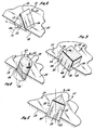
- Figure 2 is a perspective view of a triangular prismatic element embedded according to the invention within the matrix body bit of Figure 1 while allowing substantial exposure upon the surface of the bit.
- Figure 3 is a perspective view of a cubic element attached to a matrix body bit according to the invention.
- Figure 4 is a perspective view of a right circular cylinder embedded in a matrix.
- Figure 5 is a perspective view of a triangular prismatic element embedded in a generally axial orientation in the matrix body bit.
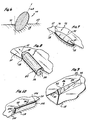
- Figure 6 is a generalized ovulate diamond body embedded in a matrix bit according to the invention.
- Figure 7 is a right circular disc embedded according to the invention in a matrix body bit.
- Figure 8 is a right circular cylindrical diamond element embedded in a generally tangential direction in a matrix body bit according to the invention.
- Figure 9 is a triangular prismatic element embedded in a generally tangential orientation.
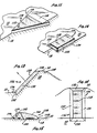
- Figure 10 is a generally rectangular prismatic element embedded in a matrix body but in a generally tangential orientation.
- Figure 11 is a triangular plate like element embedded in a matrix body bit according to the invention in a generally tangential orientation.
- Figure 12 is a trapezoidal prismatic diamond element embedded in a matrix body bit in a generally tangential orientation.
- Figure 13 is a trapezoidal prismatic element embedded in a matrix body bit in a generally axial orientation with backing or inclined support as shown in side view.
- Figure 14 is a view of the trapezoidal prismatic element shown in Figure 12.
- Figure 15 is a free form diamond body embedded in a matrix body bit according to the invention.
- The invention as exemplified in these various embodiments is better understood by now turning to the following detailed description which should be considered in light of the above drawings.
- The invention is the embedding and interlocking of a hard cutting element into a bit body. More particularly, the invention comprises the embedding and interlocking of a polycrystalline synthetic, diamond (PCD) element into a matrix body bit such that the diamond element is substantially exposed above the surface of the matrix. The embodiment and interlocking of the diamond element is provided in such a way, as described in greater detail below that at least two locking points are provided between the diamond element and the matrix by virtue of the embedment and geometric configuration of the diamond element. The locking points provide means of interlocking the diamond element into the matrix in order to prevent movement or dislodging of the diamond matrix therefrom in substantially any direction including particularly the direction normal to the surface of the matrix. The invention as it is exemplified in various embodiments can better be understood by now considering the illustrated embodiments as set forth in the figures described above.
- Figure 1 is a pictorial perspective of a matrix body drill 17. Bit face 17 is characterised by a
gage 19,shoulder portion 21,flank 23, nose 25 and apex 27. These portions of bit face 17 are also provided withconventional junk slots 29 and collectors andwaterways 31 in communication with an axial crowfoot (not showh). Between waterways andcollectors 31 are lands or pads 33 in which a plurality ofdiamond elements 35 are disposed according to the invention. The surface of lands 33 is defined as the matrix surface and is generally planar in the localized area of eachdiamond element 35. - Turn now to Figure 2 wherein a perspective view of a triangular prismatic PCD element, generally denoted by
reference numeral 10 is illustrated.Element 10 is configured as a triangular prism characterised by two opposing triangular end faces 12, only one of which is shown in Figure 2, and three adjacent rectangular sides 14, again only one of which is illustrated in Figure 2.Element 10 is prismatic, meaning that the shape ofelement 10 is generated by translating one triangular end face 12 in a parallel linear direction as defined by longitudinal axis 16. Such PCD elements are well known to the art and are manufactured under the trademark "GEOSET" by General Electric Company. - According to the invention,
element 10 is embedded in and interlocked withmatrix 18 of bit 11 of Figure 1. Contrary to the teachings of the prior art,PCD element 10 is raised well abovesurface 20 ofmatrix 18, typically by more than 30% ofheight 22 ofelement 10. For example, in the case of a 2103 "GEOSET", which is in the form of an equilateral triangular prismatic element,element 10 may be mounted withinmatrix 18 and raised above the surface by more than 0.068 inch (1.73 mm). - In such an instance,
height 22 is 0.35 inch (5.20 mm). In general, regardless of geometry, according to the invention more than one-third of the linear dimension which is approximately perpendicular to the matrix surface is exposed. -
Element 10 is mounted and interlocked inmatrix 18 by having one side 14forming a base 14a opposing the dihedral angle forming anapical ridge 24. Base 14a is disposed withinmatrix 18 belowsurface 20 by less than 30% ofheight 22, or in the case of the example of a 2103 "GEOSET" by less than 0.061 inch (1.56 mm).Apical ridge 24 forms the most outwardly extended portion ofelement 10 andelement 10 can be set onface 20 of the matrix bit in any orientation as desired without departing from the scope of the invention. For example,apical ridge 24 may be set lying in a direction parallel to the angular advance ofelement 10 as defined by the rotation of bit 11. This is termed a radial set in the case of a triangular prismatic element. Alternatively,apical ridge 24 may be set at right angles to the direction of advance ofelement 10 as defined by the rotation of the bit. This setting is then defined as a tangential setting. In both cases longitudinal axis 16 ofelement 10 is oriented generally parallel to surface 20 ofmatrix 18 at the point of attachment ofelement 10 thereto. - In any of these orientations, triangular
prismatic element 10 is locked withinmatrix 18 by at least twolocking points 26, only one of which is illustrated in Figure 2. Locking points are embedded belowsurface 20 intomatrix material 18. In the case of triangularprismatic element 10, lockingpoint 26 is actually an entire surface. The second locking point is a like portion of the adjacent surface 14 (not shown in Figure 2) which two surfaces join to form the dihedral angle defining theapical edge 24 ofelement 10. Lockingpoint 26 is thus in the embodiment of Figure 2 an inclined surface portion belowsurface 20.Element 10 is fabricated or molded into the matrix body bit by conventional infiltration techniques. As a result,matrix material 18 forms an innerlocking abutment against the sloped surface of lockingpoint 26 thereby providing a wedged shaped lock onelement 10. In other words, the embedded portions of surfaces 14 are inclined away from the normal to surface 20 and are spaced apart.Matrix material 18 forms integral overlying wedges so thatelement 10 is locked intomatrix 18 with respect to all directions. That is, a force in any direction tending to removeelement 10 fromsurface 20 would be resisted by lockingpoints 26. - In the embodiment of Figure 2, it was assumed that end surfaces 12 were perpendicular surfaces to longitudinal axis 16 and thus locking
points 26 were formed only on opposing surfaces 14 belowsurface 20. However, it is entirely within the scope of the invention that end surfaces 12 may be inclined with respect to longitudinally axes 16 thereby providing two additional spaced apart locking points, which together with lockingpoints 26, would form two orthogonal pairs of such locking points, or in the case of Figure 2 locking surface portions. - Turn now to Figure 3 wherein the invention is illustrated in the context of a rectangular prismatic element, generally denoted by
numeral 28. For convenience, rectangularprismatic element 28 is shown as a cubic polycrystalline diamond element.Element 28 is disposed withinmatrix material 18 belowsurface 20 in such a manner that at least twolocking points point 30 is formed at onecorner 34 ofcubic element 28 while lockingpoint 32 is formed at theadjacent corners 36, one of which is illustrated in Figure 3.Element 28 is disposed withinmatrix 18 at an angle so that its normal axis ofsymmetry 38 is inclined with respect to surface 20 at the point of attachment ofelement 28 to the matrix bit. The inclination ofaxis 38 causes at least one of the four basal corners, in thiscase corner 34, to be cocked up at an angle so as to be disposed withinmatrix 18 at a lesser depth than at least one other corner ofcubic element 28. In the most general case, the inclination ofaxis 38 is such that no face ofcubic element 28 is perpendicular to surface 20. In the illustrated embodiment of Figure 3, the inclination ofaxis 38 causescorner 34 to be the highest corner followed byadjacent corners 36 and lastly, by lowest opposingcorner 40. The angular orientation ofaxis 38 thus causesedge 42, which is-adjacent to corner 34, to be inclined upwardly throughsurface 20 ofmatrix material 18 at an acute angle. Thus,matrix material 18 fills aroundcorner 34 forming an overlying wedged mass which lockscorner 34 into the matrix of a bit and prevents movement ofelement 28 in a normal direction at the point of attachment. Thus, in the embodiment of Figure 3, lockingpoint 30 atcorner 34 is a surface portion in the proximity ofcorner 34 of adjacent sides 44 which join together to form the dihedral angle 46 andedge 42. In fact, lockingpoints basal edge 48 fromcorner 34 toadjacent corner 36. In other words, ifcube 28 were to be lifted in a perpendicular direction fromsurface 20,matrix material 18 in contact with lockingpoint 30 betweencorners adjacent edge 48 and the adjacent symmetrically placed edge (not shown), provide a locking surface which tends to retaincubic element 28 withinmatrix material 18. - Clearly, the embedment of
cubic element 28 withinmatrix material 18 also provides a means of resisting any forces imparted onelement 28 in a direction parallel to surface 20.Cubic element 28 is not locked intomatrix 18 only in the direction ofaxis 38. Resistance to these parallel or azimuthal forces which may be applied toelement 28 would also be provided if axis of.symmetry 38 were substantially perpendicular to surface 20. However, in this last case, lockingpoint 30 would have disappeared and there would be no mechanical means, other than cohesion, micromechanical attachment or other bonding betweenelement 28 andmatrix material 18 which would retain or lockelement 28 inmatrix material 18. - Turn now to Figure 4 wherein yet another embodiment of the invention is illustrated. In the embodiment of Figure 4 a right circular cylindrical element, generally denoted by
reference numeral 50, is illustrated.Cylindrical element 50 is characterised by a longitudinal axis ofsymmetry 52.Element 50 is disposed withinmatrix 18 belowsurface 20 in such a manner thataxis 52 is inclined at an acute angle to surface 20. By virtue of the angular orientation ofcylindrical element 50, a locking point or more strictly speaking, a plurality of locking points are formed on the lower surface ofelement 50 in the proximity ofbase 56. For convenience of illustration,base 56 is shown as a flat circular base while the opposing end ofcylindrical element 50 is illustrated as being generally domed. Clearly, the shape of opposingend 58 can be arbitrarily chosen. - Because of the angular orientation of
cylindrical element 50, alocking point 54 is formed on an inclined surface portion of cylindrical element belowsurface 20 ofmatrix 18.Matrix material 18 is molded about the embedded portion ofcylindrical element 50 and thereby forms a locking wedge against the acutely inclined surface portions. Thereby, by virtue of this embedment, both azimuthal forces parallel thesurface 20 and normal forces perpendicular to surface 20, are positively resisted by a mechanical lock ofelement 50 withinmatrix material 18. - Turn now to Figure 5 wherein yet another embodiment is illustrated. Figure 5 shows a perspective view of a triangular
prismatic element 10 which was shown and described in connection with Figure 2 disposed belowsurface 20 intomatrix material 18 in such a manner that longitudinal axis 16 is acutely inclined with respect to the normal to surface 20 rather than being perpendicular thereto as shown in Figure 2. At least one corner 60 is thus defined as being the highest corner ofelement 10 which is embedded withinmatrix material 18.Adjacent corner 62 is disposed withinmatrix material 18 at a greater depth as determined by the size ofelement 10 and the angular orientation of longitudinal axis 16 with respect to the surface normal. At least onelocking point 64 and, in fact, a plurality of locking points are then formed on that portion of side 14 disposed beneathsurface 20. In the case of the embodiment of Figure 5, locking points 64 are formed on two adjacent sides 14 which join together to form thedihedral edge 24.Matrix material 18 is molded about surface 14 once again forming an overlying wedge which lockselement 10 ontosurface 20 and which resists substantially all forces which may be exerted uponelement 10 which might tend to remove it fromsurface 20. - Whereas the embodiments of Figures 1-5 were triangular, cubical or cylindrical, the embodiment of Figure 6 has been generalized to include an arbitrary ovulate diamond element, generally denoted by
reference numeral 66. In the illustrated embodiment, ovulateelement 66 is characterised by a major longitudinal axis 68 which defines a direction of preferential or maximum elongation. The angular orientation of major axis 68 ofelements 66 is inclined sufficient with respect to the normal to surface 20 such that at least two locking points, again a surface portion defining the plurality of lockingpoints 70, are defined belowsurface 20 onelement 66. The curvature ofovulate element 66 is such that it begins to fall away from the normal to surface 20 as it approachessurface 20 from beneath. In order words,matrix material 18 is molded thereover and thus again forms a wedging mechanical lock to retainelement 66 inmatrix material 18. A locking resisting force exist for all directions except one, major axis 68. - The embodiments of Figures 2-6 described above are each generally characterised by a diamond element having a longitudinal axis lying along a direction of major elongation of the element or at least in a direction of equal elongation as in the case of
cubic element 28 in Figure 3. Turn now to Figure 7 wherein a right circular diamond disk, generally denoted byreference numeral 72 is embedded withinmatrix material 18 and exposed abovesurface 20 according to the invention. In the illustratedembodiment 72 is characterised by an axis of symmetry 74. Axis 74 is again acutely aligned with respect to the normal atsurface 20 so that oneedge 76 is well exposed abovematrix surface 20 while the diametrically opposing edge 78 is embedded withinmatrix material 18 belowsurface 20. At least two locking points, again a plurality of locking points 80, are formed at a portion of the upper surface ofdisk 72 in the proximity of edge 78 and belowsurface 20. In other words,disk 72 is embedded insurface 20 of the matrix bit at an inclined angle such that the leading edge is fully exposed while the trailing edge is fully embedded with portions of the edges ofdisk 72 betweendiametric points 76 and 78 either being exposed or embedded to lesser or greater degrees depending on their proximity to diametricallyopposed points 76 and 78 respectively. Therefore,disk 72 is securely locked withinmatrix 18 against both azimuthal forces and normal forces to surface 20. - The invention is further illustrated in the embodiment of Figure 8 wherein a right circular
cylindrical element 50 as described in connection with the embodiment of Figure 4 is disposed intomatrix 18 belowsurface 20. Again, the exposedend 58 ofcylinder 50 is shown as having a domed shape purely for convenience and not as a means of limiting the invention. The opposing end orbase 56 is disposed at least partially withinmatrix material 18 so that at least two, and actually a plurality of lockingpoints 82, are formed thereon. In other words, at least a portion ofcylinder 50 is embedded deeply enough such that the diameter of a perpendicularly cross section toaxis 52 is belowsurface 20. Even in the case wherein a portion ofbase 56 may be exposed abovesurface 20, a plurality of lockingpoints 82 are formed on that portion abovecenterline point 84 ofbase 56 which is disposed belowsurface 20. The surface ofcylindrical element 50 falls away at an acute angle from the normal to surface 20 ofmatrix material 18 assurface 20 is approached. Thus,matrix material 18 is molded over the locking points 82 oncylindrical surface 50 and forms a locking wedge thereby retainingelement 50 withinmatrix material 18. - The invention is illustrated still further in the embodiment of Figure 9. Turn now to Figure 9 wherein a triangular prismatic element, generally denoted by
reference numeral 86, is disposed belowsurface 20 inmatrix material 18 so that a plurality of lockingpoints 88 are formed on its surface.Element 86 is similar to that described in connection with Figures 2 and 5, with the exception thatelement 86 has been elongated along longitudinal axis 90. However, the embodiment of Figure 9 should be interpreted to includeelement 10 of Figures 2 and 5 as well. Like the cylindrical embodiment of Figure 7,triangular element 86 of Figure 8 includes at least a portion embedded belowsurface 20 ofmatrix 18. At each point on the embedded portion ofside 92, the slope ofside 92 falls away from the normal to surface 20 assurface 20 is approached from below. Again,matrix material 18 is molded overside 92 thereby forming a wedge-shaped lock over the embedded portion ofside 92 and thus, the plurality of locking points 88. Meanwhile, a substantial forward portion ofelement 86 is completely exposed abovesurface 20 ofmatrix 18. In fact, it is not necessary that trailing corner 94 be flush withsurface 20 as illustrated in Figure 9. Instead, trailing corner 94 may be disposed well abovesurface 20 as well, locking points 88 remain established as long as any portion ofadjacent sides 92 remain disposed belowsurface 20 intomatrix 18. - Turn now to Figure 10 wherein yet another embodiment is illustrated showing an elongated rectangular prismatic element, generally denoted by reference numeral 96. In the illustrated embodiment of Figure 9, element 96 is embedded below
surface 20 intomatrix 18 with opposingsides 98 generally parallel to the normal tosurface 20. However, oneend surface 100 is substantially or fully exposed abovesurface 20 while the opposingend surface 102, only the edge of which is shown in Figure 10, is disposed beneathsurface 20. Thus,matrix material 18 is disposed over at least a portion of one end of element 96 and forms a plurality of locking points 104. A wedged-shape extension ofmatrix 18 is integrally formed oversubmerged end 102 thus providing the mechanical locking which prevents any substantial dislodgement of element 96 fromsurface 20. Again, element 96 has been shown as having a substantially elongated longitudinal axis 106, although it must be understood that the proportions of element 96 are arbitrarily fixed and could be chosen to include the embodiment of Figure 3, which is cubic, as well. - The invention continues to be illustrated in the embodiment of Figure 11 wherein a flat triangular element, generally denoted by
reference numeral 108, is shown in perspective view disposed withinmatrix 18.Triangular element 108 is characterised by alongitudinal axis 110 in a direction normal to parallel and opposing end faces 112. The thickness ofelement 108 or the distance between opposing end faces 112 is smaller than the distance of the sides or height oftriangular element 108 thereby resulting in a flat plate-like triangular element. According to the invention,element 108 is substantially exposed abovesurface 20 ofmatrix 18 and locked therein by a plurality of locking points 114. Lockingpoints 114 are formed on a lower portion ofend surface 112 which is disposed belowsurface 20 by virtue of the acute angular orientation ofelement 108 and itslongitudinal axis 110 from the normal.Matrix material 18 forms an integral edge over this lower portion ofelement 108 thus defining and forming locking points 114. - Turn now to the embodiment of Figure 12 wherein a trapezoidal prismatic element, generally denoted by
reference numeral 116, is shown in perspective view as embedded belowsurface 20.Element 116 includes at least two opposingparallel surfaces 118, the upper of which is shown in the view of Figure 12. Between opposingparallel surfaces 118 are four sides forming two opposing pairs, 120 and 122, at least one of which pairs 120 has a trapezoidal shape. In the illustrated embodiment of Figure 2,side 120, is trapezoidal, whileside 122 is generally rectangular as would be produced by truncating the triangularprismatic element 10 of Figure 2 along a plane parallel to base 14a. Therefore, in the embodiment of Figure 12 a plurality of locking points 124 are formed along lower edge ofsides 122 in the same manner as lockingpoints 26 are formed in the embodiment of Figure 2 with respect toelement 10. Thus,element 116 is locked within thematrix 18 in substantially the same manner. - Turn now, however, to the embodiment of the invention as illustrated in Figures 13 and 14 wherein a trapezoidal
prismatic element 126 is shown as embedded in an inclined orientation in thematrix 18 and is locked therein by having portions belowsurface 20. More particularly,element 126 is shown in the illustrated embodiment of Figures 12 and 13 as fully trapezoidal in the sense that parallelrectangular faces 128 are connected by four adjacent trapezoidal-shaped faces formed in opposing pairs, namely surfaces 130 and 132. However, it must be expressly understood that the somewhat simplertrapezoidal element 116 of Figure 12 could be employed with appropriate modifications according to the invention in a substantially similar embodiment to that shown and described in connection with Figures 13 and 14. - With continued reference to Figures 13 and 14,
element 126 is disposed within an inclined portion 134 ofmatrix material 18 which portion 134 ofmatrix material 18 forms an inclined slope or support into whichelement 126 is embedded and locked. The embodiments of Figures 13 and 14 incorporate the concept of an inclined land on the bit face. Supported cutter or tooth structures are distinguishable and are better shown in the following incorporated applications assigned to the same assignee of the present invention:
- In the illustrated embodiment, one
end surface 132 as shown in Figures 13 and 14 is fully exposed and is generally coplanar withsurface 20. In addition thereto, the upper parallelrectangular side 128 is fully exposed as well. However, each of the three remaining side surfaces 130 and the opposingend surface 132 are embedded withinmatrix 18 belowsurface 20. On each of these embedded surfaces a plurality of lockingpoints 136 are thus formed by the integral extension ofmatrix 18 overunderlying sides sides 130 and possibly along opposinglower side 132 depending upon the angular orientation ofelement 126 with respect to the local surface normal, a plurality of lockingpoints 136 are defined and established which will prevent the movement ofelement 126 not only in any azimuthal direction acrosssurface 20, but in the vertical direction as well. - The embodiments thus described in connection with Figures 1-14 have been described in each case in connection with a regular geometric shape. Clearly, the invention could be employed with many other geometric shapes other than those shown and described according to the teachings set forth. For example, in addition to regular geometric shapes, specialized or free-form shapes can also be beneficially exploited to expose a diamond cutting element above a matrix face. Turn now to Figure 15 for one such embodiment. Figure 15 illustrates a perspective view of a curvalinear, free-form synthetic diamond element generally denoted by
reference numeral 138.Element 138 in the illustrated embodiment is shown as having an elongated body characterised by a smoothapical surface 140 and a rounded nose portion 142 which may be oriented in the direction of cutting as defined by rotation of the drill bit. Fromapical surface 140, the sides ofelement 138 sloped downwardly and are flared outwardly to form a generally flat basal surface 144 and aperipheral lip 146. The surface adjoining the sides ofelement 138 withlip 146 are thus characterised by a negative curvature evidenced throughsegment 148.Element 138 is therefore disposed withinmatrix 18 belowsurface 20 so thatlip 146 is substantially or fully embedded therein, including at least a portion of the negativelycurved surface 148.Matrix material 18 is therefore molded about and abovelip 146, which forms a pedestal embedded intomatrix 18. The remaining portion ofdiamond element 138 is fully exposed abovematrix surface 20. Therefore, along the entire periphery oflip 146, a plurality of locking points 150 are defined and established which provide a means of mechanically lockingdiamond element 138 onto and belowsurface 20. Clearly, many other free-form shapes other than that one which is arbitrarily chosen here to illustrate the invention in the embodiment of Figure 15 could be devised as well without departing from the teaching of the invention. - Many modifications and alterations may be made by those having ordinary skill in the art without departing from the teachings of the invention as set forth herein. The illustrated embodiments have been chosen only as a means of example and should not be taken as limiting the scope of the invention which is defined in the following claims.
Claims (6)
Applications Claiming Priority (2)
| Application Number | Priority Date | Filing Date | Title |
|---|---|---|---|
| US59036684A | 1984-03-16 | 1984-03-16 | |
| US590366 | 1984-03-16 |
Publications (3)
| Publication Number | Publication Date |
|---|---|
| EP0154936A2 EP0154936A2 (en) | 1985-09-18 |
| EP0154936A3 EP0154936A3 (en) | 1986-06-11 |
| EP0154936B1 true EP0154936B1 (en) | 1990-05-09 |
Family
ID=24361960
Family Applications (1)
| Application Number | Title | Priority Date | Filing Date |
|---|---|---|---|
| EP85102568A Expired EP0154936B1 (en) | 1984-03-16 | 1985-03-07 | An exposed polycrystalline diamond mounted in a matrix body drill bit |
Country Status (5)
| Country | Link |
|---|---|
| EP (1) | EP0154936B1 (en) |
| JP (1) | JPS60212588A (en) |
| CA (1) | CA1248939A (en) |
| DE (1) | DE3577586D1 (en) |
| NO (1) | NO167224C (en) |
Cited By (2)
| Publication number | Priority date | Publication date | Assignee | Title |
|---|---|---|---|---|
| US9056799B2 (en) | 2010-11-24 | 2015-06-16 | Kennametal Inc. | Matrix powder system and composite materials and articles made therefrom |
| US10508503B2 (en) | 2016-09-23 | 2019-12-17 | Baker Hughes, A Ge Company, Llc | Cutting elements, earth-boring tools including the cutting elements, and methods of forming the earth-boring tools |
Families Citing this family (13)
| Publication number | Priority date | Publication date | Assignee | Title |
|---|---|---|---|---|
| ZA864402B (en) * | 1985-06-18 | 1987-02-25 | De Beers Ind Diamond | Abrasive tool |
| US4673044A (en) * | 1985-08-02 | 1987-06-16 | Eastman Christensen Co. | Earth boring bit for soft to hard formations |
| GB2188354B (en) * | 1986-03-27 | 1989-11-22 | Shell Int Research | Rotary drill bit |
| GB8907618D0 (en) * | 1989-04-05 | 1989-05-17 | Morrison Pumps Sa | Drilling |
| GB2234542B (en) * | 1989-08-04 | 1993-03-31 | Reed Tool Co | Improvements in or relating to cutting elements for rotary drill bits |
| GB9103828D0 (en) * | 1991-02-23 | 1991-04-10 | Brit Bit Limited | Improvements relating to drill bits |
| EP0996809A2 (en) * | 1997-07-15 | 2000-05-03 | Kennametal Inc. | Rotatable cutting bit assembly with cutting inserts |
| US6109377A (en) * | 1997-07-15 | 2000-08-29 | Kennametal Inc. | Rotatable cutting bit assembly with cutting inserts |
| US6176332B1 (en) | 1998-12-31 | 2001-01-23 | Kennametal Inc. | Rotatable cutting bit assembly with cutting inserts |
| DE10236483A1 (en) * | 2002-08-08 | 2004-02-19 | Hilti Ag | Hard material insert with polycrystalline diamond layer |
| US20140182947A1 (en) | 2012-12-28 | 2014-07-03 | Smith International, Inc. | Cutting insert for percussion drill bit |
| WO2017123562A1 (en) | 2016-01-13 | 2017-07-20 | Schlumberger Technology Corporation | Angled chisel insert |
| AU2024282603A1 (en) * | 2023-05-30 | 2025-12-18 | Ulterra Drilling Technologies, L.P. | Drill bits and other downhole drilling tools with non-cylindrical cutter pockets |
Family Cites Families (4)
| Publication number | Priority date | Publication date | Assignee | Title |
|---|---|---|---|---|
| US3709308A (en) * | 1970-12-02 | 1973-01-09 | Christensen Diamond Prod Co | Diamond drill bits |
| SU483863A1 (en) * | 1973-01-03 | 1980-06-15 | Всесоюзный Научно-Исследоваельский И Проектный Институт Тугоплавких Металлов И Твердых Сплавов | Method of making diamond tool |
| JPS5382601A (en) * | 1976-12-28 | 1978-07-21 | Tokiwa Kogyo Kk | Rotary grinding type excavation drill head |
| US4234048A (en) * | 1978-06-12 | 1980-11-18 | Christensen, Inc. | Drill bits embodying impregnated segments |
-
1985
- 1985-03-04 CA CA000475707A patent/CA1248939A/en not_active Expired
- 1985-03-07 EP EP85102568A patent/EP0154936B1/en not_active Expired
- 1985-03-07 DE DE8585102568T patent/DE3577586D1/en not_active Expired - Lifetime
- 1985-03-14 NO NO851019A patent/NO167224C/en unknown
- 1985-03-15 JP JP60050665A patent/JPS60212588A/en active Pending
Cited By (2)
| Publication number | Priority date | Publication date | Assignee | Title |
|---|---|---|---|---|
| US9056799B2 (en) | 2010-11-24 | 2015-06-16 | Kennametal Inc. | Matrix powder system and composite materials and articles made therefrom |
| US10508503B2 (en) | 2016-09-23 | 2019-12-17 | Baker Hughes, A Ge Company, Llc | Cutting elements, earth-boring tools including the cutting elements, and methods of forming the earth-boring tools |
Also Published As
| Publication number | Publication date |
|---|---|
| NO167224C (en) | 1991-10-16 |
| NO167224B (en) | 1991-07-08 |
| NO851019L (en) | 1985-09-17 |
| DE3577586D1 (en) | 1990-06-13 |
| EP0154936A2 (en) | 1985-09-18 |
| JPS60212588A (en) | 1985-10-24 |
| CA1248939A (en) | 1989-01-17 |
| EP0154936A3 (en) | 1986-06-11 |
Similar Documents
| Publication | Publication Date | Title |
|---|---|---|
| US4499959A (en) | Tooth configuration for an earth boring bit | |
| EP0127077B1 (en) | A rotatable drill bit | |
| US4512426A (en) | Rotating bits including a plurality of types of preferential cutting elements | |
| US4673044A (en) | Earth boring bit for soft to hard formations | |
| US4529047A (en) | Cutting tooth and a rotating bit having a fully exposed polycrystalline diamond element | |
| US6401844B1 (en) | Cutter with complex superabrasive geometry and drill bits so equipped | |
| US6000483A (en) | Superabrasive cutting element with enhanced durability and increased wear life, and apparatus so equipped | |
| US5881830A (en) | Superabrasive drill bit cutting element with buttress-supported planar chamfer | |
| CA1248939A (en) | Exposed polycrystalline diamond mounted in a matrix body drill bit | |
| US4491188A (en) | Diamond cutting element in a rotating bit | |
| EP0658682B1 (en) | Gage cutting insert for roller bit | |
| US8567534B2 (en) | Thermally stable polycrystalline diamond cutting elements and bits incorporating the same | |
| EP0117552A2 (en) | An improved diamond rotating bit | |
| US4515226A (en) | Tooth design to avoid shearing stresses | |
| EP0291314A2 (en) | Cutting structure and rotary drill bit comprising such a structure | |
| CA1218355A (en) | Tooth design using cylindrical diamond cutting elements | |
| EP0350045B1 (en) | Drill bit with composite cutting members | |
| EP0370199A1 (en) | Drill bits utilizing polycrystalline diamond grit | |
| CN114763734B (en) | Cutting elements and drill bits | |
| CA1256856A (en) | Earth boring bit for soft to hard formations | |
| JPS6332955B2 (en) |
Legal Events
| Date | Code | Title | Description |
|---|---|---|---|
| PUAI | Public reference made under article 153(3) epc to a published international application that has entered the european phase |
Free format text: ORIGINAL CODE: 0009012 |
|
| AK | Designated contracting states |
Designated state(s): BE DE FR GB |
|
| PUAL | Search report despatched |
Free format text: ORIGINAL CODE: 0009013 |
|
| AK | Designated contracting states |
Kind code of ref document: A3 Designated state(s): BE DE FR GB |
|
| 17P | Request for examination filed |
Effective date: 19861204 |
|
| 17Q | First examination report despatched |
Effective date: 19880209 |
|
| RAP1 | Party data changed (applicant data changed or rights of an application transferred) |
Owner name: EASTMAN CHRISTENSEN COMPANY |
|
| GRAA | (expected) grant |
Free format text: ORIGINAL CODE: 0009210 |
|
| AK | Designated contracting states |
Kind code of ref document: B1 Designated state(s): BE DE FR GB |
|
| REF | Corresponds to: |
Ref document number: 3577586 Country of ref document: DE Date of ref document: 19900613 |
|
| ET | Fr: translation filed | ||
| PGFP | Annual fee paid to national office [announced via postgrant information from national office to epo] |
Ref country code: GB Payment date: 19910215 Year of fee payment: 7 |
|
| PLBE | No opposition filed within time limit |
Free format text: ORIGINAL CODE: 0009261 |
|
| STAA | Information on the status of an ep patent application or granted ep patent |
Free format text: STATUS: NO OPPOSITION FILED WITHIN TIME LIMIT |
|
| PGFP | Annual fee paid to national office [announced via postgrant information from national office to epo] |
Ref country code: FR Payment date: 19910321 Year of fee payment: 7 |
|
| PGFP | Annual fee paid to national office [announced via postgrant information from national office to epo] |
Ref country code: DE Payment date: 19910327 Year of fee payment: 7 |
|
| 26N | No opposition filed | ||
| PGFP | Annual fee paid to national office [announced via postgrant information from national office to epo] |
Ref country code: BE Payment date: 19910626 Year of fee payment: 7 |
|
| PG25 | Lapsed in a contracting state [announced via postgrant information from national office to epo] |
Ref country code: GB Effective date: 19920307 |
|
| PG25 | Lapsed in a contracting state [announced via postgrant information from national office to epo] |
Ref country code: BE Effective date: 19920331 |
|
| BERE | Be: lapsed |
Owner name: EASTMAN CHRISTENSEN CY Effective date: 19920331 |
|
| GBPC | Gb: european patent ceased through non-payment of renewal fee | ||
| PG25 | Lapsed in a contracting state [announced via postgrant information from national office to epo] |
Ref country code: FR Effective date: 19921130 |
|
| PG25 | Lapsed in a contracting state [announced via postgrant information from national office to epo] |
Ref country code: DE Effective date: 19921201 |
|
| REG | Reference to a national code |
Ref country code: FR Ref legal event code: ST |