EP0154459B1 - Vehicle speed control device - Google Patents
Vehicle speed control device Download PDFInfo
- Publication number
- EP0154459B1 EP0154459B1 EP85301191A EP85301191A EP0154459B1 EP 0154459 B1 EP0154459 B1 EP 0154459B1 EP 85301191 A EP85301191 A EP 85301191A EP 85301191 A EP85301191 A EP 85301191A EP 0154459 B1 EP0154459 B1 EP 0154459B1
- Authority
- EP
- European Patent Office
- Prior art keywords
- speed
- vehicle speed
- vehicle
- control
- microprocessor
- Prior art date
- Legal status (The legal status is an assumption and is not a legal conclusion. Google has not performed a legal analysis and makes no representation as to the accuracy of the status listed.)
- Expired - Lifetime
Links
- 230000006870 function Effects 0.000 claims description 28
- 230000001133 acceleration Effects 0.000 claims description 26
- 230000004044 response Effects 0.000 claims description 15
- 230000009467 reduction Effects 0.000 claims description 6
- 230000001603 reducing effect Effects 0.000 claims description 5
- 238000006073 displacement reaction Methods 0.000 claims description 4
- 238000012937 correction Methods 0.000 abstract description 4
- 230000007246 mechanism Effects 0.000 description 11
- 239000000446 fuel Substances 0.000 description 9
- 230000001105 regulatory effect Effects 0.000 description 9
- 238000010586 diagram Methods 0.000 description 8
- 238000013459 approach Methods 0.000 description 6
- 230000001276 controlling effect Effects 0.000 description 6
- 238000012360 testing method Methods 0.000 description 6
- 230000000694 effects Effects 0.000 description 5
- 238000012544 monitoring process Methods 0.000 description 5
- 230000005540 biological transmission Effects 0.000 description 3
- 230000001143 conditioned effect Effects 0.000 description 3
- 238000000034 method Methods 0.000 description 3
- 230000008901 benefit Effects 0.000 description 2
- 230000003750 conditioning effect Effects 0.000 description 2
- 238000010276 construction Methods 0.000 description 2
- 230000009977 dual effect Effects 0.000 description 2
- 238000007667 floating Methods 0.000 description 2
- 230000010355 oscillation Effects 0.000 description 2
- 230000009471 action Effects 0.000 description 1
- 239000003990 capacitor Substances 0.000 description 1
- 230000008859 change Effects 0.000 description 1
- 238000006243 chemical reaction Methods 0.000 description 1
- 230000000994 depressogenic effect Effects 0.000 description 1
- 230000004069 differentiation Effects 0.000 description 1
- 230000036039 immunity Effects 0.000 description 1
- 230000000977 initiatory effect Effects 0.000 description 1
- 238000005461 lubrication Methods 0.000 description 1
- 238000004519 manufacturing process Methods 0.000 description 1
- 230000004048 modification Effects 0.000 description 1
- 238000012986 modification Methods 0.000 description 1
- 230000008569 process Effects 0.000 description 1
- 238000011084 recovery Methods 0.000 description 1
- 238000012163 sequencing technique Methods 0.000 description 1
- 239000007787 solid Substances 0.000 description 1
- 238000004804 winding Methods 0.000 description 1
Images



Classifications
-
- B—PERFORMING OPERATIONS; TRANSPORTING
- B60—VEHICLES IN GENERAL
- B60K—ARRANGEMENT OR MOUNTING OF PROPULSION UNITS OR OF TRANSMISSIONS IN VEHICLES; ARRANGEMENT OR MOUNTING OF PLURAL DIVERSE PRIME-MOVERS IN VEHICLES; AUXILIARY DRIVES FOR VEHICLES; INSTRUMENTATION OR DASHBOARDS FOR VEHICLES; ARRANGEMENTS IN CONNECTION WITH COOLING, AIR INTAKE, GAS EXHAUST OR FUEL SUPPLY OF PROPULSION UNITS IN VEHICLES
- B60K31/00—Vehicle fittings, acting on a single sub-unit only, for automatically controlling vehicle speed, i.e. preventing speed from exceeding an arbitrarily established velocity or maintaining speed at a particular velocity, as selected by the vehicle operator
- B60K31/18—Vehicle fittings, acting on a single sub-unit only, for automatically controlling vehicle speed, i.e. preventing speed from exceeding an arbitrarily established velocity or maintaining speed at a particular velocity, as selected by the vehicle operator including a device to audibly, visibly, or otherwise signal the existence of unusual or unintended speed
- B60K31/185—Vehicle fittings, acting on a single sub-unit only, for automatically controlling vehicle speed, i.e. preventing speed from exceeding an arbitrarily established velocity or maintaining speed at a particular velocity, as selected by the vehicle operator including a device to audibly, visibly, or otherwise signal the existence of unusual or unintended speed connected to the speedometer display, e.g. by sensors or switches responsive to the position of the indicator needle
-
- B—PERFORMING OPERATIONS; TRANSPORTING
- B60—VEHICLES IN GENERAL
- B60K—ARRANGEMENT OR MOUNTING OF PROPULSION UNITS OR OF TRANSMISSIONS IN VEHICLES; ARRANGEMENT OR MOUNTING OF PLURAL DIVERSE PRIME-MOVERS IN VEHICLES; AUXILIARY DRIVES FOR VEHICLES; INSTRUMENTATION OR DASHBOARDS FOR VEHICLES; ARRANGEMENTS IN CONNECTION WITH COOLING, AIR INTAKE, GAS EXHAUST OR FUEL SUPPLY OF PROPULSION UNITS IN VEHICLES
- B60K35/00—Instruments specially adapted for vehicles; Arrangement of instruments in or on vehicles
- B60K35/60—Instruments characterised by their location or relative disposition in or on vehicles
-
- B—PERFORMING OPERATIONS; TRANSPORTING
- B60—VEHICLES IN GENERAL
- B60W—CONJOINT CONTROL OF VEHICLE SUB-UNITS OF DIFFERENT TYPE OR DIFFERENT FUNCTION; CONTROL SYSTEMS SPECIALLY ADAPTED FOR HYBRID VEHICLES; ROAD VEHICLE DRIVE CONTROL SYSTEMS FOR PURPOSES NOT RELATED TO THE CONTROL OF A PARTICULAR SUB-UNIT
- B60W30/00—Purposes of road vehicle drive control systems not related to the control of a particular sub-unit, e.g. of systems using conjoint control of vehicle sub-units
- B60W30/14—Adaptive cruise control
- B60W30/143—Speed control
- B60W30/146—Speed limiting
-
- G—PHYSICS
- G07—CHECKING-DEVICES
- G07C—TIME OR ATTENDANCE REGISTERS; REGISTERING OR INDICATING THE WORKING OF MACHINES; GENERATING RANDOM NUMBERS; VOTING OR LOTTERY APPARATUS; ARRANGEMENTS, SYSTEMS OR APPARATUS FOR CHECKING NOT PROVIDED FOR ELSEWHERE
- G07C5/00—Registering or indicating the working of vehicles
- G07C5/08—Registering or indicating performance data other than driving, working, idle, or waiting time, with or without registering driving, working, idle or waiting time
- G07C5/12—Registering or indicating performance data other than driving, working, idle, or waiting time, with or without registering driving, working, idle or waiting time in graphical form
Definitions
- This invention relates to a vehicle speed control device.
- a tachograph is fitted with a vehicle speed control device having an adjustable control for setting a maximum vehicle speed and another adjustable control for setting a selected vehicle speed which is less than the maximum vehicle speed.
- a problem experienced with vehicle speed control devices is one of "top speed overshoot". This problem is particularly noticeable when the weight of a vehicle changes, e.g. in the case of a fully laden commercial vehicle which is substantially unloaded, or vice versa. If a speed control device fitted to the vehicle is adjusted to suit the characteristics of the vehicle when fully unloaded, the performance of the vehicle will be quite different after it has been fully loaded, (e.g. by as much as 30 tonnes) and vice versa. Similarly, if the same type of vehicle speed control device is fitted to different types of vehicles, the performance of the vehicles will be quite different. In both cases, the speed control device may attempt to govern the vehicle speed to a predetermined maximum limit, but the inertia of the vehicle may cause the maximum speed to be exceeded.
- a "top speed overshoot" may therefore occur, despite attempts by the vehicle speed control device to govern the actual road speed of the vehicle.
- the invention seeks to overcome these problems and to provide, at least in a preferred arrangement, a vehicle speed control device which is accurate without being unduly complex and expensive to manufacture.
- US-A-4380799 mentiones a basic speed control device in which all mechanical connections between an accelerator pedal and a carburettor have been eliminated, the carburettor being operated by a computer controlled motor. However, it also mentions reinstating a mechanical connection between the accelerator pedal and the carburettor.
- the mechanical connection includes means for applying friction to the travel of the accelerator pedal and a servomotor with an epicyclic gear train connected to a butterfly valve of the carburettor.
- the computer provides an output for causing travel of the accelerator pedal to be impeded by applying friction.
- the invention solves the aforementioned problems by providing a vehicle speed control device comprising means to provide a preset speed reference, which relates to a predetermined vehicle speed limit; an input for receiving a signal proportional to vehicle speed; and control means which responds to the vehicle speed input signal and to the preset speed reference, whenever the vehicle speed either exceeds or is about to exceed the vehicle speed limit, and which performs a control function in order to provide an output for reducing the vehicle speed, characterised in that the control means comprises a microprocessor which is programmed to learn the vehicle characteristics and the learning program is effectively reset to an original state whenever the vehicle is used.
- An advantage of the invention is that the microprocessor can be programmed to learn individual vehicle characteristics, e.g. due to differences in vehicle type and/or due to differences in the load- carried by the vehicle, and to exercise an optimum form of speed control. Also, the learning program can be effectively reset to an original state when, for example, the vehicle ignition is turned off.
- control function which is performed by the control means may be either stepped, or continuous.
- the vehicle speed may be reduced until it has fallen either to, or just below the speed limit.
- the vehicle speed is likelyto exceed the speed limit, (i.e. where an overshoot is predicted, but not experienced)
- the vehicle speed is ideally reduced so that it gradually approaches the speed limit.
- the vehicle may ultimately achieve a speed which varies slightly from the speed limit, e.g. by oscillating slightly about the speed limit, but such a vehicle speed can be considered as being substantially at the speed limit.
- the control means preferably performs a stepped function to cause a reduction in vehicle speed.
- One way for the control means to perform such a stepped control function is to employ a "floating" speed reference which is moved downwardly, step by step, each time the vehicle speed input signal is found to exceed the preset speed reference, i.e. for as long as a speed overshoot condition exists.
- the preset speed reference is first stored (e.g. as a data value).
- the stored reference and the vehicle speed input signal are then continuously and sequentially scanned to determine (after each scan) whether or not the vehicle speed exceeds the speed limit.
- the stored reference is then decremented (e.g.
- a particular advantage of this arrangement is that the speed reference can be learnt in practice (e.g. on each journey of the vehicle) to suit the individual characteristics of the vehicle (e.g. depending on whether or not it is laden).
- Another way for the control means to perform a stepped control function is to employ an overshoot signal which is proportional to an excess speed, i.e. the amount by which the vehicle speed exceeds the preset speed reference and to use such an overshoot signal to reduce a "floating" speed reference by an amount proportional to the excess speed, and to make this reduction repeatedly until the excess speed has been substantially reduced or eliminated.
- the vehicle speed input signal may be derived from a transducer which provides a pulsed output in response to the speed of the transmission of the engine.
- the interval between consecutive pulses of such a pulsed signal can be used as a measure of vehicle speed and the difference between consecutive pulse intervals can be used as a measure of vehicle acceleration.
- a vehicle acceleration computed on the basis of the difference between consecutive pulse intervals at a given speed below the preset speed limit will be proportional to the interval of time required to reach the speed limit.
- the pulse frequency can be differentiated to compute vehicle acceleration, the relationship between computed vehicle acceleration and instantaneous vehicle speed (i.e. the speed of the vehicle when its acceleration was computed) being used to predict the time at which the vehicle speed is likely to reach the preset speed limit.
- the predicted time to reach the preset speed limit can be continually computed and revised so that the control means executes its control function in time to prevent an overshoot and so as to bring the vehicle speed smoothlyto a point at, or closely adjacent the preset speed limit.
- control means may be conditioning the control means to provide an output for reducing vehicle speed at a particular point in time which takes into account the response time (or time constant) of an actuator or mechanism fitted to the vehicle for physically adjusting or regulating (e.g) means for controlling the supply offuel to the engine of the vehicle (n.b. examples of such actuators or mechanisms are described below).
- the response time of the system is taken into account (i.e. to allow time for the speed reducing action to take effect).
- An advantageouse form of control can be effected by causing the control means to produce its output at a point of time substantially coincident with, or just priorto, the beginning of an interval corresponding with the response time of the actuator or the system.
- a form of proportional control can be achieved by anticipating when the vehicle is likely to exceed the preset speed limit and by controlling or limiting the vehicle speed in a smooth and optimum manner so that the vehicle speed approaches the preset speed limit asymptotically.
- actuator may be employed to reduce vehicle speed.
- a d.c. motor may be used to provide a continuous (e.g. proportional) control function.
- a device may be employed to adjust the extent of a throttle linkage and this device could be used in either a continuous, or a stepped manner to effect a change in vehicle speed.
- the control means may be linked to a mechanism which regulates vehicle speed with a displacement, series of displacements, frequency, or duty cycle depending on the speed reduction required.
- the microprocessor computes the time at which the preset speed limit would be reached on the basis of vehicle acceleration at a given instantaneous speed, or.it may be programmed to keep a watch on vehicle acceleration and to decide when and how an actuator may be controlled to avoid an overshoot.
- the microprocessor is advantageously programmed to learn individual vehicle characteristics, e.g. due to differences in vehicle type, and/or due to differences in the load carried by the vehicle, and to exercise an optimum form of speed control.
- the learning program can be effectively reset to an original state when, for example, the vehicle ignition is turned off.
- the microprocessor may be conditioned to calculate vehicle speed (e.g.
- the speed control device may be used in a tachograph to control either the maximum vehicle speed, or a driver selected top speed, or both.
- a tachograph which embodies the invention may have any one or more of the various features mentioned above (as may be required),
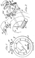
- a tachograph comprises a rear casing 1 having a hinged front casing 2 which acts as a front cover (thefront casing 2 being shown in an open position in Fig. 2).
- a transparent window 3 is fitted to the face of the front casing 2 and through this window can be seen a vehicle speed indicator (pointer 4 and dial 5) and an odometer 6.
- a vehicle speed indicator and an odometer are shown in Figs. 1 and 2 and it should be understood that these Figures are simplified diagrams, since tachographs generally have other various features, such as clock faces, vehicle engine rpm indicators, and so on.
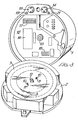
- the rear casing 1 houses a turntable or chart drive on which a tachograph chart 7 is mounted for rotation; styli 8a and 8b for recording respective vehicle speed and distance travelled traces 9 on the tachograph chart 7; and various components (mainly of known construction) which co-operate with the latter parts, in response to transducer pulse input signals, to cause appropriate traces 9 to be recorded on the chart 7.
- the chart drive includes locating pins 10 which engage corresponding holes 11 in the chart 7 and a central spigot 12 which engages a rotary drive member 13 coupled to the shaft of an electrical motor (not shown) housed in the rear casing 1.
- a driver of the vehicle in which the tachograph is fitted can insert the chart 7 on the locating pins 10 and can remove the same after recording.
- Manually selectable controls 13 and 14, which are marked with the usual symbols to represent driver duties to be recorded, are accessible from the exterior of the casing 1 when the front casing 2 is in the closed position. The function of these controls is well known in the art so that no further explanation will be given.
- Fig. 3 has been simplified to show only the speed and distance traces 9, in a schematic fashion, rather than the more usual and more detailed recordings that are associated with contemporary tachograph charts.
- Fig. 2 shows schematically a stepper motor 22 which is coupled (a) through a step-down gear train 22a and shaft 22b to the speed indicating pointer 4, and (b) through a rack and pinion 22c to recording stylus 8a.
- a stepper motor 23 is coupled (a) through a step-down gear train 23a and shaft 23b to odometer 6, and (b) through a cam and lever arrangement 23c to recording stylus 8b which is slidably mounted on a vertical guide 23d.
- the styli 8a and 8b respectively record the speed and distance traces 9 on the chart 7.
- the casing 1 houses a circuit board 15 on which are mounted various components. These components include one or more microprocessors 16 (see below), an 8-position DIL switch 17 to apply a gearbox compensation factor (see below), a 4-position DIL switch 18 for setting a "maximum vehicle speed' (switch 18 is preset by either the manufacturer, or a fitting centre where the tachograph is installed in a vehicle, this switch not being available for adjustment by the vehicle driver), a control e.g. including circuitry mounted on board 15 and operated by a push button 19 on front casing 2 to enable the driver to set a "driver selected top speed" (i.e. a speed below the maximum vehicle speed at which the vehicle is intended to cruise), and various parts of the circuitry and structure.
- a control e.g. including circuitry mounted on board 15 and operated by a push button 19 on front casing 2 to enable the driver to set a "driver selected top speed" (i.e. a speed below the maximum vehicle speed at which the vehicle is intended to
- the control system used in the tachograph is generally illustrated in Fig. 4.
- the system essentially comprises a microprocessor 16 which computes, e.g. vehicle speed and distance travelled on the basis of a pulse input which is proportional to the transmission drive speed of the vehicle and which has been corrected, for example, for the type of gearbox and rear axle fitted to the vehicle.
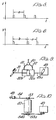
- the pulse input is provided by a pulse generator 25, the pulse repetition frequency or time interval a (Fig. 5) between consecutive pulses being proportional to vehicle speed.
- Fig. 6 indicates that the vehicle is accelerating since the time interval b is longer than a.
- the microprocessor 16 executes (a) a vehicle speed control function, based on the computed vehicle speed, and (b) a display and recording function based on the computed vehicle speed and distance travelled.
- the vehicle speed control function is executed by comparing the corrected vehicle speed input with the preset speed reference (e.g. either the "maximum vehicle speed” reference or the “driver selected top speed” reference) and by supplying an appropriate output, or outputs to an actuator 30 for adjusting the speed of the vehicle.
- Actuator 30 may be of known construction, for example, it may be a pneumatic or pneumatic/hydraulic piston and cylinder arrangement, 30a and 30b, as shown in Fig. 9, wherein a push rod 31 links a throttle pedal 48 to the piston 30a, and a push rod 49a links the cylinder 30b to an adjustable member of a fuel regulating device 49.
- Such an arrangement may be either single acting (e.g.
- Fig. 9 where the piston reacts against a return spring), or double acting (as shown in Fig. 9).
- compressed air is supplied to a valve 50 which is controlled by the microprocessor 16 so as to divert the air to either input 51, or input 52.
- This causes the piston to be respectively advanced to decrease the length of the throttle linkage, or withdrawn to increase the length of the throttle linkage.
- the air pressure is then equalised on each side of piston 30b to provide a rigid link between the pedal 48 and the adjustable member of fuel regulating device 49.
- the piston normally floats at some intermediate point in a cylinder (e.g. with a throttle linkage of normal length), and the piston being driven either one way, or the other to reduce, or extend the throttle linkage and hence regulate the fuel supply to the engine of the vehicle.
- FIG. 10 schematically illustrates an arrangement where pedal 48 is connected to a first pinion 53 by a rack 54.
- Pinion 53 is coupled by an intermediate motor drive 52 to a second pinion 53a.
- Pinion 53a engages a rack 54a connected to the adjusting member of fuel regulating device 49.
- pinions 53 and 53a rotate together, i.e. as if they were mounted on the same shaft.
- the intermediate motor drive 52 can rotate pinion 53a either clockwise, or anticlockwise (either continuously, on in steps) independently of pinion 53, i.e. under control of the microprocessor 16. This effectively shortens or lengthens the linkage between pedal 48 and the adjustable member of fuel regulating device 49.
- the pinions 53 and 53a subsequently rotate in unison to provide throttle control.
- movement of the adjusting member of the fuel regulating device may be limited or regulated, e.g. either continuously or one step at a time, to limit the maximum amount of fuel supplied to the engine.
- the arrangement which is used in practice will depend on the form of control required, e.g. to suit the vehicle characteristics, the terrain on which the vehicle is driven (especially where hills are present), the response (e.g. the time constant of the actuator) and the appropriate output or outputs available from the microprocessor 16.
- the microprocessor causes actuator 30 to remain energised (e.g. to vary the length of the throttle linkage by a predetermined amount) until the computed vehicle speed is equal to the preset speed reference and then the actuator 30 is de-energised.
- the microprocessor energises the actuator so that it returns to its normal position (e.g. the length of the throttle linkage returns to normal).
- the display and recording function (29) is executed by each of the stepper motors 22 and 23 as shown in Fig. 2.
- a 4-phase stepper motor 22 is employed to drive both the speed indicating mechanism connected to pointer 4 and the speed recording mechanism connected to the corresponding stylus 8a.
- the microprocessor 16 positions the pointer 4 by directly controlling the phase sequencing the stepper motor windings.
- Stepper motor 23 drives the odometer mechanism 6 and the corresponding stylus 8b in the same manner.
- Fig. 4 also illustrates means 27 for presetting a maximum vehicles speed and means 28 to enable a driver to select a top speed which is less than the maximum vehicle speed.
- the means 27 include the 4-position DIL switch 18 (Fig. 3) which is preset by the manufacturer or by a fitting center where the tachograph is installed in a vehicle.
- the switch 18 is either isolated, or sealed in such a way that it is normally inaccessible to the driver.
- means 28 include the control 19 which enables the driver to set a top speed, e.g. for limiting the vehicle to a crusing speed which is less than the maximum legal speed at which the vehicle may travel.
- the control 19 may be in the form of a push button which is connected to circuitry which responds, when the button is pressed, to provide an instantaneous value which is used as a driver selected top speed reference. When the button is pressed again, this top speed reference is cancelled and the circuitry is reset to enable a different top speed reference to be selected.
- means 27 and 28 provide maximum speed and top speed reference inputs to the microprocessor 16.
- the microprocessor 16 is also programmed to cause the indicator 21 (Figs. 1-3) to be illuminated each time the driver selected top speed is reached, or exceeded.
- the microprocessor 16 computes the vehicle speed and distance travelled on the basis of a corrected pulse input.
- the 8- position DIL switch 17 enables adjustments to be made to provide a gearbox compensation factor to accommodate differences between vehicles, such as gearbox ratios, rear axle ratios, tyre sizes, etc.
- a switch 24 (Fig. 7) is used which changes state to indicate one or other selected rear axle ratio, thereby providing a further compensation factor.
- These two compensation factors are shown as a correction factor input 26 in Fig. 4.
- the microprocessor 16 is programmed to scan continuously and sequentially the pulse generator input, the states of switches 17, 18 and 24 and the state of control 19 (which provide the correction factor, the maximum speed reference and the driver selected top speed reference), and the states of the stepper motors 22 and 23 (used in the display and recording function), and the state of the actuator 30 (for controlling means for regulating the vehicle speed).
- the scanning rate at which the data inputs are continually updated is such as to ensure smooth control of the vehicle.
- the microprocessor 16 in order to control the speed of the vehicle so that it does not exceed the preset maximum (legal) speed, the microprocessor 16 continually compares the computed vehicle speed with the present maximum speed reference and, when these two data inputs coincide, the microprocessor 16 supplies a control signal to the actuator 30, e.g. to adjust the length of the throttle linkage, so that further vehicle acceleration is inhibited.
- the vehicle will normally start to slow down as soon as the actuator 30 operates and when the true speed drops below the preset maximum speed reference, the microprocessor 16 will cause the actuator 30 to extend the throttle linkage to its normal length thereby allowing the vehicle to accelerate. Effectively, the state of the actuator 30 tends to oscillate about a mean position and the vehicle speed is kept constant within about ⁇ 1 km/hour.
- a similar form of control is applied in order to cause the vehicle to travel at the driver selected top speed (as set by control 19).
- the inertia of the vehicle is the main cause for the vehicle occasionally overshooting the preset speed reference and this is an inevitable effect due to the problem, facing any form of control system, of causing a heavy vehicle smoothly to approach and to maintain a given speed.
- the microprocessor 16 is effectively programmed to learn the vehicle characteristics in practice (i.e. of the vehicle in which the tachograph is installed), and to apply this acquired knowledge so as to provide optimum vehicle speed control.
- the preset speed limit or reference (either 27 or 28 of Fig. 3) is stored as a data which can be effectively reduced in steps, or decremented, each time the computed speed is scanned and found to exceed the preset speed reference.
- the stored data is decremented by 1 km/ hour. If, on a subsequent scan, the computed speed again exceeds the stored preset speed by 1 km/hour or more, then the stored data is again decremented by 1 km/hour. This sequence continues until the computed vehicle speed is equal to or less than the stored preset speed.
- the speed indicating mechanism may need to be recalibrated after the power supply to the system is turned on, or in the event of an error.
- the position of pointer 4 may either be unknown, or not precisely known.
- a microswitch 57 (Fig. 7) is fitted to the speed indicating mechanism so that the microswitch changes state when the pointer 4 is at its zero position. This switch state is used by the microprocessor 16 to recalibrate the setting of pointer 4 so that it accurately displays the computed speed of the vehicle.
- a reset signal may conveniently be derived from the ignition of circuitry of the vehicle so that the system resets as soon as the ignition switch is turned on.
- microprocessor 16a performs all the major functions, i.e. of calculation, vehicle speed control, display and recording, whilst microprocessor 16b provides additional features and, to a large extent, acts only as a monitor of signals generated by microprocessor 16a. Microprocessor 16b can be omitted where these additional features and monitoring are not required.
- the arrangement shown in Fig. 7 can provide a "vehicle distance" pulse output on terminal 32 and a “low speed” output on terminal 33.
- the "distance pulse” output may be supplied to, e.g. a counter-operated switch which changes state each time the vehicle has covered a predetermined distance. Such a switch may operate, for example, a warning light, or some other indicator, to show that some attention is required to the lubrication system, or the braking system, or some other system of the vehicle.
- the "low speed” output may be supplied, for example, to a switch which changes state at a given preset speed of the vehicle.
- the opening of the doors may be inhibited by the switch unless the bus is stationary.
- the switch may also be conditioned, e.g. in the case of a tip-up truck, so that it inhibits elevation of the truck body if the vehicle speed is more than say 8 kph, but enables the truck body to be elevated if the vehicle speed is 5 kph or less.
- the system also has a "serial data" output on terminal 35 and a "speed" pulse output on terminal 34.
- Terminal 35 provides serial data which is transmitted on two wires to external equipment such as an on-bound vehicle computer and/or a magnetic tape or solid state data recorder. Such items are additional to the microprocessor 16 and the display and recording function 29 ofthetachograph.
- Typical serial data to be transmitted includes:
- the "speed" pulse output on terminal 34 is provided for use by external equipment, each pulse being initiated by a corresponding pulse from the pulse generator 25, and the pulse width being a function of the correction factor 26, e.g. set by the gearbox compensation factor switch 17.
- the circuit shown in Fig. 7 is also operable in a self-test mode, e.g. by bridging contacts 36 with a shorting bar whereby the self-test mode functionally tests almost all of the hardware of the tachograph.
- Microprocessor 16a computes road speed and distance travelled as a function of (a) the period between consecutive pulses received on its INT input 37 (the pulse rate is directionally proprtional to road speed), (b) the gearbox compensation factor as set by switch 17, and (c) the state of switch 24 which represents the rear axle ratio used on the vehicle. It also provides outputs to (a) the stepper motor 22, the output of which is coupled to both the speed indicating pointer 4 and the speed recording stylus 8a, and (b) the stepper motor 23, the output of which is coupled to both the odometer 6 and the distance travelled recording stylus 8b.
- the microswitch 57 closes when the pointer 4 is at its zero position and the switch state is used by microprocessor 16a to recalibrate the speed pointer position after the power supply is turned on, or after an error condition.
- a sender conditioner and disconnect sensor 38 receives the output pulses from pulse generator 25.
- the unit 38 filters these pulses, to improve noise immunity, and supplies them to input 39 at microprocessor 16b.
- Microprocessor 16b divides the input pulse frequency by a given factor, e.g. 4 and supplies the pulse divided output to the INT input 37 of microprocessor 16a.
- the unit 38 will respond, if the pulse generator 25 is removed or if its lead is cut, so as to provide a "sender disconnect" signal on input 40 of microprocessor 16a.
- the microprocessor responds by causing the speed indicating pointer 4 to joggle, thereby indicating an error condition.
- a "supply conditioning" circuit 41 removes supply- borne noise and prevents all but the severest "spikes" reaching the microprocessors 16a and 16b.
- a "watch-dog” circuit 42 is incorporated and this uses discrete hardware to monitor the microprocessors 16a, 16b for correct operation. If a fault is detected, both microprocessors are stopped and re-initialised.
- Microprocessors 16a and 16b employ various techniques to validate both their data and program execution. Provided all tests prove negative, the "watch-dog” is held “off” by pulsing a watch-dog output line 43. To minimise external circuitry, “watch-dog” pulses are routed, via output 44 of microprocessor 16b, to the "watch-dog” circuitry 42. A failure of either microprocessor will result in the "watch-dog” being invoked.
- Microprocessor 16b infers vehicle speed by monitoring the phase changes on stepper motor 22 (which is driven by microprocessor 16a and which is coupled to both the speed indicating pointer 4 and the speed recording stylus 8a). During power-up, microprocessor 16b reads the status of the self-test pads 36 and, if shorted, the self-test mode is activated. This mode only affects microprocessor 16b, since microprocessor 16a functions as normal. Microprocessor 16b "fools" microprocessor 16a into displaying road speed, etc., by generating pseudo-transmitter pulses (as if they were from generator 25), and in this way microprocessor 16b exercises the major tachograph functions performed by microprocessor 16a.
- Switch 18 provides a maximum speed reference input to microprocessor 16a
- control 19a (which incorporates push button 19) provides a driver selected top speed reference to microprocessor 16b.
- Control 19a may incorporate a switch having 8 possible settings, e.g. corresponding with speed at increments of 10 kph in the range 50-120 kph. These settings may be selected by the driver, e.g. with the aid of an indicating switch.
- the push button 19 is depressed to provide an instantaneous top speed reference and is pressed again to cancel the same.
- Output 45 provides a speed control signal to the actuator 30 as a result of exceeding either the maximum speed reference or the driver selected top speed reference.
- vehicle speed overshoot may be controlled by continuously decrementing the effective speed reference, e.g. by 1 kph each time the computed vehicle speed exceeds the speed reference by more than 1 kph.
- the microprocessor 16b is programmed to perform such decrementing.
- Actuator 30 may comprise a solenoid valve, since the signal from output 45 has sufficient current sink capability (1 amp max.) to operate most solenoid valves.
- a link option can be provided on the logic board 15 to enable the sense of the output signal to be changed.
- Fig. 8 illustrates the circuitry of the supply monitor and watch-dog unit 42 in more detail.
- Discrete hardware implements the dual function of supply level monitoring and watch-dog controller.
- the supply monitor ensures that the microprocessors 16a, 16b are only allowed to run when the electrical supply to the tachograph is within predetermined limits and has had time to stabilise.
- the watch-dog is concerned with monitoring the microprocessors for correct operation and for initiating an error recovery sequence in the event of a microprocessor failure.
- the circuitry shown in Fig. 8 has the following functions;
- Zener diode Z1, resistor R1, diode D1, capacitor C1 and resistor R2 form the supply monitor.
- diode D1 becomes forward biased and current flows through R2, D1 and R1.
- R1 is smaller than R2, the potential on C1 is low.
- a low on the input of NAND gate U2 forces its output to go high, thereby holding the reset line, connected to its output, in its inactive state.
- zener diode Z1 will eventually start to conduct and pull up the potential on the cathode of diode D1. This results in a corresponding rise in the input of NAND gate U2.
- the watch-dog pulse input of the circuit of Fig. 8 is derived from output 44 of microprocessor 16b.
- the reset output of the circuit of Fig. 5 is applied to the respective inputs 44, 46 of the microprocessors 16b, 16a.
- the microprocessor 16 may be conditioned to control the actuator 30 so that effectively causes the vehicle speed to approach the preset speed in an optimum asymptotic manner. For example, this may be achieved by programming the microprocessor so that it is aware that the vehicle speed is approaching near to the preset speed and so that it provides an appropriate output for controlling an actuator which operates so as to reduce the vehicle speed in sufficient time to avoid overshooting the speed limit.
- a potential overshoot may be predicted with regard to the acceleration of the vehicle at a given instantaneous speed.
- the instantaneous speed can be derived from the frequency of the pulses as mentioned above with reference to Fig.
- the actuator 30 may be controlled in a continuous manner, e.g. by continuously adjusting the extent of the throttle linkage (e.g. by means of the arrangement shown in Figs. 9 or 10), rather than making such adjustments in a stepped manner.
- stepped adjustment is also feasible, e.g. where a larger number of smaller steps are employed.
- Fig. 11 is a plot of vehicle speed v against t and it shows three traces a,-a3 which represents three different rates of acceleration (the slope of the trace being proportional to acceleration). Considering trace a 1 , the vehicle is accelerating smoothly (over the straight line portion) towards a preset speed limit V. At regular instants of time, e.g.
- the microprocessor 16 computes the predicted time required for the vehicle to attain the preset speed V based on data representing instantaneously computed values of vehicle speed and acceleration. These predicted times will vary according to the acceleration of the vehicle (e.g. they will be longer for acceleration a3 than either a 2 or a,). Moreover, the acceleration of the vehicle will depend on the load carried and hence the vehicle speed can be advantageously controlled, with respect to different loads, to avoid exceeding a preset speed limit.
- the predicted times are continuously compared with a selected reference value which is stored in the memory of the microprocessing system.
- This reference value is proportional to the response time, or time constant, of the actuator 30 or the system as a whole (e.g. particularly where the actuator has a fast response) by means of which the supply of fuel to the vehicle engine is adjusted or regulated for controlling vehicle speed. For example, where the extent of the throttle linkage is adjusted to control vehicle speed, there will be a finite delay before the extent of the linkage has been adjusted and has taken effect on vehicle speed.
- the microprocessor is provided with a look-up table containing data relating to vehicle speed, vehicle acceleration and actuator or system response time so that an optimum control function can be provided in accordance with the appropriate input parameters.
- the control function executed by the microprocessor is designed to cause the actuator to reduce vehicle speed on approaching the preset speed limit and to return the actuator to an original or starting position when the vehicle decelerates.
- the speed is reduced at a point which allows the actuator sufficient time to effect a reduction in vehicle speed so that the speed smoothly and assymptotically approaches the preset speed limit V without any significant overshoot.
- a predicted time t is computed or provided from the look-up table to reach speed limit V. This is equivalent to extending the slope of a, to intersect the broken line representing limit V. If t, is substantially equal to the response time of the actuator 30, then microprocessor 16 provides an output to actuator 30 which causes the vehicle speed to be limited smoothly to the preset limit V.
- the tachograph 1 is preferably equipped with means for selecting different preset response times. These response times may be incorporated in the look-up table mentioned above, or means may be provided in the tachograph assembly for selecting different response times.
- Fig. 12 schematically illustrates a modification to tachograph 1 where an additional bank of 8 DIL switches 60 are provided, one of these switches being selected to suit the characteristics of the vehicle. The switches 60 are not normally accessible to the driver, since they would be preselected by a manufacturer, or at a motor depot to suit a particular vehicle.
- control which is provided by the microprocessor 16
- any conventional devices which are necessary or desirable for executing the display and control functions are provided, for example, a clock, ROM, RAM and I/O interfaces.
- the microprocessor program is also adapted for any necessary conversion of analogue inputs to digital data, or digital data to analogue outputs. This applies, for exqmple, to the switches 17,18 and 24, the control 19, and the monitoring of the phases of the stepper motors 22 and 23.
- control 19 being in the form of a push button which is pressed to provide an instantaneous driver selected top speed reference
- depression of the button may cause the microprocessor 16 to scan the stepping phase of stepper motor 22 and to convert the instantaneous analogue signal into a digital data value which is stored in a register.
- the speed reference (either maximum or driver selected) can be stored in a register whereby it can be decremented, e.g. as a result of effectively comparing vehicle speed with the preset speed reference and subtracting a predetermined digital value from the contents of the register whenever the vehicle speed exceeds the preset speed reference (i.e. after each scan as mentioned above).
- microprocessors 16a and 16b the functions provided by these microprocessors may alternatively be carried out by a single microprocessor.
Landscapes
- Engineering & Computer Science (AREA)
- Mechanical Engineering (AREA)
- Transportation (AREA)
- Chemical & Material Sciences (AREA)
- Combustion & Propulsion (AREA)
- General Physics & Mathematics (AREA)
- Physics & Mathematics (AREA)
- Automation & Control Theory (AREA)
- Control Of Vehicle Engines Or Engines For Specific Uses (AREA)
- Steroid Compounds (AREA)
- Controls For Constant Speed Travelling (AREA)
- Control Of Driving Devices And Active Controlling Of Vehicle (AREA)
- Time Recorders, Dirve Recorders, Access Control (AREA)
Abstract
Description
- This invention relates to a vehicle speed control device. In a preferred embodiment of the invention, a tachograph is fitted with a vehicle speed control device having an adjustable control for setting a maximum vehicle speed and another adjustable control for setting a selected vehicle speed which is less than the maximum vehicle speed.
- A problem experienced with vehicle speed control devices is one of "top speed overshoot". This problem is particularly noticeable when the weight of a vehicle changes, e.g. in the case of a fully laden commercial vehicle which is substantially unloaded, or vice versa. If a speed control device fitted to the vehicle is adjusted to suit the characteristics of the vehicle when fully unloaded, the performance of the vehicle will be quite different after it has been fully loaded, (e.g. by as much as 30 tonnes) and vice versa. Similarly, if the same type of vehicle speed control device is fitted to different types of vehicles, the performance of the vehicles will be quite different. In both cases, the speed control device may attempt to govern the vehicle speed to a predetermined maximum limit, but the inertia of the vehicle may cause the maximum speed to be exceeded. This can happen, where, for example, an actuator is employed which is of the type that responds to the vehicle speed control signal in order to adjust a fuel control linkage. A "top speed overshoot" may therefore occur, despite attempts by the vehicle speed control device to govern the actual road speed of the vehicle.
- The invention seeks to overcome these problems and to provide, at least in a preferred arrangement, a vehicle speed control device which is accurate without being unduly complex and expensive to manufacture.
- US-A-4380799 mentiones a basic speed control device in which all mechanical connections between an accelerator pedal and a carburettor have been eliminated, the carburettor being operated by a computer controlled motor. However, it also mentions reinstating a mechanical connection between the accelerator pedal and the carburettor. The mechanical connection includes means for applying friction to the travel of the accelerator pedal and a servomotor with an epicyclic gear train connected to a butterfly valve of the carburettor. The computer provides an output for causing travel of the accelerator pedal to be impeded by applying friction.
- The invention solves the aforementioned problems by providing a vehicle speed control device comprising means to provide a preset speed reference, which relates to a predetermined vehicle speed limit; an input for receiving a signal proportional to vehicle speed; and control means which responds to the vehicle speed input signal and to the preset speed reference, whenever the vehicle speed either exceeds or is about to exceed the vehicle speed limit, and which performs a control function in order to provide an output for reducing the vehicle speed, characterised in that the control means comprises a microprocessor which is programmed to learn the vehicle characteristics and the learning program is effectively reset to an original state whenever the vehicle is used.
- An advantage of the invention is that the microprocessor can be programmed to learn individual vehicle characteristics, e.g. due to differences in vehicle type and/or due to differences in the load- carried by the vehicle, and to exercise an optimum form of speed control. Also, the learning program can be effectively reset to an original state when, for example, the vehicle ignition is turned off.
- The control function which is performed by the control means may be either stepped, or continuous.
- In the case where the vehicle overshoots the speed limit, the vehicle speed may be reduced until it has fallen either to, or just below the speed limit. In the case where the vehicle speed is likelyto exceed the speed limit, (i.e. where an overshoot is predicted, but not experienced), the vehicle speed is ideally reduced so that it gradually approaches the speed limit. In either case and in practice, the vehicle may ultimately achieve a speed which varies slightly from the speed limit, e.g. by oscillating slightly about the speed limit, but such a vehicle speed can be considered as being substantially at the speed limit.
- In the case where the vehicle speed overshoots the speed limit, the control means preferably performs a stepped function to cause a reduction in vehicle speed. One way for the control means to perform such a stepped control function is to employ a "floating" speed reference which is moved downwardly, step by step, each time the vehicle speed input signal is found to exceed the preset speed reference, i.e. for as long as a speed overshoot condition exists. For example, the preset speed reference is first stored (e.g. as a data value). The stored reference and the vehicle speed input signal are then continuously and sequentially scanned to determine (after each scan) whether or not the vehicle speed exceeds the speed limit. The stored reference is then decremented (e.g. by 1 km/hr) whenever the vehicle speed is found to exceed the speed limit. A particular advantage of this arrangement is that the speed reference can be learnt in practice (e.g. on each journey of the vehicle) to suit the individual characteristics of the vehicle (e.g. depending on whether or not it is laden).
- Another way for the control means to perform a stepped control function is to employ an overshoot signal which is proportional to an excess speed, i.e. the amount by which the vehicle speed exceeds the preset speed reference and to use such an overshoot signal to reduce a "floating" speed reference by an amount proportional to the excess speed, and to make this reduction repeatedly until the excess speed has been substantially reduced or eliminated.
- In the case where an overshoot is predicted, action must be taken in sufficient time to prevent an overshoot. One way of making the prediction is to determine vehicle acceleration at instantaneous vehicle speeds and to use such data to compute the time at which an overshoot is likely to occur. For example, the vehicle speed input signal may be derived from a transducer which provides a pulsed output in response to the speed of the transmission of the engine. The interval between consecutive pulses of such a pulsed signal can be used as a measure of vehicle speed and the difference between consecutive pulse intervals can be used as a measure of vehicle acceleration. A vehicle acceleration computed on the basis of the difference between consecutive pulse intervals at a given speed below the preset speed limit will be proportional to the interval of time required to reach the speed limit. Alternatively, the pulse frequency can be differentiated to compute vehicle acceleration, the relationship between computed vehicle acceleration and instantaneous vehicle speed (i.e. the speed of the vehicle when its acceleration was computed) being used to predict the time at which the vehicle speed is likely to reach the preset speed limit. In any such predictive arrangements, the predicted time to reach the preset speed limit can be continually computed and revised so that the control means executes its control function in time to prevent an overshoot and so as to bring the vehicle speed smoothlyto a point at, or closely adjacent the preset speed limit. This may be achieved, for example, by conditioning the control means to provide an output for reducing vehicle speed at a particular point in time which takes into account the response time (or time constant) of an actuator or mechanism fitted to the vehicle for physically adjusting or regulating (e.g) means for controlling the supply offuel to the engine of the vehicle (n.b. examples of such actuators or mechanisms are described below). Where the actuator has a fast response, the response time of the system is taken into account (i.e. to allow time for the speed reducing action to take effect). An advantageouse form of control can be effected by causing the control means to produce its output at a point of time substantially coincident with, or just priorto, the beginning of an interval corresponding with the response time of the actuator or the system.
- Thus, a form of proportional control can be achieved by anticipating when the vehicle is likely to exceed the preset speed limit and by controlling or limiting the vehicle speed in a smooth and optimum manner so that the vehicle speed approaches the preset speed limit asymptotically.
- Generally speaking, various forms of actuator may be employed to reduce vehicle speed. For example, a d.c. motor may be used to provide a continuous (e.g. proportional) control function. Alternatively, a device may be employed to adjust the extent of a throttle linkage and this device could be used in either a continuous, or a stepped manner to effect a change in vehicle speed. More generally, the control means may be linked to a mechanism which regulates vehicle speed with a displacement, series of displacements, frequency, or duty cycle depending on the speed reduction required.
- In the case where an overshoot is predicted, the microprocessor computes the time at which the preset speed limit would be reached on the basis of vehicle acceleration at a given instantaneous speed, or.it may be programmed to keep a watch on vehicle acceleration and to decide when and how an actuator may be controlled to avoid an overshoot.
- In the case where an overshoot occurs and the vehicle speed is decremented until it is at or just below the preset speed limit, the microprocessor is advantageously programmed to learn individual vehicle characteristics, e.g. due to differences in vehicle type, and/or due to differences in the load carried by the vehicle, and to exercise an optimum form of speed control. In such a case, the learning program can be effectively reset to an original state when, for example, the vehicle ignition is turned off. More particularly, the microprocessor may be conditioned to calculate vehicle speed (e.g. from a pulsed output derived from a vehicle speed transducer); to compare the calculated speed with a preset stored speed reference value in order to determine whether or not the vehicle speed has exceeded the preset speed value; and to decrement the stored reference value until any excess vehicle speed has been substantially reduced or eliminated.
- The speed control device may be used in a tachograph to control either the maximum vehicle speed, or a driver selected top speed, or both.
- A tachograph which embodies the invention may have any one or more of the various features mentioned above (as may be required),
- A preferred embodiment of the invention will now be described with reference to the accompanying schematic drawings, in which:
- Fig. 1 is a simplified diagram showing the front of a tachograph,
- Fig. 2 is a simplified perspective view illustrating respective stepper motor drives to vehicle speed display and recording mechanisms, and distance travelled display and recording mechanisms,
- Fig. 3 is a simplified diagram, in perspective, of the tachograph with its hinged cover opened,
- Fig. 4 is a simplified block diagram for illustrating the general system of control and operation used in the tachograph,
- Figs. 5 and 6 are pulse diagrams,
- Fig. 7 is a more detailed block diagram of part of the system shown in Figs. 1-3,
- Fig. 8 is a simplified circuit diagram of a supply monitor and watch-dog circuit used in the system of the tachograph,
- Figs. 9 and 10 are diagrammatic view of other embodiments of the invention, and
- Figs.11 and 12 are respectively a graph and view of a part of the tachograph shown in Fig. 3 which both relate to a further embodiment of the invention.
- Referring to Figs. 1-3, a tachograph comprises a
rear casing 1 having a hingedfront casing 2 which acts as a front cover (thefrontcasing 2 being shown in an open position in Fig. 2). Atransparent window 3 is fitted to the face of thefront casing 2 and through this window can be seen a vehicle speed indicator (pointer 4 and dial 5) and an odometer 6. For simplicity, only a vehicle speed indicator and an odometer are shown in Figs. 1 and 2 and it should be understood that these Figures are simplified diagrams, since tachographs generally have other various features, such as clock faces, vehicle engine rpm indicators, and so on. - The
rear casing 1 houses a turntable or chart drive on which a tachograph chart 7 is mounted for rotation;styli 8a and 8b for recording respective vehicle speed and distance travelled traces 9 on the tachograph chart 7; and various components (mainly of known construction) which co-operate with the latter parts, in response to transducer pulse input signals, to cause appropriate traces 9 to be recorded on the chart 7. The chart drive includes locatingpins 10 which engage correspondingholes 11 in the chart 7 and acentral spigot 12 which engages arotary drive member 13 coupled to the shaft of an electrical motor (not shown) housed in therear casing 1. When thefront casing 2 is in the open position (Fig. 3), a driver of the vehicle (in which the tachograph is fitted) can insert the chart 7 on the locating pins 10 and can remove the same after recording. Manuallyselectable controls casing 1 when thefront casing 2 is in the closed position. The function of these controls is well known in the art so that no further explanation will be given. Moreover, it should be noted that Fig. 3 has been simplified to show only the speed and distance traces 9, in a schematic fashion, rather than the more usual and more detailed recordings that are associated with contemporary tachograph charts. - Fig. 2 shows schematically a
stepper motor 22 which is coupled (a) through a step-downgear train 22a and shaft 22b to thespeed indicating pointer 4, and (b) through a rack and pinion 22c torecording stylus 8a. Similarly, astepper motor 23 is coupled (a) through a step-down gear train 23a and shaft 23b to odometer 6, and (b) through a cam andlever arrangement 23c to recording stylus 8b which is slidably mounted on avertical guide 23d. Thestyli 8a and 8b respectively record the speed and distance traces 9 on the chart 7. - As shown in Fig. 2, the
casing 1 houses acircuit board 15 on which are mounted various components. These components include one or more microprocessors 16 (see below), an 8-position DIL switch 17 to apply a gearbox compensation factor (see below), a 4-position DIL switch 18 for setting a "maximum vehicle speed' (switch 18 is preset by either the manufacturer, or a fitting centre where the tachograph is installed in a vehicle, this switch not being available for adjustment by the vehicle driver), a control e.g. including circuitry mounted onboard 15 and operated by apush button 19 onfront casing 2 to enable the driver to set a "driver selected top speed" (i.e. a speed below the maximum vehicle speed at which the vehicle is intended to cruise), and various parts of the circuitry and structure. - The control system used in the tachograph is generally illustrated in Fig. 4. The system essentially comprises a
microprocessor 16 which computes, e.g. vehicle speed and distance travelled on the basis of a pulse input which is proportional to the transmission drive speed of the vehicle and which has been corrected, for example, for the type of gearbox and rear axle fitted to the vehicle. The pulse input is provided by apulse generator 25, the pulse repetition frequency or time interval a (Fig. 5) between consecutive pulses being proportional to vehicle speed. Fig. 6 indicates that the vehicle is accelerating since the time interval b is longer than a. - The
microprocessor 16 executes (a) a vehicle speed control function, based on the computed vehicle speed, and (b) a display and recording function based on the computed vehicle speed and distance travelled. - More specifically, the vehicle speed control function is executed by comparing the corrected vehicle speed input with the preset speed reference (e.g. either the "maximum vehicle speed" reference or the "driver selected top speed" reference) and by supplying an appropriate output, or outputs to an
actuator 30 for adjusting the speed of the vehicle.Actuator 30 may be of known construction, for example, it may be a pneumatic or pneumatic/hydraulic piston and cylinder arrangement, 30a and 30b, as shown in Fig. 9, wherein apush rod 31 links athrottle pedal 48 to thepiston 30a, and apush rod 49a links the cylinder 30b to an adjustable member of afuel regulating device 49. Such an arrangement may be either single acting (e.g. where the piston reacts against a return spring), or double acting (as shown in Fig. 9). In the double acting arrangement of Fig. 9, compressed air is supplied to a valve 50 which is controlled by themicroprocessor 16 so as to divert the air to eitherinput 51, orinput 52. This causes the piston to be respectively advanced to decrease the length of the throttle linkage, or withdrawn to increase the length of the throttle linkage. The air pressure is then equalised on each side of piston 30b to provide a rigid link between the pedal 48 and the adjustable member offuel regulating device 49. Thus, the piston normally floats at some intermediate point in a cylinder (e.g. with a throttle linkage of normal length), and the piston being driven either one way, or the other to reduce, or extend the throttle linkage and hence regulate the fuel supply to the engine of the vehicle. - A further alternative is to use a motor driven actuator in the throttle linkage to regulate maximum vehicle speed. Fig. 10 schematically illustrates an arrangement where
pedal 48 is connected to a first pinion 53 by arack 54. Pinion 53 is coupled by anintermediate motor drive 52 to asecond pinion 53a.Pinion 53a engages arack 54a connected to the adjusting member offuel regulating device 49. Normally, pinions 53 and 53a rotate together, i.e. as if they were mounted on the same shaft. However, theintermediate motor drive 52 can rotatepinion 53a either clockwise, or anticlockwise (either continuously, on in steps) independently of pinion 53, i.e. under control of themicroprocessor 16. This effectively shortens or lengthens the linkage betweenpedal 48 and the adjustable member offuel regulating device 49. Thepinions 53 and 53a subsequently rotate in unison to provide throttle control. - In a more simple arrangement, movement of the adjusting member of the fuel regulating device may be limited or regulated, e.g. either continuously or one step at a time, to limit the maximum amount of fuel supplied to the engine.
- The arrangement which is used in practice will depend on the form of control required, e.g. to suit the vehicle characteristics, the terrain on which the vehicle is driven (especially where hills are present), the response (e.g. the time constant of the actuator) and the appropriate output or outputs available from the
microprocessor 16. - In its simplest form, the microprocessor causes
actuator 30 to remain energised (e.g. to vary the length of the throttle linkage by a predetermined amount) until the computed vehicle speed is equal to the preset speed reference and then theactuator 30 is de-energised. When the computed vehicle speed eventually falls below the preset speed reference, e.g. when the vehicle decelerates, the microprocessor energises the actuator so that it returns to its normal position (e.g. the length of the throttle linkage returns to normal). - The display and recording function (29) is executed by each of the
stepper motors phase stepper motor 22 is employed to drive both the speed indicating mechanism connected topointer 4 and the speed recording mechanism connected to thecorresponding stylus 8a. Themicroprocessor 16 positions thepointer 4 by directly controlling the phase sequencing the stepper motor windings.Stepper motor 23 drives the odometer mechanism 6 and the corresponding stylus 8b in the same manner. - Fig. 4 also illustrates means 27 for presetting a maximum vehicles speed and means 28 to enable a driver to select a top speed which is less than the maximum vehicle speed. The means 27 include the 4-position DIL switch 18 (Fig. 3) which is preset by the manufacturer or by a fitting center where the tachograph is installed in a vehicle. The
switch 18 is either isolated, or sealed in such a way that it is normally inaccessible to the driver. However, means 28 include thecontrol 19 which enables the driver to set a top speed, e.g. for limiting the vehicle to a crusing speed which is less than the maximum legal speed at which the vehicle may travel. Thecontrol 19 may be in the form of a push button which is connected to circuitry which responds, when the button is pressed, to provide an instantaneous value which is used as a driver selected top speed reference. When the button is pressed again, this top speed reference is cancelled and the circuitry is reset to enable a different top speed reference to be selected. Hence, means 27 and 28 provide maximum speed and top speed reference inputs to themicroprocessor 16. - The
microprocessor 16 is also programmed to cause the indicator 21 (Figs. 1-3) to be illuminated each time the driver selected top speed is reached, or exceeded. - As mentioned above, the
microprocessor 16 computes the vehicle speed and distance travelled on the basis of a corrected pulse input. The 8-position DIL switch 17 enables adjustments to be made to provide a gearbox compensation factor to accommodate differences between vehicles, such as gearbox ratios, rear axle ratios, tyre sizes, etc. When the vehicle is fitted with dual axle transmission system, a switch 24 (Fig. 7) is used which changes state to indicate one or other selected rear axle ratio, thereby providing a further compensation factor. These two compensation factors are shown as a correction factor input 26 in Fig. 4. - The
microprocessor 16 is programmed to scan continuously and sequentially the pulse generator input, the states ofswitches stepper motors 22 and 23 (used in the display and recording function), and the state of the actuator 30 (for controlling means for regulating the vehicle speed). The scanning rate at which the data inputs are continually updated is such as to ensure smooth control of the vehicle. - Generally speaking, in order to control the speed of the vehicle so that it does not exceed the preset maximum (legal) speed, the
microprocessor 16 continually compares the computed vehicle speed with the present maximum speed reference and, when these two data inputs coincide, themicroprocessor 16 supplies a control signal to theactuator 30, e.g. to adjust the length of the throttle linkage, so that further vehicle acceleration is inhibited. The vehicle will normally start to slow down as soon as theactuator 30 operates and when the true speed drops below the preset maximum speed reference, themicroprocessor 16 will cause theactuator 30 to extend the throttle linkage to its normal length thereby allowing the vehicle to accelerate. Effectively, the state of theactuator 30 tends to oscillate about a mean position and the vehicle speed is kept constant within about ±1 km/hour. - A similar form of control is applied in order to cause the vehicle to travel at the driver selected top speed (as set by control 19).
- The inertia of the vehicle is the main cause for the vehicle occasionally overshooting the preset speed reference and this is an inevitable effect due to the problem, facing any form of control system, of causing a heavy vehicle smoothly to approach and to maintain a given speed. To offset this, the
microprocessor 16 is effectively programmed to learn the vehicle characteristics in practice (i.e. of the vehicle in which the tachograph is installed), and to apply this acquired knowledge so as to provide optimum vehicle speed control. As part of this learning process, the preset speed limit or reference (either 27 or 28 of Fig. 3) is stored as a data which can be effectively reduced in steps, or decremented, each time the computed speed is scanned and found to exceed the preset speed reference. For example, if on a first scan the computed speed exceeds the stored preset speed reference data by 1 km/hour or more, the stored data is decremented by 1 km/ hour. If, on a subsequent scan, the computed speed again exceeds the stored preset speed by 1 km/hour or more, then the stored data is again decremented by 1 km/hour. This sequence continues until the computed vehicle speed is equal to or less than the stored preset speed. - The speed indicating mechanism (pointer 4) may need to be recalibrated after the power supply to the system is turned on, or in the event of an error. For example, the position of
pointer 4 may either be unknown, or not precisely known. To overcome this problem, a microswitch 57 (Fig. 7) is fitted to the speed indicating mechanism so that the microswitch changes state when thepointer 4 is at its zero position. This switch state is used by themicroprocessor 16 to recalibrate the setting ofpointer 4 so that it accurately displays the computed speed of the vehicle. - With regard to resetting the
microprocessor 16, a reset signal may conveniently be derived from the ignition of circuitry of the vehicle so that the system resets as soon as the ignition switch is turned on. - Turning now to Figs. 7 and 8, a more detailed block diagram of part of the system shown in Fig. 4, together with a supply monitor and watch-dog circuit used in the system, will now be described. Similar reference numerals have been used to identify like components and, in this case, two
microprocessors 16a and 16b are employed. Essentially,microprocessor 16a performs all the major functions, i.e. of calculation, vehicle speed control, display and recording, whilst microprocessor 16b provides additional features and, to a large extent, acts only as a monitor of signals generated bymicroprocessor 16a. Microprocessor 16b can be omitted where these additional features and monitoring are not required. - In addition to the functions described above, the arrangement shown in Fig. 7 can provide a "vehicle distance" pulse output on
terminal 32 and a "low speed" output onterminal 33. The "distance pulse" output may be supplied to, e.g. a counter-operated switch which changes state each time the vehicle has covered a predetermined distance. Such a switch may operate, for example, a warning light, or some other indicator, to show that some attention is required to the lubrication system, or the braking system, or some other system of the vehicle. The "low speed" output may be supplied, for example, to a switch which changes state at a given preset speed of the vehicle. For example, where the tachograph is fitted to a bus where the doors can be opened by the passengers, the opening of the doors may be inhibited by the switch unless the bus is stationary. The switch may also be conditioned, e.g. in the case of a tip-up truck, so that it inhibits elevation of the truck body if the vehicle speed is more than say 8 kph, but enables the truck body to be elevated if the vehicle speed is 5 kph or less. The system also has a "serial data" output onterminal 35 and a "speed" pulse output onterminal 34.Terminal 35 provides serial data which is transmitted on two wires to external equipment such as an on-bound vehicle computer and/or a magnetic tape or solid state data recorder. Such items are additional to themicroprocessor 16 and the display andrecording function 29 ofthetachograph. Typical serial data to be transmitted includes: - a) the position of the
speed pointer 4, - b) the setting of the DIL switches 17 and/or 18 (read by microprocessor 16b),
- c) the status of various input signals to
microprocessor 16a (to which microprocessor 16b has access), - d) a check sum, which can be used by external equipment to validate received data.
- The "speed" pulse output on
terminal 34 is provided for use by external equipment, each pulse being initiated by a corresponding pulse from thepulse generator 25, and the pulse width being a function of the correction factor 26, e.g. set by the gearboxcompensation factor switch 17. - The circuit shown in Fig. 7 is also operable in a self-test mode, e.g. by bridging
contacts 36 with a shorting bar whereby the self-test mode functionally tests almost all of the hardware of the tachograph. -
Microprocessor 16a computes road speed and distance travelled as a function of (a) the period between consecutive pulses received on its INT input 37 (the pulse rate is directionally proprtional to road speed), (b) the gearbox compensation factor as set byswitch 17, and (c) the state ofswitch 24 which represents the rear axle ratio used on the vehicle. It also provides outputs to (a) thestepper motor 22, the output of which is coupled to both thespeed indicating pointer 4 and thespeed recording stylus 8a, and (b) thestepper motor 23, the output of which is coupled to both the odometer 6 and the distance travelled recording stylus 8b. Themicroswitch 57, closes when thepointer 4 is at its zero position and the switch state is used bymicroprocessor 16a to recalibrate the speed pointer position after the power supply is turned on, or after an error condition. - A sender conditioner and disconnect
sensor 38 receives the output pulses frompulse generator 25. Theunit 38 filters these pulses, to improve noise immunity, and supplies them to input 39 at microprocessor 16b. Microprocessor 16b divides the input pulse frequency by a given factor, e.g. 4 and supplies the pulse divided output to theINT input 37 ofmicroprocessor 16a. - The
unit 38 will respond, if thepulse generator 25 is removed or if its lead is cut, so as to provide a "sender disconnect" signal oninput 40 ofmicroprocessor 16a. The microprocessor responds by causing thespeed indicating pointer 4 to joggle, thereby indicating an error condition. - As the system employs digital techniques, it is inherently vulnerable to electrical noise. A "supply conditioning"
circuit 41 removes supply- borne noise and prevents all but the severest "spikes" reaching themicroprocessors 16a and 16b. To further improve the instrument's tolerance to noise, a "watch-dog"circuit 42 is incorporated and this uses discrete hardware to monitor themicroprocessors 16a, 16b for correct operation. If a fault is detected, both microprocessors are stopped and re-initialised.Microprocessors 16a and 16b employ various techniques to validate both their data and program execution. Provided all tests prove negative, the "watch-dog" is held "off" by pulsing a watch-dog output line 43. To minimise external circuitry, "watch-dog" pulses are routed, viaoutput 44 of microprocessor 16b, to the "watch-dog"circuitry 42. A failure of either microprocessor will result in the "watch-dog" being invoked. - Microprocessor 16b infers vehicle speed by monitoring the phase changes on stepper motor 22 (which is driven by
microprocessor 16a and which is coupled to both thespeed indicating pointer 4 and thespeed recording stylus 8a). During power-up, microprocessor 16b reads the status of the self-test pads 36 and, if shorted, the self-test mode is activated. This mode only affects microprocessor 16b, sincemicroprocessor 16a functions as normal. Microprocessor 16b "fools"microprocessor 16a into displaying road speed, etc., by generating pseudo-transmitter pulses (as if they were from generator 25), and in this way microprocessor 16b exercises the major tachograph functions performed bymicroprocessor 16a. -
Switch 18 provides a maximum speed reference input tomicroprocessor 16a, andcontrol 19a (which incorporates push button 19) provides a driver selected top speed reference to microprocessor 16b.Control 19a may incorporate a switch having 8 possible settings, e.g. corresponding with speed at increments of 10 kph in the range 50-120 kph. These settings may be selected by the driver, e.g. with the aid of an indicating switch. Alternatively, and as mentioned above, thepush button 19 is depressed to provide an instantaneous top speed reference and is pressed again to cancel the same. -
Output 45 provides a speed control signal to theactuator 30 as a result of exceeding either the maximum speed reference or the driver selected top speed reference. In either case, vehicle speed overshoot may be controlled by continuously decrementing the effective speed reference, e.g. by 1 kph each time the computed vehicle speed exceeds the speed reference by more than 1 kph. The microprocessor 16b is programmed to perform such decrementing. -
Actuator 30 may comprise a solenoid valve, since the signal fromoutput 45 has sufficient current sink capability (1 amp max.) to operate most solenoid valves. To accommodate different actuator mechanisms, a link option can be provided on thelogic board 15 to enable the sense of the output signal to be changed. - Fig. 8 illustrates the circuitry of the supply monitor and watch-
dog unit 42 in more detail. Discrete hardware implements the dual function of supply level monitoring and watch-dog controller. The supply monitor ensures that themicroprocessors 16a, 16b are only allowed to run when the electrical supply to the tachograph is within predetermined limits and has had time to stabilise. The watch-dog is concerned with monitoring the microprocessors for correct operation and for initiating an error recovery sequence in the event of a microprocessor failure. The circuitry shown in Fig. 8 has the following functions; - a) a reset timer (to ensure an adequate reset pulse for the microprocessors),
- b) supply monitor (to hold the microprocessors in their reset state if the supply voltage falls below e.g. approximately 8.5 volts), and
- c) watch-dog monitor (which forces both microprocessors into their reset state if their watch-dog pulses should stop).
- Zener diode Z1, resistor R1, diode D1, capacitor C1 and resistor R2 form the supply monitor. When the supply voltage is low (e.g. less than 3.3 volts), diode D1 becomes forward biased and current flows through R2, D1 and R1. As R1 is smaller than R2, the potential on C1 is low. A low on the input of NAND gate U2 forces its output to go high, thereby holding the reset line, connected to its output, in its inactive state. As the supply (B) starts to rise, zener diode Z1 will eventually start to conduct and pull up the potential on the cathode of diode D1. This results in a corresponding rise in the input of NAND gate U2. As the supply (B) exceeds approximately 8.5 volts, the input to U2 will have risen sufficiently to release the reset line. The time constant formed by R2 and C1 ensures an adequate delay in releasing the reset line if the supply (B) should rise sharply. U2, C2 and R3 form a slow-running Schmitt oscillator.
- In the absence of watch-dog pulses, the output of gate U1 is held low. Diode D2 is therefore permanently reverse biased. U2 oscillates, raising and lowering the microprocessors' reset lines. Each time the microprocessors are released, they should start to output watch-dog pulses to C3. After differentiation by R4 and C3, these pulses will appear on the output of U1. Each time the output U1 swings high, D2 becomes forward biased and dumps charge into C2. C2 is pumped up until it sits permanently high, preventing further oscillation of U1. If either microprocessor detects an internal error, its respective watch-dog output goes inactive. U1 starts on its first cycle of oscillation and re-initialises both microprocessors.
- The watch-dog pulse input of the circuit of Fig. 8 is derived from
output 44 of microprocessor 16b. The reset output of the circuit of Fig. 5 is applied to therespective inputs microprocessors 16b, 16a. - By way of an alternative to decrementing preset speed reference data whenever the vehicle speed exceeds the preset speed, the
microprocessor 16 may be conditioned to control theactuator 30 so that effectively causes the vehicle speed to approach the preset speed in an optimum asymptotic manner. For example, this may be achieved by programming the microprocessor so that it is aware that the vehicle speed is approaching near to the preset speed and so that it provides an appropriate output for controlling an actuator which operates so as to reduce the vehicle speed in sufficient time to avoid overshooting the speed limit. A potential overshoot may be predicted with regard to the acceleration of the vehicle at a given instantaneous speed. The instantaneous speed can be derived from the frequency of the pulses as mentioned above with reference to Fig. 5 and the acceleration of the vehicle can be deduced from the interval between pulses as mentioned with reference to Fig. 6 (e.g. a reduction in the interval between pulses, where b is greater than a, means that the vehicle is accelerating). Thus, the difference between concurrent intervals is a measure of vehicle acceleration and this can be used, together with a measure of instantaneous speed, for proportionally adjusting the movement of theactuator 30 so that the vehicle smoothly approaches, but does not exceed the preset speed limit. In this case, theactuator 30 may be controlled in a continuous manner, e.g. by continuously adjusting the extent of the throttle linkage (e.g. by means of the arrangement shown in Figs. 9 or 10), rather than making such adjustments in a stepped manner. However, stepped adjustment is also feasible, e.g. where a larger number of smaller steps are employed. - Instead of deducing vehicle acceleration from the pulse interval (shown in Fig. 6), it may be computed by differentiating the pulse frequency. More particularly, the pulse output of pulse generator 25 (Fig. 4) provides a signal having a frequency proportional to vehicle speed, and this signal is differentiated (e.g. by a differentiating circuit or by a suitably programmed microprocessor) to provide data which is proportional to vehicle acceleration. Fig. 11 is a plot of vehicle speed v against t and it shows three traces a,-a3 which represents three different rates of acceleration (the slope of the trace being proportional to acceleration). Considering trace a1, the vehicle is accelerating smoothly (over the straight line portion) towards a preset speed limit V. At regular instants of time, e.g. above a predetermined speed threshold, the
microprocessor 16 computes the predicted time required for the vehicle to attain the preset speed V based on data representing instantaneously computed values of vehicle speed and acceleration. These predicted times will vary according to the acceleration of the vehicle (e.g. they will be longer for acceleration a3 than either a2 or a,). Moreover, the acceleration of the vehicle will depend on the load carried and hence the vehicle speed can be advantageously controlled, with respect to different loads, to avoid exceeding a preset speed limit. - The predicted times are continuously compared with a selected reference value which is stored in the memory of the microprocessing system. This reference value is proportional to the response time, or time constant, of the
actuator 30 or the system as a whole (e.g. particularly where the actuator has a fast response) by means of which the supply of fuel to the vehicle engine is adjusted or regulated for controlling vehicle speed. For example, where the extent of the throttle linkage is adjusted to control vehicle speed, there will be a finite delay before the extent of the linkage has been adjusted and has taken effect on vehicle speed. - Preferably, the microprocessor is provided with a look-up table containing data relating to vehicle speed, vehicle acceleration and actuator or system response time so that an optimum control function can be provided in accordance with the appropriate input parameters.
- In any such arrangements, the control function executed by the microprocessor is designed to cause the actuator to reduce vehicle speed on approaching the preset speed limit and to return the actuator to an original or starting position when the vehicle decelerates. During acceleration, the speed is reduced at a point which allows the actuator sufficient time to effect a reduction in vehicle speed so that the speed smoothly and assymptotically approaches the preset speed limit V without any significant overshoot. For example, at point x on trace a" a predicted time t, is computed or provided from the look-up table to reach speed limit V. This is equivalent to extending the slope of a, to intersect the broken line representing limit V. If t, is substantially equal to the response time of the
actuator 30, thenmicroprocessor 16 provides an output to actuator 30 which causes the vehicle speed to be limited smoothly to the preset limit V. - As different vehicles and/or different actuators will respond within different time intervals, the
tachograph 1 is preferably equipped with means for selecting different preset response times. These response times may be incorporated in the look-up table mentioned above, or means may be provided in the tachograph assembly for selecting different response times. In the latter respect, Fig. 12 schematically illustrates a modification totachograph 1 where an additional bank of 8 DIL switches 60 are provided, one of these switches being selected to suit the characteristics of the vehicle. Theswitches 60 are not normally accessible to the driver, since they would be preselected by a manufacturer, or at a motor depot to suit a particular vehicle. - With general regard to the form of control which is provided by the
microprocessor 16, it will be understood that any conventional devices which are necessary or desirable for executing the display and control functions are provided, for example, a clock, ROM, RAM and I/O interfaces. Moreover, the microprocessor program is also adapted for any necessary conversion of analogue inputs to digital data, or digital data to analogue outputs. This applies, for exqmple, to theswitches control 19, and the monitoring of the phases of thestepper motors control 19 being in the form of a push button which is pressed to provide an instantaneous driver selected top speed reference, depression of the button may cause themicroprocessor 16 to scan the stepping phase ofstepper motor 22 and to convert the instantaneous analogue signal into a digital data value which is stored in a register. The speed reference (either maximum or driver selected) can be stored in a register whereby it can be decremented, e.g. as a result of effectively comparing vehicle speed with the preset speed reference and subtracting a predetermined digital value from the contents of the register whenever the vehicle speed exceeds the preset speed reference (i.e. after each scan as mentioned above). As those skilled in the art will be familiar with microprocessing technniques, no further detailed description will be given. - In the embodiment described above with reference to Fig. 7, i.e. where
microprocessors 16a and 16b are used, the functions provided by these microprocessors may alternatively be carried out by a single microprocessor.
Claims (14)
Priority Applications (1)
| Application Number | Priority Date | Filing Date | Title |
|---|---|---|---|
| AT85301191T ATE58255T1 (en) | 1984-02-24 | 1985-02-22 | DEVICE FOR CONTROLLING VEHICLE SPEED. |
Applications Claiming Priority (2)
| Application Number | Priority Date | Filing Date | Title |
|---|---|---|---|
| GB8404888 | 1984-02-24 | ||
| GB848404888A GB8404888D0 (en) | 1984-02-24 | 1984-02-24 | Tachograph |
Related Child Applications (2)
| Application Number | Title | Priority Date | Filing Date |
|---|---|---|---|
| EP89202700.4 Division-Into | 1985-02-22 | ||
| EP19890202700 Division EP0362969A3 (en) | 1984-02-24 | 1985-02-22 | Tachograph and vehicle speed control device |
Publications (3)
| Publication Number | Publication Date |
|---|---|
| EP0154459A2 EP0154459A2 (en) | 1985-09-11 |
| EP0154459A3 EP0154459A3 (en) | 1986-11-05 |
| EP0154459B1 true EP0154459B1 (en) | 1990-11-07 |
Family
ID=10557131
Family Applications (1)
| Application Number | Title | Priority Date | Filing Date |
|---|---|---|---|
| EP85301191A Expired - Lifetime EP0154459B1 (en) | 1984-02-24 | 1985-02-22 | Vehicle speed control device |
Country Status (5)
| Country | Link |
|---|---|
| US (1) | US4858135A (en) |
| EP (1) | EP0154459B1 (en) |
| AT (1) | ATE58255T1 (en) |
| DE (1) | DE3580378D1 (en) |
| GB (1) | GB8404888D0 (en) |
Families Citing this family (33)
| Publication number | Priority date | Publication date | Assignee | Title |
|---|---|---|---|---|
| DE3536330A1 (en) * | 1985-10-11 | 1987-04-16 | Mannesmann Kienzle Gmbh | SPEED LIMITER |
| DE3543163A1 (en) * | 1985-12-06 | 1987-06-11 | Mannesmann Kienzle Gmbh | SPEED LIMITER |
| EP0234490B1 (en) * | 1986-02-22 | 1992-06-03 | Mannesmann Kienzle GmbH | Speed limiter for an automotive vehicle |
| US4733644A (en) * | 1986-05-22 | 1988-03-29 | Brunswick Corporation | Engine overspeed control circuit with defeat detection |
| GB8620596D0 (en) * | 1986-08-26 | 1986-10-01 | Veeder Root Ltd | Tachograph |
| JPH061860Y2 (en) * | 1988-10-31 | 1994-01-19 | 自動車電機工業株式会社 | Automatic vehicle speed controller |
| JP2634668B2 (en) * | 1989-05-30 | 1997-07-30 | 日産自動車株式会社 | Automatic vehicle speed control |
| DE3930862A1 (en) * | 1989-09-15 | 1991-03-28 | Vdo Schindling | METHOD AND DEVICE FOR PRESENTING AIRPORT INFORMATION |
| US5420793A (en) * | 1991-08-09 | 1995-05-30 | Ford Motor Company | Vehicle speed control system with quadratic feedback control |
| GB9202676D0 (en) * | 1992-02-08 | 1992-03-25 | Massey Ferguson Sa | Vehicle road speed control system |
| DE4222997A1 (en) * | 1992-07-13 | 1994-01-20 | Strasser Spezialtransporte Gmb | vehicle speed and=or engine revolution rate limiter - involves controlling engine operating parameter according to maximum permissible and measured values |
| US6044315A (en) * | 1996-06-13 | 2000-03-28 | Prince Corporation | Vehicle non-volatile memory system |
| WO1998000635A2 (en) * | 1996-06-21 | 1998-01-08 | Outboard Marine Corporation | Method and apparatus for creating a profile of operating conditions of an engine |
| DE19646104C1 (en) * | 1996-11-08 | 1998-04-02 | Bosch Gmbh Robert | Device for selecting and displaying speeds |
| US5869776A (en) * | 1997-02-26 | 1999-02-09 | Kuhlman Corporation | Method and apparatus for receiving and displaying digital data |
| DE10041745A1 (en) * | 2000-08-25 | 2002-03-07 | Bayerische Motoren Werke Ag | Selector device for setting the driving speed of a vehicle |
| JP3881177B2 (en) * | 2001-02-06 | 2007-02-14 | 三菱電機株式会社 | Vehicle control device |
| DE10154385A1 (en) * | 2001-11-06 | 2003-05-15 | Opel Adam Ag | Device and method for speed control in a motor vehicle |
| DE10256717A1 (en) * | 2002-12-04 | 2004-06-24 | Siemens Ag | gear unit |
| USRE47986E1 (en) | 2003-05-15 | 2020-05-12 | Speedgauge, Inc. | System and method for evaluating vehicle and operator performance |
| TWI268347B (en) * | 2005-07-25 | 2006-12-11 | Sin Etke Technology Co Ltd | Devices of speed of a motor vehicle with concurrent selector accumulative value being substituted into the convertible function to compute a practical value |
| US9493171B2 (en) * | 2008-10-30 | 2016-11-15 | Ford Global Technologies, Llc | Vehicle and method of advising a driver therein |
| DE102008061710A1 (en) * | 2008-12-12 | 2010-06-17 | Continental Automotive Gmbh | Method for operating a sensor device and sensor device |
| US8738228B2 (en) | 2009-10-30 | 2014-05-27 | Ford Global Technologies, Llc | Vehicle and method of tuning performance of same |
| US8258934B2 (en) * | 2009-10-30 | 2012-09-04 | Ford Global Technologies, Llc | Vehicle and method of advising a driver therein |
| US8886365B2 (en) * | 2009-10-30 | 2014-11-11 | Ford Global Technologies, Llc | Vehicle and method for advising driver of same |
| KR101256315B1 (en) * | 2011-10-18 | 2013-04-18 | 엘에스산전 주식회사 | Apparatus and method for controlling train speed |
| US8977430B2 (en) * | 2012-12-26 | 2015-03-10 | Robert Bosch Gmbh | Electronic stability control system indicator |
| KR101583878B1 (en) * | 2013-11-15 | 2016-01-08 | 엘에스산전 주식회사 | Apparatus for controlling speed in railway vehicles |
| KR101866610B1 (en) * | 2014-09-17 | 2018-06-11 | 엘에스산전 주식회사 | Apparatus for Warning of Exceeding Speed Limit in Railway Vehicles |
| US10609654B2 (en) * | 2016-11-09 | 2020-03-31 | Qualcomm Incorporated | Indexing cellular V2X coverage range to vehicle speed |
| CN106347544A (en) * | 2016-11-24 | 2017-01-25 | 天津市中环电子计算机有限公司 | Electric bicycle running displayer with photoelectric induction function and control method |
| US11097727B2 (en) * | 2019-03-11 | 2021-08-24 | GM Global Technology Operations LLC | Eco-cruise: torque management |
Family Cites Families (13)
| Publication number | Priority date | Publication date | Assignee | Title |
|---|---|---|---|---|
| DE2104351C3 (en) * | 1971-01-30 | 1974-04-11 | Kienzle Apparate Gmbh, 7730 Villingen | Device for the automatic evaluation of diagrams |
| DE2208468C3 (en) * | 1972-02-23 | 1975-05-15 | Kienzle Apparate Gmbh, 7730 Villingen-Schwenningen | Arrangement for the control of recording processes in a tachograph or similar recording device |
| CA1101552A (en) * | 1976-04-08 | 1981-05-19 | Emanuel S. Weisbart | Digital tachograph system with digital memory system |
| US4074196A (en) * | 1976-08-02 | 1978-02-14 | Webster Douglas G | Speedometer and odometer apparatus |
| FR2460224A1 (en) * | 1979-06-29 | 1981-01-23 | Renault | PULSE REGULATOR FOR MOTOR VEHICLE |
| ZA814691B (en) * | 1980-08-08 | 1983-02-23 | Ass Eng Ltd | Automatic speed control systems |
| US4374422A (en) * | 1980-10-27 | 1983-02-15 | The Bendix Corporation | Automatic speed control for heavy vehicles |
| US4463822A (en) * | 1981-05-27 | 1984-08-07 | Fujitsu Ten Limited | Cruise control system for automotive vehicle |
| US4537272A (en) * | 1982-01-25 | 1985-08-27 | Fujitsu Ten Limited | Automotive vehicle speed control device based on a preselected speed |
| US4598370A (en) * | 1983-01-27 | 1986-07-01 | Honda Giken Kogyo Kabushiki Kaisha | Apparatus for control of acceleration and deceleration during auto-cruise |
| GB2136164B (en) * | 1983-03-01 | 1987-03-25 | Aisin Seiki | Automobile speed control systems |
| DE3307523A1 (en) * | 1983-03-03 | 1984-09-06 | Kienzle Apparate Gmbh, 7730 Villingen-Schwenningen | TACHOGRAPH FOR MOTOR VEHICLES |
| EP0129949A3 (en) * | 1983-06-17 | 1985-11-06 | Fleetmaster (Proprietary) Limited | Vehicle monitoring system |
-
1984
- 1984-02-24 GB GB848404888A patent/GB8404888D0/en active Pending
-
1985
- 1985-02-22 EP EP85301191A patent/EP0154459B1/en not_active Expired - Lifetime
- 1985-02-22 DE DE8585301191T patent/DE3580378D1/en not_active Expired - Fee Related
- 1985-02-22 AT AT85301191T patent/ATE58255T1/en not_active IP Right Cessation
-
1987
- 1987-10-09 US US07/107,924 patent/US4858135A/en not_active Expired - Fee Related
Also Published As
| Publication number | Publication date |
|---|---|
| DE3580378D1 (en) | 1990-12-13 |
| GB8404888D0 (en) | 1984-03-28 |
| ATE58255T1 (en) | 1990-11-15 |
| US4858135A (en) | 1989-08-15 |
| EP0154459A3 (en) | 1986-11-05 |
| EP0154459A2 (en) | 1985-09-11 |
Similar Documents
| Publication | Publication Date | Title |
|---|---|---|
| US4858135A (en) | Tachograph and vehicle speed control device | |
| US5703776A (en) | Method and device for measuring slope of driving road | |
| EP0121937B1 (en) | Accelerator pedal control system for automotive vehicle | |
| EP0121938B1 (en) | Throttle control system for automotive vehicle | |
| KR910000577B1 (en) | Automatic Oscillation Control Device for Internal Combustion Engine Vehicle | |
| EP0114401B1 (en) | Accelerator control system for automotive vehicle | |
| US5033431A (en) | Method of learning gain for throttle control motor | |
| US5447134A (en) | Throttle valve control system for engine | |
| US4523564A (en) | Road and engine speed governor | |
| JPS6357341A (en) | Constant speed travel device for vehicle | |
| US5552985A (en) | Cruising control apparatus | |
| US5388562A (en) | Fuel injection control system for internal combustion engine | |
| US4586403A (en) | Adaptively calibrated sensing mechanism for an engine demand device | |
| US5083480A (en) | Shift control system for automotive automatic power transmission with kick-down control according to prediction of demanded engine load | |
| US4969531A (en) | Constant vehicle speed operation control method and device | |
| US4829437A (en) | System and method for automatically controlling a vehicle speed to a desired cruising speed | |
| US5723964A (en) | Method and device for controlling step motor | |
| EP0396088B1 (en) | Vehicle speed control system | |
| US3087340A (en) | Vehicle speed warning and cruise control system | |
| EP0362969A2 (en) | Tachograph and vehicle speed control device | |
| US5203423A (en) | Vehicle constant-speed cruising device | |
| US5040121A (en) | System and method for automatically controlling vehicle speed to desired cruise speed | |
| JPH09207612A (en) | Automatic constant speed travel gear | |
| US5835877A (en) | Automatic speed control with lash compensation | |
| JPH04502656A (en) | Electronic throttle valve regulator with continuous defect monitoring device |
Legal Events
| Date | Code | Title | Description |
|---|---|---|---|
| PUAI | Public reference made under article 153(3) epc to a published international application that has entered the european phase |
Free format text: ORIGINAL CODE: 0009012 |
|
| AK | Designated contracting states |
Designated state(s): AT BE CH DE FR GB IT LI LU NL SE |
|
| PUAL | Search report despatched |
Free format text: ORIGINAL CODE: 0009013 |
|
| AK | Designated contracting states |
Kind code of ref document: A3 Designated state(s): AT BE CH DE FR GB IT LI LU NL SE |
|
| 17P | Request for examination filed |
Effective date: 19870409 |
|
| 17Q | First examination report despatched |
Effective date: 19890710 |
|
| GRAA | (expected) grant |
Free format text: ORIGINAL CODE: 0009210 |
|
| AK | Designated contracting states |
Kind code of ref document: B1 Designated state(s): AT BE CH DE FR GB IT LI LU NL SE |
|
| REF | Corresponds to: |
Ref document number: 58255 Country of ref document: AT Date of ref document: 19901115 Kind code of ref document: T |
|
| XX | Miscellaneous (additional remarks) |
Free format text: TEILANMELDUNG 89202700.4 EINGEREICHT AM 25/10/89. |
|
| REF | Corresponds to: |
Ref document number: 3580378 Country of ref document: DE Date of ref document: 19901213 |
|
| ET | Fr: translation filed | ||
| ITF | It: translation for a ep patent filed | ||
| ITTA | It: last paid annual fee | ||
| PLBE | No opposition filed within time limit |
Free format text: ORIGINAL CODE: 0009261 |
|
| STAA | Information on the status of an ep patent application or granted ep patent |
Free format text: STATUS: NO OPPOSITION FILED WITHIN TIME LIMIT |
|
| 26N | No opposition filed | ||
| REG | Reference to a national code |
Ref country code: GB Ref legal event code: 732E |
|
| PGFP | Annual fee paid to national office [announced via postgrant information from national office to epo] |
Ref country code: FR Payment date: 19940210 Year of fee payment: 10 |
|
| PGFP | Annual fee paid to national office [announced via postgrant information from national office to epo] |
Ref country code: GB Payment date: 19940214 Year of fee payment: 10 Ref country code: AT Payment date: 19940214 Year of fee payment: 10 |
|
| PGFP | Annual fee paid to national office [announced via postgrant information from national office to epo] |
Ref country code: SE Payment date: 19940216 Year of fee payment: 10 |
|
| PGFP | Annual fee paid to national office [announced via postgrant information from national office to epo] |
Ref country code: DE Payment date: 19940224 Year of fee payment: 10 Ref country code: CH Payment date: 19940224 Year of fee payment: 10 |
|
| PGFP | Annual fee paid to national office [announced via postgrant information from national office to epo] |
Ref country code: NL Payment date: 19940228 Year of fee payment: 10 |
|
| PGFP | Annual fee paid to national office [announced via postgrant information from national office to epo] |
Ref country code: LU Payment date: 19940331 Year of fee payment: 10 |
|
| PGFP | Annual fee paid to national office [announced via postgrant information from national office to epo] |
Ref country code: BE Payment date: 19940408 Year of fee payment: 10 |
|
| EPTA | Lu: last paid annual fee | ||
| EAL | Se: european patent in force in sweden |
Ref document number: 85301191.4 |
|
| PG25 | Lapsed in a contracting state [announced via postgrant information from national office to epo] |
Ref country code: LU Free format text: LAPSE BECAUSE OF NON-PAYMENT OF DUE FEES Effective date: 19950222 Ref country code: GB Effective date: 19950222 Ref country code: AT Effective date: 19950222 |
|
| PG25 | Lapsed in a contracting state [announced via postgrant information from national office to epo] |
Ref country code: SE Effective date: 19950223 |
|
| PG25 | Lapsed in a contracting state [announced via postgrant information from national office to epo] |
Ref country code: LI Effective date: 19950228 Ref country code: CH Effective date: 19950228 Ref country code: BE Effective date: 19950228 |
|
| BERE | Be: lapsed |
Owner name: VEEDER-ROOT LTD Effective date: 19950228 |
|
| PG25 | Lapsed in a contracting state [announced via postgrant information from national office to epo] |
Ref country code: NL Effective date: 19950901 |
|
| GBPC | Gb: european patent ceased through non-payment of renewal fee |
Effective date: 19950222 |
|
| PG25 | Lapsed in a contracting state [announced via postgrant information from national office to epo] |
Ref country code: FR Effective date: 19951031 |
|
| NLV4 | Nl: lapsed or anulled due to non-payment of the annual fee |
Effective date: 19950901 |
|
| PG25 | Lapsed in a contracting state [announced via postgrant information from national office to epo] |
Ref country code: DE Effective date: 19951101 |
|
| EUG | Se: european patent has lapsed |
Ref document number: 85301191.4 |
|
| REG | Reference to a national code |
Ref country code: FR Ref legal event code: ST |