EP0154085A2 - Head positioning apparatus for a magnetic disc device - Google Patents
Head positioning apparatus for a magnetic disc device Download PDFInfo
- Publication number
- EP0154085A2 EP0154085A2 EP84308193A EP84308193A EP0154085A2 EP 0154085 A2 EP0154085 A2 EP 0154085A2 EP 84308193 A EP84308193 A EP 84308193A EP 84308193 A EP84308193 A EP 84308193A EP 0154085 A2 EP0154085 A2 EP 0154085A2
- Authority
- EP
- European Patent Office
- Prior art keywords
- head
- track
- position information
- information
- areas
- Prior art date
- Legal status (The legal status is an assumption and is not a legal conclusion. Google has not performed a legal analysis and makes no representation as to the accuracy of the status listed.)
- Granted
Links
Images


Classifications
-
- G—PHYSICS
- G11—INFORMATION STORAGE
- G11B—INFORMATION STORAGE BASED ON RELATIVE MOVEMENT BETWEEN RECORD CARRIER AND TRANSDUCER
- G11B5/00—Recording by magnetisation or demagnetisation of a record carrier; Reproducing by magnetic means; Record carriers therefor
- G11B5/48—Disposition or mounting of heads or head supports relative to record carriers ; arrangements of heads, e.g. for scanning the record carrier to increase the relative speed
- G11B5/58—Disposition or mounting of heads or head supports relative to record carriers ; arrangements of heads, e.g. for scanning the record carrier to increase the relative speed with provision for moving the head for the purpose of maintaining alignment of the head relative to the record carrier during transducing operation, e.g. to compensate for surface irregularities of the latter or for track following
- G11B5/596—Disposition or mounting of heads or head supports relative to record carriers ; arrangements of heads, e.g. for scanning the record carrier to increase the relative speed with provision for moving the head for the purpose of maintaining alignment of the head relative to the record carrier during transducing operation, e.g. to compensate for surface irregularities of the latter or for track following for track following on disks
- G11B5/59605—Circuits
- G11B5/59616—Synchronisation; Clocking
Definitions
- This invention relates to a positioning control device of a head. More particularly, it relates to positioning a head to a data track of a disk such as a magnetic disk device or an optical disk device and the likes.
- a prior-art magnetic disk device of a memory used, for example, in a computer and the likes is configured as shown in Fig. 1.
- numeral 1 designates a magnetic disk, and information is recorded on tracks arranged concentrically at a predetermined interval.
- Numeral 2 designates a spindle motor for rotating the disk 1 at a predetermined speed.
- Numeral 3 designates a magnetic head for reading/writing informatibn in the tracks of the disk 1.
- Numeral 4 designates an actuator for moving the head 3 by the drive force of a positioning stepping motor 5 (STM) to position the head 3 on an arbitrary track.
- Numeral 6 designates a base for fastening the motor 2, the actuator 4 and the motor 5.
- Numeral 7p A designates an index sensor for detecting the index of the rotating section of the motor 2 and outputting an index signal per one revolution.
- numeral 8 designates a positioning control device (PCD) for outputting a drive signal B for rotating the motor 5 when receiving a head movement command signal A from a controller and outputting a positioning completion signal Z when the head 3 is completely moved to the track position to be positioned.
- Numeral 9 designates a driving amplifier device (DAD) for amplifying the drive signal B, rotating the motor 5 by the drive power D and setting the stopping angle of the motor.
- DAD driving amplifier device
- An object of this invention is to eliminate the above-mentioned disadvantages inherent in the prior-art disk device, and a further object is to provide a disk device which can compensate when positioning a magnetic head by using position information read from the head after positioning the head. Thus being achieved by writing position information for setting the head at a position normal to the radial direction of the data tracks of the head on a part of the data track.
- Another object of this invention is to provide a magnetic disk device which can accurately detect a track 0 as a reference track by using the position information by writing in advance the position information on a part of the tracks on the magnetic disk surface and controlling the position of the magnetic head to read the information from the magnetic disk.
- Still another object of the invention is provide an index timing sensor having functions as a reference for timing for detecting the position information, and for indicating a reference for starting to operate factors (e.g., position information outputs V A , V B ) to calculate the amount of positional displacement in addition to the function of the prior art index sensor which is used only to detect the index and to indicate the starting time for reading/writi data.
- Figures 3 through 5 illustrate an embodiment of a positioning control device of a magnetic head in accordance with the present invention, wherein the same symbols in Figures 1 and 2 denote the same parts.
- numeral 10 designates data tracks, which are formed concentrically on a magnetic disk 1 for recording/regenerating data, and formed as 10a through 10e as shown in Figure 4.
- Numeral 11 designates position information areas including position information S started from the index (IDX) position 0.
- the position information S has the first position information area Sl and second position information area S2 obtained by alternatively disposing flux-reversal areas 12 and non-flux- reversal areas 13 radially and laterally in parallel as shown in Figure 4.
- Numeral 17 designates a control device for compensating position displacement (CDC) for detecting the position displacement from the position information G and outputting a position compensating output H. Note that block 17p is relevant to the embodiment shown in Figs. 11-12.
- Numeral 18 designates a digital analog converter (D/A) for analogously converting an electric current supplied to the stepping motor 5 by the position compensating output H.
- An index timing signal T outputted from an index timing sensor (IDX TM SNR) 7 provides the start timing of the position information area 11 to the control device 17.
- the index timing signal T is outputted once from the index timing sensor 7 whenever the disk 1 is rotated by one revolution.
- the position information output P is outputted from the head 3.
- the position information output P has, as shown in Figure 6, a voltage output Pl (2VA) corresponding to the first position information Sl and a voltage output P2 (2VB) corresponding to the second position information S2, fed to the rectifier 14, in which the voltage outputs Pl and P2 respectively become voltage outputs corresponding to times t and t B from the index timing signal T.
- the time t is an arrival time of the head 3 from the start point Sl of the first position information Sl to the end point Sm
- the time t is an arrival time of the had 3 from the start point Sl of the first position information Sl to the end point Sn of the second position information S2.
- the voltages VA and VB are the maximum and the minimum amplitude output voltages of the head 3, respectively.
- the position information output P is processed, as shown in Figure 7(a) and 7(b), by the rectifier 14 and the integrator 15, and further digitally converted by the A/D converter 16.
- the control device 17 samples the digitally converted position information output during each period of the times t from the index timing signal of 0 ⁇ t ⁇ t A and t A ⁇ t ⁇ t B as input thereof sequentially.
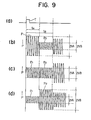
- the position information output P is proportional to the corresponding area of the flux- reversal areas 12 of the first and second position information Sl, S2 read by the head 3. Therefore, the variation in the position information output P corresponding to the positions 3a, 3b, 3c of the head 3, as shown in Figure 8 becomes as shown in Figures 9 (b) , 9(c), 9(d).
- the head 3b is affected by the equivalent influence from the flux-reversal areas 12a of the first position information Sl and the flux- reversal areas 12b of the second position information S2.
- the outputs Pl and P2 become of equal value, and the output P becomes constant.
- the head 3 is disposed at the position 3b displaced toward the adjacent n + 1 track side to the n track, the head 3 is more strongly affected by the influence from the flux-reversal areas 12a.
- the output Pl becomes larger than the output P2.
- the output P2 becomes larger than the output Pl.
- the position of the head to the n track can be discriminated by observing the magnitudes of the outputs Pl and P2.
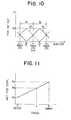
- the characteristic shown in Figure 10 can be described as below.
- the position displacement X can be represented by
- the equation (6) indicates that, when the track pitch kP is known, the displacing direction and the amount of position displacement from the center of the track of the head 3 can be calculated by using the position information outputs Va, Vb.
- the position of the head can be detected to be displaced by 25 microns toward the n + 1 track.
- the relationship between the displacing direction and the polarity of X is inverted for every track, but it may be readily discriminated whether the track number is even or odd, as the track pitch kP is generally known.
- equation (6) is evaluated with the position information output voltages Va, Vb by the control device 17, the position displacement of the head 3 can be calculated.
- the control device 17 can further compensate for the position displacement of the head 3 that is detected as described above so that the said displacement approximately become zero.
- the stopping angle of the stepping motor is generally determined by the combination of the excitation phases. It is known that, when the current values supplied to the phases are varied, the stopping angle can be finely controlled. This is called a microstep or a vernier drive. According to the invention, the position displacement of the head 3 can be compensated by finely varying the stopping angle of the stepping motor 5, by altering the interphase current of the motor 5 as result of changing the input of the D/A converter 18 by means of the control device 17. Another embodiment of the invention is now described by referring to Figure 12. In this case the position information is provided only in the inner and outer most tracks (10 c .10 c+n-1' .... indicating the center of the respective tracks).
- the position displacements of the inner and outer most tracks are detected and memorized on the basis of the position information provided on the inner and outer most tracks.
- the circuit of Figure 5 block 17 presumed position displacement output means 17p is provided, and when the power is turned on the head is moved by the operating means to the inner most or outer most track, the amount of position displacement is memorized by the above presumed position displacement output means and further the amount of position displacement is made and memorized by presumed position displacement output means 17p as shown in Figure 11.
- the presumed position displacement outputting means for presuming the position displacement of the positioning track by linear approximation of the characteristic shown in Figure 11 from the detected values is provided, and when positioning the head on a predetermined track, the head can be repositionedd in advance to the presumed position displacement by compensating for the presumed position displacement. According to this method, the time period required for compensation can be shortened.
- the system detects the displacement for the inner most and outer most tracks at regular intervals. Each time the system scans the position information on the inner most and outer most tracks, it recalculates the presumed position displacements for the intermediate tracks.
- control device 8 and the control device 17 are separately provided. However, these devices may be summarized in a microcomputer.
- the magnetic disk apparatus driven by the stepping motor has been described.
- the invention may also be applied to a magnetic disk device driven by a voice coil, an optical disk device or a laser disk apparatus.
- the configuration according to the positioning control device, of the magnetic head of the present invention provides a method for applying positioning information to a part of the data tracks and compensating the positioning of the head for environmental change. Therefore, the relative position displacement between the data track and the magnetic head due to the variation in the environmental temperature can be minimized, thereby improving the systems reliability.
- a head and a disk are now described in case of a magnetic head and a magnetic disk, respectively.
- Figure 13 shows the area of the magnetic disk surface.
- numeral 10 designates data track areas of concentric tracks for memorizing data.
- Numeral 27 designates guard band areas formed on the outside of the data track areas, and which comprises the areas 27a, 27b.
- O designates an index position corresponding to an index timing signal T outputted once per one revolution of a spindle motor.
- Numeral 11 designates a read-only position information area written in advance on a part of the data track areas 10 and the guard band areas 27, starting from the index position 0.
- Figure 14 is an enlarged view showing the essential portion of the position information areas 11 in Figure 13.
- numerals 30a and 30b designate flux-reversal areas which are provided correspodning to the data tracks.
- Numeral 31 designates non-flux-reversal areas.
- the position information areas 11, the flux-reversal areas, are distinctly indicated from other areas by hatched lines.
- two flux-reversal areas 30a, 30b are arranged at both sides of the nonflux reversal area equally to the interval of the each data track so as not to be adjacemtn to each other in a manner socalled "checkerwise pattern shape".
- the areas 30a are disposed in the vicinity of the index position O,and the areas 30b are disposed remotely from the index position in such a manner that the areas 30a, 30b are radially displaced by half pitch of the interval of the data track.
- one fluxreversal area 30c is recorded, and a non-flux- reveral area is recorded remotely therefrom in the vicinity of the index position 0.
- This area 27a extends towards the outer diameter of the disk, away from track 0. Both the areas are formed in the outer peripheral direction from the center of the track 0.
- one flux-reversal area 30d is recorded remotely from the index position O, and the non-flux-reversal area is recorded in the vicinity of the index position. Both the areas are formed toward the inner peripheral direction from the center of the track N.
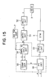
- Figure 15 is a block diagram of a circuit for detecting track 0 on the basis of the position information of 11 recorded on the magnetic disk surface.
- numeral 32 designates a rectifier circuit (RECT CKT) for rectifying a signal F ready by the head 3.
- Numeral 33 designates a smoothing circuit (SMTH CKT) for smoothing the signal rectified by the rectifier 32.
- Numeral 34 designates a signal smaple and hold circuit (SMPL & HOLD) for sampling and holding a smoothed signal H output by the smoothing circuit 33 at a predetermined time with respect to the index timing signal T from an index timing sensor 7 sent once per every one revolution of the spindle motor as a reference timing signal.
- SMPL & HOLD signal smaple and hold circuit
- Numeral 35 designates a comparator circuit (COMP CKT) for comparing two signals I and J which are held in a holding circuit 34 at a timing t on the basis of the index timing signal T and outputting any value of -, 0, + of a comparison output signal K to a positioning control circuit (PC CKT) 36 according to the position corresponding to the track 0 of the head.
- the control circuit 36 for detecting track 0 outputs a control signal L to a drive circuit 22 (DRVE CKT) for driving a stepping motor 5 for positioning the head 3.
- the operation is described by referring to the signal waveform diagram of Figure 16.
- the signal waveform diagrams of Figures 16(a), 16(b), 16(c) indicate the signals of the position information areas which are read from the head 3, when the head 3 is positioned on the guard band area 27b on the inner peripheral when the head 3 is positioned on the center line of the track 0 (lOa), and when the head 3 is positioned on the guard band area 27a on the outer peripheral respectively.
- the positions of the head 3 thereof are as shown by 3a, 3b, 3c in Figures 14, respectively. In the case that the head 3 is positioned to 3a, 3b, 3c, the displays in Fig.
- FIG. 16 depict a magnetic head read signal R, a rectified signal U and a smoothed signal W read in the position information area 11 using the index timing signal T as a reference timing signal, a holding signal I sampled at a time t A ', and a holding signal J sampled at a time t B ' and a comparison output signal k, respectively.
- the range 0 to t A indicates the period of time for reading the fluxreversal 30a, 30c near the index position of the position information area of the disk 1
- the range t A to t B indicates the period of time for reading from the flux-reversal areas 30b, 30d remote from the index position 0.
- the signal K is outputted as any one the following signals -, 0 or +. These occur when the head 3 is disposed in the guard band area 27b at the inner peripheral side of the disk 1 (3a in Figure 14), when the head 3 is disposed on the track 10 (3b in Figure 14), or when the head 3 is disposed on the guard band area 27b at the outer peripheral side (3c in Figure 14), respectively.
- the head 3 position can be determined by the position information of the position information areas 11 recorded on the disk 1 whether the head 3 is disposed on the guard band area 27b at the inner peripheral side of the disk 1, on the track area 10 or on the guard band area 27a at the outer peripheral side.
- the head 3 To detect a track 0 (10a in Figure 14), the head 3 is once positioned on the guard band area 27a on the outer peripheral, the head 3 is then moved to the inner peripheral while detecting the comparison output signal K, and the change from + to 0 of the comparison output signal K is detected, which results in an output of the track 0 signal Z in the positioning control circuit 36 which inputs the comparison output signal K. In other words, when the change from + to 0 of the comparison output signal K is detected, it is allowed to output a track 0 signal Z which indicates that the positioning operation is complete. Using by the positioning control circuit 36 and the change from + to 0 of the comparison output signal K, the head 3 can be positioned on track 0.
- the fact that the head 3 is correctly positioned on track 0 may be confirmed by performing an operation similar to the original positioning procedure. It can be confirmed that the head is on track 0 by displacing the head and observing the output to confirm either the presence of the guard band 27a or 27b or track positioning information 12, 13.
- track 0 is the outer peripheral of the disk 1 recorded on.
- track 0 is recoreded on the inner peripheral, a similar operation can be performed and the same effect may be attained.
- the present invention may be applied to a magnetic disk apparatus driven by a voice coil, or an optical disk device or a laser disk device.
- the position information areas are provided on a part of the data track of the magnetic disk, and the track 0 can be detected by the positioning control device that makes use of the position information. Therefore, a mechanical external sensor may be eliminated.
- This invention provides the magnetic disk device having high accuracy thereby.
Landscapes
- Moving Of The Head To Find And Align With The Track (AREA)
Abstract
Description
- This invention relates to a positioning control device of a head. More particularly, it relates to positioning a head to a data track of a disk such as a magnetic disk device or an optical disk device and the likes.
- In the below, a conventional magnetic head and a prior-art magnetic disk device are described in detail by way of examples in case of a head and a disk device as claimed.
- Heretofore, a prior-art magnetic disk device of a memory used, for example, in a computer and the likes is configured as shown in Fig. 1. In Fig. 1,
numeral 1 designates a magnetic disk, and information is recorded on tracks arranged concentrically at a predetermined interval. Numeral 2 designates a spindle motor for rotating thedisk 1 at a predetermined speed. Numeral 3 designates a magnetic head for reading/writing informatibn in the tracks of thedisk 1. Numeral 4 designates an actuator for moving thehead 3 by the drive force of a positioning stepping motor 5 (STM) to position thehead 3 on an arbitrary track. Numeral 6 designates a base for fastening themotor 2, theactuator 4 and themotor 5. Numeral 7pA designates an index sensor for detecting the index of the rotating section of themotor 2 and outputting an index signal per one revolution. - The circuit arrangement of the magnetic disk device thus configurated as described above is now described by referring to Fig. 2.
- In Fig. 2,
numeral 8 designates a positioning control device (PCD) for outputting a drive signal B for rotating themotor 5 when receiving a head movement command signal A from a controller and outputting a positioning completion signal Z when thehead 3 is completely moved to the track position to be positioned. Numeral 9 designates a driving amplifier device (DAD) for amplifying the drive signal B, rotating themotor 5 by the drive power D and setting the stopping angle of the motor. Thus, thehead 3 is positioned on the track of thedisk 1. When the index sensor detects an index and the index detection signal is received by an external circuit (not shown), the head can read/write information on the corresponding track of thedisk 1. - Environmental temperature varies and since the temperature expansion coefficients and the likes of the
disk 1, theactuator 4 and the base 6 of the positioning control device of the prior-art disk apparatus are different from each other, the track on thedisk 1 is relatively displaced from the position of the positionedhead 3, an interference between the magnetisms produced by the adjacent tracks occurs, and the reliability in reading/writing information on the tracks by the head is deteriorated. Such a problem creates difficulties when a defect for increasing the density of the track to increase the total number of tracks on the disk. - An object of this invention is to eliminate the above-mentioned disadvantages inherent in the prior-art disk device, and a further object is to provide a disk device which can compensate when positioning a magnetic head by using position information read from the head after positioning the head. Thus being achieved by writing position information for setting the head at a position normal to the radial direction of the data tracks of the head on a part of the data track.
- Another object of this invention is to provide a magnetic disk device which can accurately detect a
track 0 as a reference track by using the position information by writing in advance the position information on a part of the tracks on the magnetic disk surface and controlling the position of the magnetic head to read the information from the magnetic disk. - Still another object of the invention is provide an index timing sensor having functions as a reference for timing for detecting the position information, and for indicating a reference for starting to operate factors (e.g., position information outputs VA, VB) to calculate the amount of positional displacement in addition to the function of the prior art index sensor which is used only to detect the index and to indicate the starting time for reading/writi data.
-
- Figure 1 is a mechanical view showing a prior-art magnetic disk device;
- Figure 2 is a block diagram showing a positioning control device of a magnetic head in a prior-art magnetic disk device;
- Figure 3 is a view showing the configuration of an embodiment of a magnetic disk in accordance with the present invention;
- Figure 4 is a view showing the configuration of position information areas;
- Figure 5 is a block diagram showing another embodiment of a positioning control device of a magnetic disk device according to the present invention;
- Figure 6 is a waveform diagram showing the varied state of the position information output to a time;
- Figure 7(a) through 7(c) are waveform diagrams showing waveforms of processed rectified outputs;
- Figure 8 is a view showing the position displaced state of the magnetic head;
- Figures 9 and 10 are waveform diagrams showing the states of varied position information outputs to the position of the magnetic head;
- Figure 11 is a graph showing the characteristic for presuming the amount of the displaced positions of the tracks from the displaced position of the inner and outer tracks according to still another embodiment of the present invention; ,
- Figure 12 is a view of the configuration showing the position information areas of the case that the both end sides are most inner and outer sides in accordance with the embodiment shown in Figure 11;
- Figure 13 is a view showing the configuration of a magnetic disk surface of the magnetic disk device according to still another embodiment of the present invention;
- Figure 14 is an enlarged view showing the position information areas of the magnetic disk surface shown in Figure 13;
- Figure 15 is a block diagram of a magnetic disk device in accordance with still another embodiment of the present invention; and
- Figure 16 is a signal waveform diagram showing thereas output of the magnetic head position and the position information for describing the principle of the operation of the present invention.
- Figures 3 through 5 illustrate an embodiment of a positioning control device of a magnetic head in accordance with the present invention, wherein the same symbols in Figures 1 and 2 denote the same parts. In Figures 3 to 5,
numeral 10 designates data tracks, which are formed concentrically on amagnetic disk 1 for recording/regenerating data, and formed as 10a through 10e as shown in Figure 4. Numeral 11 designates position information areas including position information S started from the index (IDX)position 0. The position information S has the first position information area Sl and second position information area S2 obtained by alternatively disposing flux-reversal areas 12 and non-flux-reversal areas 13 radially and laterally in parallel as shown in Figure 4. In this case, while the flux-reversal areas 12 of the first position information Sl correspond to the non-flux-reversal areas 13 of the second position information S2, theareas data tracks 10a to 10e, but are displaced by half pitch to the data tracks. In Figure 5,numeral 14 designates a rectifier (RECT) for outputting an output E produced by rectifying the position information outputted from thehead 3,Numeral 15 designates an integrator (INTG) for integrating the rectified output E and outputting an amplitude F of the position information.Numeral 16 designates an analog digital converter (A/D) for digitizing the amplitude F and outputting the digitized positioninformation G. Numeral 17 designates a control device for compensating position displacement (CDC) for detecting the position displacement from the position information G and outputting a position compensating output H. Note that block 17p is relevant to the embodiment shown in Figs. 11-12. Numeral 18 designates a digital analog converter (D/A) for analogously converting an electric current supplied to thestepping motor 5 by the position compensating output H. An index timing signal T outputted from an index timing sensor (IDX TM SNR) 7 provides the start timing of the position information area 11 to thecontrol device 17. - The operation of the positioning control device of a magnetic head configurated as described above is now described by referring to the characteristic diagrams of Figures 4 to 9. Assume that the
disk 1 rotates in a direction by an arrow M. When a head movement command signal A is received from a controller, the head is not disposed on the track. Namely, it is not accordingly necesaary to compensate the position displacement of the head. This signal A is converted into the drive signal B including no position compensation of themotor 5 through thecontrol device 17 and the D/A converter 18. When the signal A is fed to the motor, the head is moved to the arbitrary track through the actuator by the rotation of the positioning device. The position compensation may then be executed. The compensation sequence is now described. The index timing signal T is outputted once from the index timing sensor 7 whenever thedisk 1 is rotated by one revolution. The position information output P is outputted from thehead 3. The position information output P has, as shown in Figure 6, a voltage output Pl (2VA) corresponding to the first position information Sl and a voltage output P2 (2VB) corresponding to the second position information S2, fed to therectifier 14, in which the voltage outputs Pl and P2 respectively become voltage outputs corresponding to times t and tB from the index timing signal T. The time t is an arrival time of thehead 3 from the start point Sl of the first position information Sl to the end point Sm, and the time t is an arrival time of the had 3 from the start point Sl of the first position information Sl to the end point Sn of the second position information S2. The voltages VA and VB are the maximum and the minimum amplitude output voltages of thehead 3, respectively. The position information output P is processed, as shown in Figure 7(a) and 7(b), by therectifier 14 and theintegrator 15, and further digitally converted by the A/D converter 16. Thecontrol device 17 samples the digitally converted position information output during each period of the times t from the index timing signal of 0 < t < tA and tA < t < tB as input thereof sequentially. - On the other hand, the position information output P is proportional to the corresponding area of the flux-
reversal areas 12 of the first and second position information Sl, S2 read by thehead 3. Therefore, the variation in the position information output P corresponding to thepositions head 3, as shown in Figure 8 becomes as shown in Figures 9 (b) , 9(c), 9(d). As is apparent from the Figure 9, when thehead 3 is accurately positioned at theposition 3b to the center of the n'th track, thehead 3b is affected by the equivalent influence from the flux-reversal areas 12a of the first position information Sl and the flux-reversal areas 12b of the second position information S2. Thus, as shown in Figure 9(c), the outputs Pl and P2 become of equal value, and the output P becomes constant. On the other hand, when thehead 3 is disposed at theposition 3b displaced toward the adjacent n + 1 track side to the n track, thehead 3 is more strongly affected by the influence from the flux-reversal areas 12a. Thus, as shown in Figure 9(b), the output Pl becomes larger than the output P2. When thehead 3 is disposed at theposition 3c displaced toward the adjacent n - 1 track side to the n track, thehead 3 is more strongly affected by the influence of the flux-reversal areas 12b. Thus, as shown in Figure 9(d), the output P2 becomes larger than the output Pl. The position of the head to the n track can be discriminated by observing the magnitudes of the outputs Pl and P2. - If the amount of position displacement from the center of the track is indicated by X, the track pitch (the distance between the tracks) is indicated by 1P, the maximum output voltage is indicated by Vo, the output voltage corresponding to the first position information Sl of the head is indicated by Va, and the output voltage corresponding to the second position information S2 is indicated by Vb, the characteristic shown in Figure 10 can be described as below.
- For Figure 10, in the range of -lP/2 < X < lP/2,


- From the equations (1) and (2),


- On the other hand, the value of Va + Vb becomes from the equations (1) and (2)

- When the equation (5) is substituted into equation (4), the position displacement X can be represented by

head 3 can be calculated by using the position information outputs Va, Vb. - For example, assuming that the track pitch lP = 100 microns, the output voltage Va = 3V and the output voltage Vb = 1V, from equation (6),

control device 17, the position displacement of thehead 3 can be calculated. - The
control device 17 can further compensate for the position displacement of thehead 3 that is detected as described above so that the said displacement approximately become zero. - The stopping angle of the stepping motor is generally determined by the combination of the excitation phases. It is known that, when the current values supplied to the phases are varied, the stopping angle can be finely controlled. This is called a microstep or a vernier drive. According to the invention, the position displacement of the
head 3 can be compensated by finely varying the stopping angle of the steppingmotor 5, by altering the interphase current of themotor 5 as result of changing the input of the D/A converter 18 by means of thecontrol device 17. Another embodiment of the invention is now described by referring to Figure 12. In this case the position information is provided only in the inner and outer most tracks (10c.10c+n-1' .... indicating the center of the respective tracks). In other words, the position displacements of the inner and outer most tracks are detected and memorized on the basis of the position information provided on the inner and outer most tracks. In this embodiment, in the circuit of Figure 5block 17 presumed position displacement output means 17p is provided, and when the power is turned on the head is moved by the operating means to the inner most or outer most track, the amount of position displacement is memorized by the above presumed position displacement output means and further the amount of position displacement is made and memorized by presumed position displacement output means 17p as shown in Figure 11. (This embodiment can be thought of to include 17p) It is noted that the presumed position displacement outputting means for presuming the position displacement of the positioning track by linear approximation of the characteristic shown in Figure 11 from the detected values is provided, and when positioning the head on a predetermined track, the head can be repositionedd in advance to the presumed position displacement by compensating for the presumed position displacement. According to this method, the time period required for compensation can be shortened. - The system detects the displacement for the inner most and outer most tracks at regular intervals. Each time the system scans the position information on the inner most and outer most tracks, it recalculates the presumed position displacements for the intermediate tracks.
- In the embodiments described above, the
control device 8 and thecontrol device 17 are separately provided. However, these devices may be summarized in a microcomputer. - In the embodiments described above, the magnetic disk apparatus driven by the stepping motor has been described. However, the invention may also be applied to a magnetic disk device driven by a voice coil, an optical disk device or a laser disk apparatus.
- From the foregone description it is seen that the configuration according to the positioning control device, of the magnetic head of the present invention, as described above, provides a method for applying positioning information to a part of the data tracks and compensating the positioning of the head for environmental change. Therefore, the relative position displacement between the data track and the magnetic head due to the variation in the environmental temperature can be minimized, thereby improving the systems reliability.
- Furthermore, high track density can be achieved at lower cost.
- Then, still another embodiment of the invention is now described by referring to figs. 13 through 16. In Figures 13 to 16, the same symbols in Figures 1 through 12 denote the same parts.
- A head and a disk are now described in case of a magnetic head and a magnetic disk, respectively.
- Figure 13 shows the area of the magnetic disk surface. In Figure 13, numeral 10 designates data track areas of concentric tracks for memorizing data. Numeral 27 designates guard band areas formed on the outside of the data track areas, and which comprises the
areas data track areas 10 and the guard band areas 27, starting from theindex position 0. Figure 14 is an enlarged view showing the essential portion of the position information areas 11 in Figure 13. In Figure 14,numerals Numeral 31 designates non-flux-reversal areas. The position information areas 11, the flux-reversal areas, are distinctly indicated from other areas by hatched lines. In the position information areas in thedata track areas 10, two flux-reversal areas areas 30a are disposed in the vicinity of the index position O,and theareas 30b are disposed remotely from the index position in such a manner that theareas guard bands fluxreversal area 30c is recorded, and a non-flux- reveral area is recorded remotely therefrom in the vicinity of theindex position 0. Thisarea 27a extends towards the outer diameter of the disk, away fromtrack 0. Both the areas are formed in the outer peripheral direction from the center of thetrack 0. In the position information area of theguard band area 27b towards the inside of track N, one flux-reversal area 30d is recorded remotely from the index position O, and the non-flux-reversal area is recorded in the vicinity of the index position. Both the areas are formed toward the inner peripheral direction from the center of the track N. Figure 15 is a block diagram of a circuit for detectingtrack 0 on the basis of the position information of 11 recorded on the magnetic disk surface. In Figure 15, numeral 32 designates a rectifier circuit (RECT CKT) for rectifying a signal F ready by thehead 3.Numeral 33 designates a smoothing circuit (SMTH CKT) for smoothing the signal rectified by therectifier 32.Numeral 34 designates a signal smaple and hold circuit (SMPL & HOLD) for sampling and holding a smoothed signal H output by the smoothingcircuit 33 at a predetermined time with respect to the index timing signal T from an index timing sensor 7 sent once per every one revolution of the spindle motor as a reference timing signal. Numeral 35 designates a comparator circuit (COMP CKT) for comparing two signals I and J which are held in a holdingcircuit 34 at a timing t on the basis of the index timing signal T and outputting any value of -, 0, + of a comparison output signal K to a positioning control circuit (PC CKT) 36 according to the position corresponding to thetrack 0 of the head. Thecontrol circuit 36 for detectingtrack 0 outputs a control signal L to a drive circuit 22 (DRVE CKT) for driving a steppingmotor 5 for positioning thehead 3. - The operation is described by referring to the signal waveform diagram of Figure 16. The signal waveform diagrams of Figures 16(a), 16(b), 16(c) indicate the signals of the position information areas which are read from the
head 3, when thehead 3 is positioned on theguard band area 27b on the inner peripheral when thehead 3 is positioned on the center line of the track 0 (lOa), and when thehead 3 is positioned on theguard band area 27a on the outer peripheral respectively. The positions of thehead 3 thereof are as shown by 3a, 3b, 3c in Figures 14, respectively. In the case that thehead 3 is positioned to 3a, 3b, 3c, the displays in Fig. 16 depict a magnetic head read signal R, a rectified signal U and a smoothed signal W read in the position information area 11 using the index timing signal T as a reference timing signal, a holding signal I sampled at a time tA', and a holding signal J sampled at a time tB' and a comparison output signal k, respectively. The time t which constitutes the time base of the method uses as a reference at this time the signal output time by the index timing signal T at t = 0. Therange 0 to tA indicates the period of time for reading thefluxreversal disk 1, and the range tA to tB indicates the period of time for reading from the flux-reversal areas index position 0. In Figure 16, t = tA' and t = tB' are sampling times for sampling and holding the smoothed signal W by the holdingcircuit 34. t = tB' is also the period of time for operating the comparator 35. - When the comparison output signal K as the output of the comparator 35 is observed, the signal K is outputted as any one the following signals -, 0 or +. These occur when the
head 3 is disposed in theguard band area 27b at the inner peripheral side of the disk 1 (3a in Figure 14), when thehead 3 is disposed on the track 10 (3b in Figure 14), or when thehead 3 is disposed on theguard band area 27b at the outer peripheral side (3c in Figure 14), respectively. In other words, when the comparison output signal K as the output signal of the comparator 35 is known, thehead 3 position can be determined by the position information of the position information areas 11 recorded on thedisk 1 whether thehead 3 is disposed on theguard band area 27b at the inner peripheral side of thedisk 1, on thetrack area 10 or on theguard band area 27a at the outer peripheral side. - To detect a track 0 (10a in Figure 14), the
head 3 is once positioned on theguard band area 27a on the outer peripheral, thehead 3 is then moved to the inner peripheral while detecting the comparison output signal K, and the change from + to 0 of the comparison output signal K is detected, which results in an output of thetrack 0 signal Z in thepositioning control circuit 36 which inputs the comparison output signal K. In other words, when the change from + to 0 of the comparison output signal K is detected, it is allowed to output atrack 0 signal Z which indicates that the positioning operation is complete. Using by thepositioning control circuit 36 and the change from + to 0 of the comparison output signal K, thehead 3 can be positioned ontrack 0. The fact that thehead 3 is correctly positioned ontrack 0 may be confirmed by performing an operation similar to the original positioning procedure. It can be confirmed that the head is ontrack 0 by displacing the head and observing the output to confirm either the presence of theguard band positioning information - As described above,
track 0 is the outer peripheral of thedisk 1 recorded on. However, even when thetrack 0 is recoreded on the inner peripheral, a similar operation can be performed and the same effect may be attained. - As described above, although a magnetic disk device driven by a stepping motor has been described, the present invention may be applied to a magnetic disk apparatus driven by a voice coil, or an optical disk device or a laser disk device.
- According to the present invention as described above, the position information areas are provided on a part of the data track of the magnetic disk, and the
track 0 can be detected by the positioning control device that makes use of the position information. Therefore, a mechanical external sensor may be eliminated. This invention provides the magnetic disk device having high accuracy thereby.
Claims (12)
characterised in that position information (S1,S2) provided over a predetermined radial area (11) of the disk (1) and has a pattern such as to generate different information according to the position of the head relative to the centre line of the selected track,
and in that position compensating means (14-18) are provided, for compensating any displacement of the head from the data track centre line, comprising means for detecting the position information and generating a corresponding signal which indicates at least the diretion of any such displacement, and means responsive to the said signal, for adjusting the head transversely to the track centre line so as to compensate the displacement.
and in that compensating means are provided, for compensating any displacement of the head from the centre line of any selected track, comprising means for detecting the position information from the said predetermined tracks, means responsive to this information for determining whether the head position driven by the position control means (8) is displaced from the track centre lines, means for calculating therefrom a corresponding presumed head/centreline displacement for the other tracks in particular intermediate tracks, and means for compensating the head position driven by the control means (8) to eliminate the presumed head displacement for any selected track.
Applications Claiming Priority (4)
| Application Number | Priority Date | Filing Date | Title |
|---|---|---|---|
| JP221484/83 | 1983-11-25 | ||
| JP58221484A JPS60113370A (en) | 1983-11-25 | 1983-11-25 | Position controller of recording and regeneration element |
| JP17155384A JPS6150259A (en) | 1984-08-20 | 1984-08-20 | Magnetic disc device |
| JP171553/84 | 1984-08-20 |
Publications (3)
| Publication Number | Publication Date |
|---|---|
| EP0154085A2 true EP0154085A2 (en) | 1985-09-11 |
| EP0154085A3 EP0154085A3 (en) | 1987-03-25 |
| EP0154085B1 EP0154085B1 (en) | 1990-07-04 |
Family
ID=26494243
Family Applications (1)
| Application Number | Title | Priority Date | Filing Date |
|---|---|---|---|
| EP19840308193 Expired EP0154085B1 (en) | 1983-11-25 | 1984-11-26 | Head positioning apparatus for a magnetic disc device |
Country Status (5)
| Country | Link |
|---|---|
| EP (1) | EP0154085B1 (en) |
| DE (1) | DE3482655D1 (en) |
| FI (1) | FI88973C (en) |
| HK (1) | HK13293A (en) |
| SG (1) | SG96592G (en) |
Cited By (9)
| Publication number | Priority date | Publication date | Assignee | Title |
|---|---|---|---|---|
| DE3716971A1 (en) * | 1986-06-04 | 1987-12-10 | Alps Electric Co Ltd | DISK DRIVE WITH DEVICE AND METHOD FOR CONTROLLING THE HEAD POSITIONING |
| EP0227061A3 (en) * | 1985-12-19 | 1988-10-12 | Victor Company Of Japan, Limited | Disk drive apparatus providing increased track density |
| US4860131A (en) * | 1986-09-08 | 1989-08-22 | Alps Electric Co., Ltd. | Method for recorrecting head position in a disk drive |
| US4876618A (en) * | 1986-11-22 | 1989-10-24 | Alps Electric Co., Ltd. | Method for detecting zero track |
| US4884152A (en) * | 1986-06-04 | 1989-11-28 | Alps Electric Co., Ltd. | Method for restoring track 0 |
| EP0314879A3 (en) * | 1987-07-15 | 1990-03-14 | Nec Corporation | Control of relative position between a magnetic head and a recording medium |
| EP0335546A3 (en) * | 1988-03-28 | 1990-11-22 | Seagate Technology International | Off-set nulling system and method for computer disk drives |
| EP0241868A3 (en) * | 1986-04-16 | 1992-02-12 | Hitachi, Ltd. | Disk apparatus |
| EP0492774A3 (en) * | 1990-12-21 | 1993-03-24 | Fujitsu Limited | Method and system for correcting offset of head position signal |
Family Cites Families (2)
| Publication number | Priority date | Publication date | Assignee | Title |
|---|---|---|---|---|
| US3534344A (en) * | 1967-12-21 | 1970-10-13 | Ibm | Method and apparatus for recording and detecting information |
| US4390912A (en) * | 1980-11-12 | 1983-06-28 | Digital Equipment Corporation | Transducer positioning system and data disk therefor |
-
1984
- 1984-11-23 FI FI844612A patent/FI88973C/en not_active IP Right Cessation
- 1984-11-26 EP EP19840308193 patent/EP0154085B1/en not_active Expired
- 1984-11-26 DE DE8484308193T patent/DE3482655D1/en not_active Expired - Lifetime
-
1992
- 1992-09-26 SG SG96592A patent/SG96592G/en unknown
-
1993
- 1993-02-18 HK HK13293A patent/HK13293A/en unknown
Cited By (10)
| Publication number | Priority date | Publication date | Assignee | Title |
|---|---|---|---|---|
| EP0227061A3 (en) * | 1985-12-19 | 1988-10-12 | Victor Company Of Japan, Limited | Disk drive apparatus providing increased track density |
| EP0241868A3 (en) * | 1986-04-16 | 1992-02-12 | Hitachi, Ltd. | Disk apparatus |
| DE3716971A1 (en) * | 1986-06-04 | 1987-12-10 | Alps Electric Co Ltd | DISK DRIVE WITH DEVICE AND METHOD FOR CONTROLLING THE HEAD POSITIONING |
| US4884152A (en) * | 1986-06-04 | 1989-11-28 | Alps Electric Co., Ltd. | Method for restoring track 0 |
| US4860131A (en) * | 1986-09-08 | 1989-08-22 | Alps Electric Co., Ltd. | Method for recorrecting head position in a disk drive |
| US4876618A (en) * | 1986-11-22 | 1989-10-24 | Alps Electric Co., Ltd. | Method for detecting zero track |
| EP0314879A3 (en) * | 1987-07-15 | 1990-03-14 | Nec Corporation | Control of relative position between a magnetic head and a recording medium |
| EP0335546A3 (en) * | 1988-03-28 | 1990-11-22 | Seagate Technology International | Off-set nulling system and method for computer disk drives |
| EP0492774A3 (en) * | 1990-12-21 | 1993-03-24 | Fujitsu Limited | Method and system for correcting offset of head position signal |
| US5457587A (en) * | 1990-12-21 | 1995-10-10 | Fujitsu Limited | Method and system for correcting offset of head position signal |
Also Published As
| Publication number | Publication date |
|---|---|
| EP0154085A3 (en) | 1987-03-25 |
| FI844612L (en) | 1985-05-26 |
| EP0154085B1 (en) | 1990-07-04 |
| DE3482655D1 (en) | 1990-08-09 |
| FI88973B (en) | 1993-04-15 |
| SG96592G (en) | 1993-01-29 |
| FI88973C (en) | 1993-07-26 |
| HK13293A (en) | 1993-02-26 |
| FI844612A0 (en) | 1984-11-23 |
Similar Documents
| Publication | Publication Date | Title |
|---|---|---|
| EP0471314B1 (en) | Edge servo for disk drive head positioner | |
| US4912576A (en) | Method for writing a servo pattern | |
| US4782404A (en) | Positioning system for a disc drive using a stepper motor | |
| US4476503A (en) | Method for the recognition of an edge of a magnetic medium and a device for implementation of the method | |
| US4499511A (en) | System for detecting position of a read-write head in seek operation on a disk memory having data servo spectors | |
| EP0420439A1 (en) | Method of and apparatus for determining the position of a transducer | |
| US4700244A (en) | Process and system for compensating for information shifts on disc storage media | |
| EP0154085A2 (en) | Head positioning apparatus for a magnetic disc device | |
| EP0031500A2 (en) | Servo system for centering a transducer over a path | |
| EP0273546B1 (en) | Servo system for a disk drive | |
| KR940000636B1 (en) | Method and arrangement for detecting error signals in a disk drive, and a magnetic test disk therefor | |
| US5659438A (en) | Head positioning control system using stored voice coil motor correction data | |
| EP0321942A2 (en) | Servo pattern for a flexible magnetic disk | |
| EP0447460B1 (en) | Dual reference track scheme | |
| US5079654A (en) | Data transducer position control system for data transfer apparatus employing dislike record media | |
| US7751143B2 (en) | Head position control method, head position control device, and magnetic recording evaluation apparatus | |
| US5566034A (en) | Off-track detection with charge redistribution A/D circuits | |
| US4510537A (en) | Magnetic head moving velocity detector | |
| US6356519B1 (en) | Disk apparatus for moving head to center of target track in seek operation | |
| GB2184869A (en) | Tracking magnetic discs | |
| EP0324962A2 (en) | Process for optimizing head position to overcome disk misclamping and imperfections | |
| US5241431A (en) | Apparatus for adjustment of position slope for servo | |
| US20040150906A1 (en) | Servo writing method, servo writer, and program thereof | |
| EP0484907A2 (en) | Magnetic head positioning scheme using a capacitive transducer | |
| WO1997015047A1 (en) | Disk drive servo system |
Legal Events
| Date | Code | Title | Description |
|---|---|---|---|
| PUAI | Public reference made under article 153(3) epc to a published international application that has entered the european phase |
Free format text: ORIGINAL CODE: 0009012 |
|
| AK | Designated contracting states |
Designated state(s): DE FR GB |
|
| PUAL | Search report despatched |
Free format text: ORIGINAL CODE: 0009013 |
|
| AK | Designated contracting states |
Kind code of ref document: A3 Designated state(s): DE FR GB |
|
| 17P | Request for examination filed |
Effective date: 19870430 |
|
| 17Q | First examination report despatched |
Effective date: 19880629 |
|
| GRAA | (expected) grant |
Free format text: ORIGINAL CODE: 0009210 |
|
| AK | Designated contracting states |
Kind code of ref document: B1 Designated state(s): DE FR GB |
|
| REF | Corresponds to: |
Ref document number: 3482655 Country of ref document: DE Date of ref document: 19900809 |
|
| REG | Reference to a national code |
Ref country code: GB Ref legal event code: 727 |
|
| REG | Reference to a national code |
Ref country code: GB Ref legal event code: 727A |
|
| ET | Fr: translation filed | ||
| REG | Reference to a national code |
Ref country code: GB Ref legal event code: 727B |
|
| REG | Reference to a national code |
Ref country code: GB Ref legal event code: SP |
|
| PLBE | No opposition filed within time limit |
Free format text: ORIGINAL CODE: 0009261 |
|
| STAA | Information on the status of an ep patent application or granted ep patent |
Free format text: STATUS: NO OPPOSITION FILED WITHIN TIME LIMIT |
|
| 26N | No opposition filed | ||
| PGFP | Annual fee paid to national office [announced via postgrant information from national office to epo] |
Ref country code: FR Payment date: 19931110 Year of fee payment: 10 |
|
| PGFP | Annual fee paid to national office [announced via postgrant information from national office to epo] |
Ref country code: GB Payment date: 19931116 Year of fee payment: 10 |
|
| PGFP | Annual fee paid to national office [announced via postgrant information from national office to epo] |
Ref country code: DE Payment date: 19931123 Year of fee payment: 10 |
|
| PG25 | Lapsed in a contracting state [announced via postgrant information from national office to epo] |
Ref country code: GB Effective date: 19941126 |
|
| GBPC | Gb: european patent ceased through non-payment of renewal fee |
Effective date: 19941126 |
|
| PG25 | Lapsed in a contracting state [announced via postgrant information from national office to epo] |
Ref country code: FR Effective date: 19950731 |
|
| PG25 | Lapsed in a contracting state [announced via postgrant information from national office to epo] |
Ref country code: DE Effective date: 19950801 |
|
| REG | Reference to a national code |
Ref country code: FR Ref legal event code: ST |