EP0153745B1 - Microwave discharge light source apparatus - Google Patents
Microwave discharge light source apparatus Download PDFInfo
- Publication number
- EP0153745B1 EP0153745B1 EP85102201A EP85102201A EP0153745B1 EP 0153745 B1 EP0153745 B1 EP 0153745B1 EP 85102201 A EP85102201 A EP 85102201A EP 85102201 A EP85102201 A EP 85102201A EP 0153745 B1 EP0153745 B1 EP 0153745B1
- Authority
- EP
- European Patent Office
- Prior art keywords
- light source
- source apparatus
- microwave
- discharge light
- microwave discharge
- Prior art date
- Legal status (The legal status is an assumption and is not a legal conclusion. Google has not performed a legal analysis and makes no representation as to the accuracy of the status listed.)
- Expired
Links
Images





Classifications
-
- H—ELECTRICITY
- H01—ELECTRIC ELEMENTS
- H01J—ELECTRIC DISCHARGE TUBES OR DISCHARGE LAMPS
- H01J65/00—Lamps without any electrode inside the vessel; Lamps with at least one main electrode outside the vessel
- H01J65/04—Lamps in which a gas filling is excited to luminesce by an external electromagnetic field or by external corpuscular radiation, e.g. for indicating plasma display panels
- H01J65/042—Lamps in which a gas filling is excited to luminesce by an external electromagnetic field or by external corpuscular radiation, e.g. for indicating plasma display panels by an external electromagnetic field
- H01J65/044—Lamps in which a gas filling is excited to luminesce by an external electromagnetic field or by external corpuscular radiation, e.g. for indicating plasma display panels by an external electromagnetic field the field being produced by a separate microwave unit
-
- H—ELECTRICITY
- H01—ELECTRIC ELEMENTS
- H01P—WAVEGUIDES; RESONATORS, LINES, OR OTHER DEVICES OF THE WAVEGUIDE TYPE
- H01P7/00—Resonators of the waveguide type
- H01P7/06—Cavity resonators
Definitions
- the present invention relates to a microwave discharge light source apparatus according to the precharacterizing clause of claim 1 (EP-A-0 035 898).
- a microwave discharge light source apparatus having a microwave resonance cavity having a cavity wall surface, a substantial part of which is constituted by a light transmitting member is known in publications such as Japanese Unexamined Utility Model Publication 168167/1982 ( Figure 1).
- the conventional apparatus as shown in Figure 1 is constructed in such a manner that microwaves radiated from a magnetron 1 are passed from a magnetron antenna 2 through a waveguide 3 and are fed into a microwave resonance cavity 5 through a power feeding port 8. Electric discharge of gas is caused in a lamp 9 by the microwaves. Light caused by luminescence of the gas is emitted outside through a metallic mesh 7. The emitted light is reflected by a light reflecting plate (not shown) and so on to shine a surface to be irradiated. In the microwave discharge light source apparatus having the above-mentioned construction, light emitted from the lamp 9 is almost radiated outside through the metallic mesh 7 directly.
- the conventional apparatus has disadvantages that since a mesh formed by knitting fine metallic wires (hereinbelow referred to as wires) as the metallic mesh 7 is usually used, the metallic mesh 7 may be broken due to over-heating by microwave loss which is caused by electrical contact resistance at crossing parts of the wires and efficiency of power feeding to the lamp 9 is poor, hence luminous efficiency is low. Further, the mesh is weak in mechanical strength. When an external force is applied to the mesh, the microwave resonance cavity 5 is deformed.
- EP 0 035 898 A1 discloses a microwave generated plasma light source apparatus with a light transmitting member covering the front opening of the cavity. The efficiency of this apparatus is poor, because more than 50% of light emitted outside from the cavity is reflected by the cavity wall resulting in losses. The distribution of light produced by said apparatus is substantially determined by the shape of the cavity wall.
- FIG. 2 shows an embodiment of the microwave discharge light source apparatus of the present invention.
- a reference numeral 4 designates a ventilating opening and a numeral 5 designates a cylindrical microwave resonance cavity.
- a light transmitting member 7 is constituted by an electrically continuous metallic mesh and so formed that the sum of three-dimensional angles formed by extension line extending from a point in a lamp 9 to the light transmitting member 7 is 2 ⁇ steradian or more.
- a power feeding port 8 is formed in a cavity wall 6 made of metal at a position to be connected to a waveguide 3 to feed microwaves from the waveguide 3 into the microwave resonance cavity 5.
- the lamp 9 is made of a light transmission substance such as quartz glass and contains a rare gas and mercury and so on.
- a lamp supporting member 91 made of a dielectric substance such as quartz glass extends from the outer wall of the lamp 9 and is fixed to the cavity wall 6 by means of a screw 10 so that the lamp 9 is secured to the cavity wall 6.
- a light reflecting plate 11 surrounds the microwave resonance cavity 5 to reflect light emitted from the cavity 5.
- a reference numeral 12 designates a cooling fan for cooling the magnetron 1 and the lamp 9 and numeral 13 designates a casing for covering the above-mentioned elements.
- Microwaves are excited at transmission mode from the magnetron 1 through the magnetron antenna 2 to the waveguide 3.
- the microwaves are fed to the microwave resonance cavity 5 surrounded by the cavity wall 6 and the metallic mesh 7 through the power feeding port 8.
- Rare gas contained in the lamp 9 is initiated to discharge by the microwaves and the lamp wall is heated by energy of the microwaves.
- the discharge of the gas causes evaporation of mercury and electric discharge of metallic gas such as mercury gas is mainly resulted.
- luminescence is resulted at absorption spectra depending on a kind of the metallic gas.
- the metallic mesh 7 functions to reflect the microwaves as metal do and allows light to pass through the openings of the mesh. Namely, the metallic mesh 7 functions as an opaque body for the microwaves and functions as a transparent body for light. Accordingly, light from the lamp 9 is emitted outside through the microwave resonance cavity 5 and reflected at the light reflecting plate 11.
- the reflecting plate 11 can be designed to have various shapes depending on how light is used. Since the light reflecting plate 11 is positioned outside of the microwave resonance cavity 5, design of the light reflecting plate is possible from the optical viewpoint without consideration of affect to microwave characteristics.
- the microwave power supplying method used in the above-mentioned embodiment is useful for radiating low grade resonance mode and the low grade resonance mode reduces the size of the microwave resonance cavity 5.
- Figure 3a is a longitudinal cross-sectional view showing a mode pattern of an embodiment of the cylindrical microwave resonance cavity of the present invention and Figure 3b is a transverse cross-sectional view taken along a line B-B in Figure 3a.
- Figure 3a shows in detail connection between transmission mode in the waveguide 3 and resonance mode in the microwave resonance cavity 5.
- solid lines and small circles E represent the lines of electric force, i.e. an electric field
- dotted lines H represent the lines of magnetic force i.e. a magnetic field.
- the mode in the waveguide 3 is a square TE10 mode and the mode in the microwave resonance cavity 5 is a cylindrical TE111 mode, namely, excitation of the microwaves is effected with modes in which there is a single projection of electromagnetic field in every direction.
- connection of the modes is easy because the directions of the electric field and the magnetic field in the waveguide 3 and the microwave resonance cavity 5 are coincident.
- the microwave resonance cavity 5 is so designed that resonance is caused under constant discharging condition of the metallic gas such as mercury in the lamp 9.
- a constant of the microwave of the lamp 9 varies depending on evaporation of the metallic gas until the discharge becomes normal after initiation of the discharge. On account of this, the microwaves are out of condition of resonance until reaching the normal condition.
- microwave energy necessary to evaporate metal can be supplied from the waveguide 3 to the microwave resonance cavity 5 to cause discharge of the lamp 9 without providing any means for changing the condition as the time goes, in the waveguide 3 or the microwave resonance cavity 5.
- the microwave resonance cavity 5 is small and a relatively strong microwave electromagnetic field is produced even though the microwave is out of the condition of resonance. Accordingly, energy can be supplied to the lamp 9 at the initiation of discharge whereby evaporation of metal quickly takes place and normal condition is obtainable for a short time.
- the waveguide 3 has a square shape in cross section of 95 mm x 54 mm
- the microwave resonance cavity 5 is of a cylindrical cavity having a diameter of 80 mm and a height of 90 mm
- the lamp 9 is of a spherical shape having a diameter of 30 mm, in which 7999.32 Pa (60 Torr) of argon and 100 mg of mercury are filled. It has been revealed that when microwaves of a frequency of 2450 MHz and power of 800 W, it takes about 5 seconds before reaching normal condition and coefficient of power reflection of the microwaves is 0.1 or below under the condition that matching of the waveguide and the microwave resonance cavity is normal.
- the light transmitting member 7 consisting of a metallic mesh used in the test is formed in such a manner that stainless steel sheet of 0.1 mm thick is subjected to etching to form it in a lattice form in which the pitch of lattice is 1 mm and the width of wire is 0.1 mm.
- the wires In the conventional mesh formed by knitting thin metal wires, the wires have contact points, namely they are electrically connected through contact resistors.
- the metallic mesh formed in accordance with the embodiment is electrically continuous. Accordingly, loss in a wall surface current flowing in the inner wall of the microwave resonance cavity 5 is small, whereby the metallic mesh is not heated by the microwaves, hence the lamp 9 is supplied with power to increase efficiency of discharging.
- each crossing point of wires 71 which form a metallic mesh is integral, on account of which the mesh is mechanically rigid and therefore, when the cavity 5 is formed in a three-dimensional structure by using the metallic mesh, there is no problem of deformation of the cavity by an external force at the time of installation of it or by application of heat from the lamp in the discharging. Accordingly, there is no risk of reduction in power which causes discharge of the lamp. Supply of the power to the lamp means that much energy is supplied to the lamp at the initial stage of discharging and the discharge reaches normal condition at a shorter time.
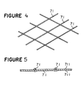
- the metallic mesh may be formed by knitting thin metallic wires as shown in Figures 4,5 or by plating a mesh made of resinous material or by subjecting it to metal vapour deposition to form a metallic layer 711 thereby forming electrically continuous surface. With this structure, loss of the microwave can be minimized to improve efficiency. Further, the mesh is mechanically strengthened and performs the same function as that obtained by the etching operation.
- FIG. 6 is a transverse cross-sectional view showing a mode pattern of another embodiment of an angular type microwave resonance cavity of the present invention.
- Electromagnetic mode in a cross-sectional view is analogous to that shown in Figure 3a.
- the mode is called a square TE111 mode which allows connection of microwaves from the waveguide 3 to the microwave resonance cavity 5.
- a test was conducted by using the same waveguide 3 and the lamp 9 as those in Figure 3 and an rectangular type microwave resonance cavity 5 having a square shape in cross section, a side of which is 80 mm long and having a height of 80 mm. With use of microwaves of a frequency of 2450 MHz and a power of 800 W, it took about 5 seconds before reaching normal condition and coefficient of power reflection of microwave was about 0.1.
- an effective part of the light reflecting plate 11 provided outside of the microwave resonance cavity 5 can be large by reducing the maximum dimension in cross section of the microwave resonance cavity 5 which is parallel to the power feeding port 8 and by utilizing low grade mode in cross section as shown in Figures 3b and 6. Accordingly, allowability in design of the light reflecting plate is increased and efficiency of light is improved.
- excitation of the microwave becomes difficult when the maximum dimension in cross section of the microwave resonance cavity 5 in parallel to the power feeding port 8 is less than half of the wavelength of the microwave, while the advantage as above-mentioned can not be obtained, when the dimension is more than two times of the wavelength of the microwave. Namely, there is limitation in the allowability in design of the light reflecting plate 11. Substantially the same performance as in Figures 3 and 6 can be attained when mode causing excitation of the microwave at the above-mentioned range is used.
- Figure 7 shows another embodiment of the microwave resonance cavity of the present invention in which a reference numeral 7a designates a first element formed by rolling a flat mesh member into a cylindrical shape with both ends opened, a numeral 7b designates a second element made of a flat mesh member which is jointed to one of the open ends of the cylindrical first element 7a to constitute a closing part to capture the microwaves in the first element, a numeral 7c designates a joint portion of the cylindrical first element, a numeral 7d designates a joint portion between the first and second elements 7a, 7b.
- the jointing operation is conducted by welding or brazing to electrically connect the joint portions.
- a annular member 7e is arranged to joint the first and second elements 7a, 7b along the inner circumferential portion of one of the open ends of the first element 7a.
- a annular metallic member 7e is provided along the outer circumferential portion of one of the open ends of the first element 7a in order to joint the first and second elements 7a, 7b.
- a reinforcing flange 7f is attached along the outer circumferential portion of the other open end of the first element 7a in which a reference numeral 7g designates a joint portion between the first element 7a and the reinforcing flange 7f.
- FIG 11 shows a quadrate column type microwave resonance cavity of another embodiment of the present invention.
- the microwave resonance cavity comprises a first element 7a formed by bending a flat mesh member into a quadrate column shape with both ends opened and a second element 7b made of a flat mesh member which is jointed at one of the open ends of the first element 7a to capture the microwaves therein.
- the microwave resonance cavity there is an optimum value for the microwave resonance cavity. It has been found in experiments that the optimum value of transmittance of 90% can be obtained by using the first and second mesh elements 7a, 7b, each being formed by photo-etching a thin stainless steel sheet of 0.1 mm thick into a lattice form in which the pitch of the lattice is 1 mm and the width of wires is 0.1 mm.
- the light transmitting member 7 is constituted by the first and second elements 7a, 7b made of a flat mesh member. Each of the first and second elements is formed by processing a single mesh sheet material and bonded them together.
- the joint portion 7c of the first element 7a and the joint portion 7d between the first and second element 7a, 7b are jointed by welding or brazing.
- This jointing method provides reinforcing effect to the cylindrical light transmitting member 7 in a net form which has a mechanical strength greater than a spherical mesh member. Accordingly, it sufficiently withstands at the time of assembling, maintenance and inspection, whereby there is no problem of deformation or breakdown.
- an annular member 7e is placed at the joint portion 7d between the first and second elements 7a, 7b and the annular member 7e is jointed by means of, for instance, spot welding along the inner or outer circumferential portion of the first and second elements. Accordingly, the cylindrical light transmitting member 7 in a mesh form has much mechanical strength.
- the reinforcing flange 7f is jointed by, for instance, spot welding along the outer circumferential portion of the open end at the side of power feeding port of the first element 7a, to increase a mechanical strength.
- the rectangular-shape mesh member shown in Figure 11 also provides a mechanically strengthened microwave resonance cavity.
- Figure 12 is a cross-sectional view of an important part of the microwave discharge light source apparatus according to another embodiment of the present invention.
- a corner portion 31 is formed in the waveguide 3 so that the surface of the power feeding port 8 is not perpendicularly crossed to the longitudinal axes of the waveguide to which the magnetron 1 is mounted.
- the waveguide 3 is a square type waveguide.
- Figure 12 shows a cross-sectional view which is normal to the direction of an electric field E and the corner portion is an E corner.
- Figure 13 is a cross sectional view showing distribution of the electric field E and the magnetic field H in the waveguide and resonance cavity shown in Figure 12.
- the solid lines E represents the lines of electric force namely an electric field and small circles H represent the lines of magnetic force, namely a magnetic field.
- the microwave resonance cavity 5 shown in Figure 13 is of a cylindrical form.
- the mode in the waveguide 3 is a square TE10 mode and the mode in the microwave resonance cavity 5 is a cylindrical TE111 mode, namely, there is a single projection in an electromagnetic field in every direction.
- the directions of the electric field and the magnetic field are both changed. In this case, an angle ⁇ of the corner portion 31 is 45° to change the direction of the electric field and the magnetic field at a right angle.
- the electromagnetic field mode at the side of waveguide of the power feeding port 8 is a good approximation of the TE10 mode even though the length l of the waveguide is a quarter or smaller as large as the wavelength in the waveguide as shown in Figure 13.
- the cylindrical microwave resonance cavity used in the embodiment shown in Figure 2 is applicable to the microwave resonance cavity of this embodiment. Namely, excellent excitation of the TE111 mode in the cylindrical resonance cavity can be attained from the TE10 mode in the square waveguide as shown in Figure 13. In this case, it might be necessary to modify the shape of the power feeding port shown in Figure 1 because the mode at the waveguide side is not entirely same as the TE10 mode when a value l is small although the same resonance cavity can be used.
- a test was conducted by using a square type waveguide 3 having a cross sectional area of 95 mm x 54 mm in which the angle ⁇ of the corner portion is 45° and the length of l is 8 mm, a cylindrical microwave resonance cavity 5 having a diameter of 80 mm and a height of 90 mm, and a spherical lamp 9 having a diameter of 30 mm in which 0,0798 bar (60 Torr) of argon and 100 mg of mercury are filled.
- the operation of the microwave discharge light souce apparatus having the construction as above-mentioned used for a light source or a film printing apparatus is as follows.
- Figure 14 shows diametrically the film printing apparatus in which the microwave discharge light source apparatus is placed at a position 17 or 18 in a casing 14.
- the microwave discharge light source apparatus placed at the position 17 indicated by the dotted line is the same as the embodiment as shown in Figure 1 provided that it inversely stands and the apparatus at the position 18 indicated by the solid line is the same as the apparatus as shown in Figure 13.
- a film to be printed 15 and a printing film 16 are overlaid on the top surface of the frame 14.
- the printing film 16 is exposed to light from the light source apparatus whereby image transfer is performed from the printed film 15 to the printing film 16.
- a plurality of films to be printed may be overlaid for the purpose of edition. In this case, the overlaid films has a substantial thickness.
- an image to be printed to the printing film 16 becomes out of focus unless the incident angle of light is normal to the surface of the films. Accordingly, the light should be normal to the film surface, namely the light should be parallel light.
- the microwave discharge light source apparatus is arranged in the position 17 in Figure 14, a light beam is spread as indicated by the dotted arrow marks, which is apparently different from the parallel light.
- the position of the light source can be lowered and the light beam irradiated to the object surface becomes a substantial parallel light as shown by the solid arrow marks. Accordingly, an image to be printed is well focused and high quality printing is possible.
- the above-mentioned embodiments has the longitudinal axis of the waveguide, to which a magnetron is mounted, in parallel to the surface of the power feeding port.
- they may have a relation of inclination other than a relation of orthogonally intersecting. The latter provides an advantage of reduction in length. Even in this case, it is possible to obtain a desired mode.
- a first reinforcing member 7h consisting of a metallic ring having a rectangular shape in cross section is provided along the inner rectangular portion of the boundary between a first element 7a of a cavity wall and a second element 7b of a cavity top surface which opposes the power feeding port (not shown).
- the first reinforcing member 7h having an L shape in cross section is used as the metallic ring.
- the first reinforcing member having a triangle having a right angle in cross section is used for the metallic ring.
- Figure 18 shows a microwave cavity 5 in which the first reinforcing member 7h having a circular shape in cross section is used for the metallic ring.
- the microwave cavity 5 as above-mentioned is fabricated by the first element 7a constituting a cylindrical side surface and the second element 7b as a disc-like top surface, the joint portion between the both elements is connected to the reinforcing member by spot welding.
- a second reinforcing member 7i of a metallic bar having a rectangular shape in cross section is attached to the first element 7a of a cylindrical side surface along the axial line of the cylindrical cavity.
- the microwave cavity 5 shown in Figure 20 two metallic bars as the second reinforcing member are attached to the first element 7a constituting a cylindrical side surface in a diametrically opposing position and along the axial direction of the cylindrical body.
- the first reinforcing member 7h of a metallic ring having a rectangular shape in cross section is provided along the boundary between the first element 7a of the side surface of the cavity and the second element 7b of the top surface of the cavity.
- each end of the second reinforcing members 7i is connected to the first reinforcing member 7h and the other end is connected to a flange 7g by spot welding respectively.
- FIG 21 is a cross sectional view of the microwave discharge light source apparatus in which the microwave cavity 5 shown in Figure 20 is used.
- the operation of the apparatus is as follows. Microwaves emitted into the microwave cavity 5 produce a microwave electromagnetic field in the cavity to cause radiation of light in the discharge lamp by discharging. The light is emitted outside at a transmission rate which depends on the thickness of the metallic mesh and a ratio of openings of the cavity. For instance, in order to increase light transmission property and keep an amount of leakage of the microwave at a fixed value or lower, the metallic mesh is so formed that a metallic plate having a thickness of 0.1 mm - 0.2 mm is subjected to photo-etching operation to be a mesh plate having a pitch of 1mm and a wire diameter of 0.1 mm.
- the microwave cavity is fabricated by using the mesh plate as follows.
- a top surface of the cavity as the second element 7b and a cavity side surface as the first element 7a are separately prepared from the metallic mesh sheet material.
- the first reinforcing member 7h of the metallic ring is connected to the metallic mesh of the second element 7b by spot welding.
- the side surface 7a of the cavity is formed by rolling a flat metallic mesh into a cylindrical form.
- the joint portion of the cavity surface and a portion diametrically opposing the joint portion are respectively connected to the second reinforcing members 7i of metallic bars by spot welding.
- each one end of the reinforcing members 7i is connected to the first reinforcing member 7h and each other end is connected to the flange 7g by spot welding, thus the microwave cavity 5 is assembled. Provision of the reinforcing members in the microwave cavity 5 prevents deformation of the microwave cavity 5 caused by thermal reflection during the operation of the lamp and handling at the time of replacement of the lamp or manufacturing steps.
- a rectangular-shaped microwave cavity may be used instead of the cylindrical cavity.
- the reinforcing member has a thermal expansion factor substantially the same as that of the microwave cavity to prevent deformation of the cavity due to difference in the thermal expansion factors.
- a reference numeral 5 designates the microwave resonance cavity and a numeral 7 designates the light transmitting member, both being the same as those in Figure 1.
- a flange 7g is connected to the light transmitting member 7 at the outer surface of the open end at the side of the wave guide 3.
- a frame 14 is secured to the flange 7g.
- the flange 7g is provided with a plurality of threaded holes 19 to be connected to the cavity wall.
- the frame 14 is secured to the cavity wall through the flange 7g (the light tansmitting member is not directly secured to the cavity wall). With this structure, the frame 14 is held without any contact with the light transmitting member 7 and the light transmitting member 7 can be independently attached to and removed from the cavity wall.
- Figure 23 is a cross-sectional view showing another embodiment of the microwave resonance cavity.
- a frame 14 in a channel shape in cross section is placed on the flange 7g in an offset state to cover the light transmitting member and both ends is connected to the flange 7g.
- Figure 24 is a cross-sectional view of the microwave resonance cavity including a supporting part for fixing an electrodeless lamp 9 according to another embodiment of the present invention.
- a lamp supporting part 91 of the electrodeless lamp 9 is secured to the frame 14 placed at the outer side of the light transmitting member 7.
- two or more number of frames 14 may be used although description has been made as to use of a single of the frame 14.
- the electrodeless lamp 9 may be supported at a desired position other than that shown in Figure 24.
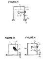
- FIG 25 is a side view of still another embodiment of the microwave cavity resonator.
- a reference numeral 7 designates a light transmitting member made of a material inhibiting transmission of the microwave which is a component of the microwave resonance cavity 5.
- the light transmitting member 7 has a metal layer in a mesh form on the inner or outer surface of a cylindrical body of plastics or glass by plating or vapour-depositing.
- a reference numeral 7j designates a ventilating openings
- a numeral 7g designates a fitting flange of the microwave resonance cavity 5
- a numeral 71 designates through holes for fitting screws.
- the microwave resonance cavity 5 having the construction in which a metallic mesh 7k is formed on the light transmitting member 7 made of rigid plastic or glass by plating or vapour deposition, there is no problem of deformation or breakdown during manufacturing steps of the apparatus and in the handling operation such as replacement of the lamp and work for maintenance. Further, the lamp can be effectively cooled without causing leakage of air fed by a fan when the lamp (not shown) is cooled and air is discharged outside from the ventilating openings 7j after the lamp has been cooled.
- FIG 26 shows another embodiment of the microwave resonance cavity 5 in which a metallic mesh 7m is embedded in the side wall of the light transmitting member 7 made of plastics or glass.
- a lamp supporting bar 91 for holding the lamp 9 is secured to the side wall of the light transmitting member 7 by means of a fastening screw 10. This allows easy work of replacement of the lamp in comparison with the conventional structure.
- a mesh-formed metallic layer 7k and the metallic mesh 7m are electrically connected to the fitting flange 7g of the microwave resonance cavity 5.
- FIG 27 shows another embodiment of the microwave discharge light source apparatus of the present invention.
- a reference numeral 6 designates a cavity wall of the light transmitting member made of a stainless steel mesh which has an opening at the lower portion and a flange 20 at the opening.
- a numeral 21 designates a bottom plate which closes the opening and is provided with a power feeding port 8 communicated with the opening.
- the cavity wall 6 is attached to the bottom plate 21 by means of the flange 20 fitted to screws 22 thereby to form the microwave cavity 5.
- a reference numeral 11 designates a light reflecting plate positioned at the outer side of the cavity wall 6 and connected to the bottom plate 21 by screws 23.
- a reference numeral 24 designates a cut-off pipe provided at the bottom plate 21 and the cut-off pipe 24 is provided with a taper screw portion 24a at a forked portion of the top end of the pipe 24.
- the supporting bar 91 of the electrodeless discharge lamp 9 is inserted in the cut-off pipe 24 and the screw 10 is engaged with the taper screw portion 24a whereby the lamp 9 is held in the microwave cavity 5.
- the light source apparatus can be designed in consideration of only the optical characteristic, i.e. control of distribution of light. Namely, design of the apparatus for various usage can be made by changing only the light reflecting plate 11.
- the electrodeless discharge lamp 9 is held at a desired position in the bottom plate 21 through the supporting bar 91, whereby it does not interrupt light to the light reflecting plate 11. Further, the support of the discharge lamp 9 is provided outside of the microwave circuit by means of the cut-off pipe 24 of the bottom plate 21, whereby there is no effect of the supporting means to the microwave circuit.
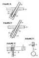
- Figure 28 shows another embodiment of the supporting means in the combination of the supporting bar 91 of the discharge lamp 9 and the cut-off pipe 24 in which springs 25 are placed in an annular recess in the cut-off pipe 24 to grip the supporting bar 91.
- Figure 29 shows another embodiment of the supporting means in which an adhesive 26 is filled in the recess formed in the cut-off pipe to secure the supporting bar 91.
- Figure 30 is a cross-sectional view showing another embodiment of the structure for the supporting bar 91 of the electrodeless discharge lamp 9 in which a reference numeral 61 designates a recess formed in the cavity wall 6, a numeral 27 designates a coil spring, received in the recess 61, with the lower end secured the bottom of the recess 61, a numeral 92 designates a threaded portion formed at the outer end of the supporting bar 91, the threaded portion 92 being engaged with the coil spring 27 thereby supporting the supporting bar 91 and a numeral 30 designates an elastic material having heat resistance property which is placed at the bottom of the recess 61, the elastic material 30 holding the end surface of the supporting bar 91 by contact with it.
- a reference numeral 61 designates a recess formed in the cavity wall 6
- a numeral 27 designates a coil spring, received in the recess 61, with the lower end secured the bottom of the recess 61
- a numeral 92 designates a
- any vibration and shock applied to the supporting bar 91 can be effectively absorbed since the supporting bar 91 is engaged with the coil spring 27. Further, the vibration and shock applied to both the supporting bar and the coil spring can be absorbed by the elastic material 30 since the end surface of the supporting bar is in contact with the elastic material 30 placed in the bottom of the recess 61.
- a metal piece 31 having a threaded portion in the outer circumferential surface may be connected to the end of the supporting bar 91 by an adhesive 23 as shown in Figure 31.
- the cavity wall 6 and the metal piece 31 can be made of material having the same coefficient of thermal expansion to increase reliability of these parts.
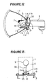
- Figure 32 is a perspective view partly broken of another embodiment of the microwave discharge light source apparatus of the present invention.
- the light source apparatus has a trumpet-shaped reflector 11 with a light reflecting surface at the inside thereof.
- the reflector 11 has a front or an enlarged opening and the rear opening 11a at the opposite side of the enlarged opening.
- the opening 11a is provided with a cylindrical portion or an opening wall 11b extending backward at a relatively small length.
- an annular groove 11c is formed by striking the opening wall outward.
- a fitting flange 11d is formed at the end portion of the opening wall 11b by bending the end portion radially in the outer direction.
- a cylindrical light transmitting member having one end opened and the other end closed is inserted by fitting a pressing ring 31 placed at the other inner end into the annular groove 11c formed in the opening wall 11b.
- the light transmitting member 7 is set at a position that the closed end projects at the side of an effective reflecting surface of the reflector 11.
- the light transmitting member 7 is made of a mesh-formed metallic material hindering to transmit microwaves.
- a disc-like microwave wall body 32 is fitted to the rear surface of the flange 11d of the reflector 11 by screws 33 so as to close the opening 11a, whereby the other end of the light transmitting member 7 is closed thereby to constitute the inner portion; thus providing microwave cavity 5.
- a power feeding port 8 is formed at the central portion of the microwave wall body 32 to lead the microwaves into the microwave cavity 5.
- the electrodeless lamp 9 is placed in the microwave cavity 5 by fixing it at a desired portion in the microwave wall body 32 by a suitable means (not shown).
- the wave guide 3 is attached at the rear side of the microwave wall body 32 to introduce the microwaves into the power feeding port 8 and a microwave oscillator 2 is provided at the rear part of the wave guide 3 to produce the microwaves.
- the light source apparatus of the present embodiment provides the following advantages.
- restrictive elements to form the microwave circuit are only the light transmitting member 7, the opening 11a to secure the light transmitting member and the opening wall 11b. Accordingly, it is possible to design a reflecting surface having various shapes. Further, light transmission can be increased by securing the light transmitting member 7 to the reflector 11. Accordingly, the light transmitting member 7 can be formed by using a thin and fine material. Since the light transmitting member is firmly connected, it is possible to replace the lamp 9 without contacting with a relatively weak mesh portion.
- Figure 33 shows a fixing means for an electrodeless lamp in the microwave discharge light source apparatus in accordance with the present invention.
- the fundamental structure is the same as the conventional structure shown in Figure 1 and therefore, description on the same or corresponding parts is omitted.
- a flange member 34 is formed at the top end of the lamp supporting bar 91 projecting from the lamp wall.
- the flange member 34 is made of ceramics.
- the lamp supporting bar 91 is inserted into an insertion hole 34a formed at a part of the flange member 34 and cement consisting mainly of water glass is filled in the insertion hole to bond the supporting bar 91.
- the flange member 34 is placed in the cavity 5 to bridge the power feeding port 8 and fixed to the cavity wall 6 by means of two bolts 35.
- the lamp 9 is secured to the cavity wall 6 by the two bolts 35; the flange member 34 is in contact with the cavity wall 6 at a relatively broad area and the flange member 34 has a longer insertion hole for the supporting bar, whereby the lamp can be certainly secured at a position in the cavity and there causes no error when a light source is subjected to vibrations by an external force.
- a dielectric material such as ceramics is desirable for the flange member.
- the flange member 34 and the supporting bar 91 is bonded together by use of cement.
- a detachable structure namely the supporting bar 91 is inserted into the insertion hole 34a of the flange member 34 which is previously attached to the cavity wall 6 to thereby secure the lamp 9.
- a cup-shaped member made of silicon is attached at the top end of the supporting bar 91.
- the silicon cap 34b is not critical, but a silicon tape may be wound on the top end of the supporting bar 91.
- the insertion hole 34a for the supporting bar having a large depth can be obtained without increasing the thickness of the cavity wall 6. Accordingly, owing to use of the cushion member, deviation of the lamp setting position can be minimized to a negligible extent.
- the lamp supporting bar 91 may be a part of a discharging pipe. Namely, in manufacturing steps of the lamp, a discharge pipe is connected to the lamp for discharging air and a part of the discharging pipe is bonded at the connecting part of the lamp and the discharging pipe. Then, the discharging pipe is cut to have a predetermined length to be a supporting bar.
Landscapes
- Physics & Mathematics (AREA)
- Electromagnetism (AREA)
- Engineering & Computer Science (AREA)
- Plasma & Fusion (AREA)
- Discharge Lamps And Accessories Thereof (AREA)
- Circuit Arrangements For Discharge Lamps (AREA)
Description
- The present invention relates to a microwave discharge light source apparatus according to the precharacterizing clause of claim 1 (EP-A-0 035 898).
- A microwave discharge light source apparatus having a microwave resonance cavity having a cavity wall surface, a substantial part of which is constituted by a light transmitting member is known in publications such as Japanese Unexamined Utility Model Publication 168167/1982 (Figure 1).
- The conventional apparatus as shown in Figure 1 is constructed in such a manner that microwaves radiated from a
magnetron 1 are passed from amagnetron antenna 2 through awaveguide 3 and are fed into amicrowave resonance cavity 5 through apower feeding port 8. Electric discharge of gas is caused in alamp 9 by the microwaves. Light caused by luminescence of the gas is emitted outside through ametallic mesh 7. The emitted light is reflected by a light reflecting plate (not shown) and so on to shine a surface to be irradiated. In the microwave discharge light source apparatus having the above-mentioned construction, light emitted from thelamp 9 is almost radiated outside through themetallic mesh 7 directly. Accordingly, use of a light reflecting plate placed outside themicrowave resonance cavity 5 effectively reflects the light and therefore, it is easy to control light. Further, it is possible to design the light reflecting plate without causing adverse effect to microwave characteristic of themicrowave resonance cavity 5 since the light reflecting plate is provided the outside of thecavity 5. However, the conventional apparatus has disadvantages that since a mesh formed by knitting fine metallic wires (hereinbelow referred to as wires) as themetallic mesh 7 is usually used, themetallic mesh 7 may be broken due to over-heating by microwave loss which is caused by electrical contact resistance at crossing parts of the wires and efficiency of power feeding to thelamp 9 is poor, hence luminous efficiency is low. Further, the mesh is weak in mechanical strength. When an external force is applied to the mesh, themicrowave resonance cavity 5 is deformed. In this case, resonance condition of the microwaves can not be maintained and incidence of microwave power into themicrowave resonance cavity 5 is difficult. This causes reduction in power for effecting electric discharge in the lamp. Further, when themicrowave resonance cavity 5 is deformed, there causes unevenness in the openings of the metallic mesh 7 (the distance between wires), whereby microwaves may leak from themicrowave resonance cavity 5 at portions having large openings. - EP 0 035 898 A1 discloses a microwave generated plasma light source apparatus with a light transmitting member covering the front opening of the cavity. The efficiency of this apparatus is poor, because more than 50% of light emitted outside from the cavity is reflected by the cavity wall resulting in losses. The distribution of light produced by said apparatus is substantially determined by the shape of the cavity wall.
- A device very similar to the latter is disclosed in Patent Abstracts of Japan,
Volume 8, No. 36 (E-227) (1473), JP-A-58-194242. Accordingly this device has the same deficiencies. - It is an object of the present invention to eliminate the disadvantages of the conventional apparatus and to provide a microwave discharge light source apparatus in which discharge in a lamp is effectively conducted, a microwave resonance cavity is mechanically strengthened and a problem of deformation of the cavity is prevented, and the distribution of light can be changed without changing the shape of the cavity itself.
- According to the invention the object is solved by an apparatus according to
claim 1. - Preferred embodiments are claimed in the subclaims.
- In the drawings:
- Figure 1 is a diagram showing a conventional microwave discharge light source apparatus;
- Figure 2 is a diagram showing an embodiment of the microwave discharge light source apparatus according to the present invention;
- Figure 3a is a longitudinal cross-sectional view showing a mode pattern of an embodiment of the microwave resonance cavity of the present invention;
- Figure 3b is a transverse cross-sectional view taken along a line B-B in Figure 3a;
- Figure 4 is an enlarged perspective view of a mesh before application of metal-plating in a case that a metallic mesh is formed by metallic wires in a network form;
- Figure 5 is an enlarged cross-sectional view of the mesh in Figure 5 after application of plating;
- Figure 6 is a cross-sectional view showing a mode pattern of another embodiment of the microwave resonance cavity of the present invention;
- Figures 7,8,9 and 10 are respectively front views of several embodiments of the microwave resonance cavity of the present invention;
- Figure 11 is a perspective view of still another embodiment of the microwave resonance cavity of the present invention;
- Figure 12 is a cross-sectional view of an important part of another embodiment of the microwave discharge light source apparatus of the present invention;
- Figure 13 is a cross sectional view partly omitted showing radiation of microwaves from a waveguide to a microwave resonance cavity in accordance with the present invention;
- Figure 14 is a diagram showing a film printing apparatus in which an embodiment of the microwave discharge light source apparatus of the present invention is used;
- Figures 15 to 20 are respectively diagrams of several embodiments of the microwave resonance cavity of the present invention;
- Figure 21 is a diagram showing another embodiment of the microwave discharge light source apparatus of the present invention;
- Figure 22 is a cross-sectional view of an embodiment of the light transmitting member used for a microwave discharge light source apparatus of the present invention;
- Figures 23 and 24 are cross-sectional vieww of other embodiments of the light transmitting member of the present invention;
- Figure 25 is a cross-sectional view of another embodiment of the microwave cavity resonator of the present invention;
- Figure 26 is a side view partly cross-sectioned of the resonator including a lamp of the present invention;
- Figure 27 is a longitudinal cross-sectional view of another embodiment of the microwave discharge light source apparatus of the present invention;
- Figures 28 and 29 are respectively cross-sectional views of embodiments of a discharge lamp supporting means of the present invention;
- Figure 30 is an enlarged cross-sectional view of another embodiment of the lamp supporting means used for the present invention;
- Figure 31 is a cross-sectional view of another embodiment of the lamp supporting means;
- Figure 32 is a perspective view partly cross-sectioned of another embodiment of the microwave discharge light source apparatus of the present invention;
- Figure 33 is a cross-sectional view of another embodiment of the microwave cavity of the present invention; and
- Figure 34 is a cross-sectional view of another embodiment of the microwave cavity of the present invention.
- Preferred embodiments of the present invention will be described with reference to drawing.
- Figure 2 shows an embodiment of the microwave discharge light source apparatus of the present invention. In the Figure, a
reference numeral 4 designates a ventilating opening and anumeral 5 designates a cylindrical microwave resonance cavity. At least a part of the wall surface of themicrowave resonance cavity 5 is provided with alight transmitting member 7. Thelight transmitting member 7 is constituted by an electrically continuous metallic mesh and so formed that the sum of three-dimensional angles formed by extension line extending from a point in alamp 9 to thelight transmitting member 7 is 2π steradian or more. Apower feeding port 8 is formed in acavity wall 6 made of metal at a position to be connected to awaveguide 3 to feed microwaves from thewaveguide 3 into themicrowave resonance cavity 5. Thelamp 9 is made of a light transmission substance such as quartz glass and contains a rare gas and mercury and so on. Alamp supporting member 91 made of a dielectric substance such as quartz glass extends from the outer wall of thelamp 9 and is fixed to thecavity wall 6 by means of ascrew 10 so that thelamp 9 is secured to thecavity wall 6. A light reflecting plate 11 surrounds themicrowave resonance cavity 5 to reflect light emitted from thecavity 5. Areference numeral 12 designates a cooling fan for cooling themagnetron 1 and thelamp 9 andnumeral 13 designates a casing for covering the above-mentioned elements. - The operation of the apparatus of the present invention is as follows.
- Microwaves are excited at transmission mode from the
magnetron 1 through themagnetron antenna 2 to thewaveguide 3. The microwaves are fed to themicrowave resonance cavity 5 surrounded by thecavity wall 6 and themetallic mesh 7 through thepower feeding port 8. Rare gas contained in thelamp 9 is initiated to discharge by the microwaves and the lamp wall is heated by energy of the microwaves. The discharge of the gas causes evaporation of mercury and electric discharge of metallic gas such as mercury gas is mainly resulted. Thus, luminescence is resulted at absorption spectra depending on a kind of the metallic gas. - The
metallic mesh 7 functions to reflect the microwaves as metal do and allows light to pass through the openings of the mesh. Namely, themetallic mesh 7 functions as an opaque body for the microwaves and functions as a transparent body for light. Accordingly, light from thelamp 9 is emitted outside through themicrowave resonance cavity 5 and reflected at the light reflecting plate 11. The reflecting plate 11 can be designed to have various shapes depending on how light is used. Since the light reflecting plate 11 is positioned outside of themicrowave resonance cavity 5, design of the light reflecting plate is possible from the optical viewpoint without consideration of affect to microwave characteristics. The microwave power supplying method used in the above-mentioned embodiment is useful for radiating low grade resonance mode and the low grade resonance mode reduces the size of themicrowave resonance cavity 5. - Figure 3a is a longitudinal cross-sectional view showing a mode pattern of an embodiment of the cylindrical microwave resonance cavity of the present invention and Figure 3b is a transverse cross-sectional view taken along a line B-B in Figure 3a. Figure 3a shows in detail connection between transmission mode in the
waveguide 3 and resonance mode in themicrowave resonance cavity 5. In Figures, solid lines and small circles E represent the lines of electric force, i.e. an electric field and dotted lines H represent the lines of magnetic force i.e. a magnetic field. The mode in thewaveguide 3 is a square TE₁₀ mode and the mode in themicrowave resonance cavity 5 is a cylindrical TE₁₁₁ mode, namely, excitation of the microwaves is effected with modes in which there is a single projection of electromagnetic field in every direction. As is understandable from the Figures, connection of the modes is easy because the directions of the electric field and the magnetic field in thewaveguide 3 and themicrowave resonance cavity 5 are coincident. When discharge is caused in thelamp 9, it is considered that the mode in themicrowave resonance cavity 5 is substantially same as the mode shown in the Figure. Accordingly, connection of the modes is also easy. In fact, themicrowave resonance cavity 5 is so designed that resonance is caused under constant discharging condition of the metallic gas such as mercury in thelamp 9. A constant of the microwave of thelamp 9 varies depending on evaporation of the metallic gas until the discharge becomes normal after initiation of the discharge. On account of this, the microwaves are out of condition of resonance until reaching the normal condition. Even in this condition, however, microwave energy necessary to evaporate metal can be supplied from thewaveguide 3 to themicrowave resonance cavity 5 to cause discharge of thelamp 9 without providing any means for changing the condition as the time goes, in thewaveguide 3 or themicrowave resonance cavity 5. This is because themicrowave resonance cavity 5 is small and a relatively strong microwave electromagnetic field is produced even though the microwave is out of the condition of resonance. Accordingly, energy can be supplied to thelamp 9 at the initiation of discharge whereby evaporation of metal quickly takes place and normal condition is obtainable for a short time. A test was conducted by using an apparatus in which thewaveguide 3 has a square shape in cross section of 95 mm x 54 mm, themicrowave resonance cavity 5 is of a cylindrical cavity having a diameter of 80 mm and a height of 90 mm and thelamp 9 is of a spherical shape having a diameter of 30 mm, in which 7999.32 Pa (60 Torr) of argon and 100 mg of mercury are filled. It has been revealed that when microwaves of a frequency of 2450 MHz and power of 800 W, it takes about 5 seconds before reaching normal condition and coefficient of power reflection of the microwaves is 0.1 or below under the condition that matching of the waveguide and the microwave resonance cavity is normal. - The
light transmitting member 7 consisting of a metallic mesh used in the test is formed in such a manner that stainless steel sheet of 0.1 mm thick is subjected to etching to form it in a lattice form in which the pitch of lattice is 1 mm and the width of wire is 0.1 mm. In the conventional mesh formed by knitting thin metal wires, the wires have contact points, namely they are electrically connected through contact resistors. On the contrary, the metallic mesh formed in accordance with the embodiment is electrically continuous. Accordingly, loss in a wall surface current flowing in the inner wall of themicrowave resonance cavity 5 is small, whereby the metallic mesh is not heated by the microwaves, hence thelamp 9 is supplied with power to increase efficiency of discharging. Further, each crossing point ofwires 71 which form a metallic mesh is integral, on account of which the mesh is mechanically rigid and therefore, when thecavity 5 is formed in a three-dimensional structure by using the metallic mesh, there is no problem of deformation of the cavity by an external force at the time of installation of it or by application of heat from the lamp in the discharging. Accordingly, there is no risk of reduction in power which causes discharge of the lamp. Supply of the power to the lamp means that much energy is supplied to the lamp at the initial stage of discharging and the discharge reaches normal condition at a shorter time. The metallic mesh may be formed by knitting thin metallic wires as shown in Figures 4,5 or by plating a mesh made of resinous material or by subjecting it to metal vapour deposition to form ametallic layer 711 thereby forming electrically continuous surface. With this structure, loss of the microwave can be minimized to improve efficiency. Further, the mesh is mechanically strengthened and performs the same function as that obtained by the etching operation. - Figure 6 is a transverse cross-sectional view showing a mode pattern of another embodiment of an angular type microwave resonance cavity of the present invention. Electromagnetic mode in a cross-sectional view is analogous to that shown in Figure 3a. The mode is called a square TE₁₁₁ mode which allows connection of microwaves from the
waveguide 3 to themicrowave resonance cavity 5. As similar to the embodiment shown in Figure 3, a test was conducted by using thesame waveguide 3 and thelamp 9 as those in Figure 3 and an rectangular typemicrowave resonance cavity 5 having a square shape in cross section, a side of which is 80 mm long and having a height of 80 mm. With use of microwaves of a frequency of 2450 MHz and a power of 800 W, it took about 5 seconds before reaching normal condition and coefficient of power reflection of microwave was about 0.1. - Thus, an effective part of the light reflecting plate 11 provided outside of the
microwave resonance cavity 5 can be large by reducing the maximum dimension in cross section of themicrowave resonance cavity 5 which is parallel to thepower feeding port 8 and by utilizing low grade mode in cross section as shown in Figures 3b and 6. Accordingly, allowability in design of the light reflecting plate is increased and efficiency of light is improved. However, excitation of the microwave becomes difficult when the maximum dimension in cross section of themicrowave resonance cavity 5 in parallel to thepower feeding port 8 is less than half of the wavelength of the microwave, while the advantage as above-mentioned can not be obtained, when the dimension is more than two times of the wavelength of the microwave. Namely, there is limitation in the allowability in design of the light reflecting plate 11. Substantially the same performance as in Figures 3 and 6 can be attained when mode causing excitation of the microwave at the above-mentioned range is used. - Figure 7 shows another embodiment of the microwave resonance cavity of the present invention in which a
reference numeral 7a designates a first element formed by rolling a flat mesh member into a cylindrical shape with both ends opened, a numeral 7b designates a second element made of a flat mesh member which is jointed to one of the open ends of the cylindricalfirst element 7a to constitute a closing part to capture the microwaves in the first element, a numeral 7c designates a joint portion of the cylindrical first element, a numeral 7d designates a joint portion between the first andsecond elements - In the microwave resonance cavity as another embodiment shown in Figure 8, a
annular member 7e is arranged to joint the first andsecond elements first element 7a. - In the microwave resonance cavity as another embodiment as shown in Figure 9, a annular
metallic member 7e is provided along the outer circumferential portion of one of the open ends of thefirst element 7a in order to joint the first andsecond elements - Further, in the microwave resonance cavity as another embodiment shown in Figure 10, a reinforcing flange 7f is attached along the outer circumferential portion of the other open end of the
first element 7a in which areference numeral 7g designates a joint portion between thefirst element 7a and the reinforcing flange 7f. - Figure 11 shows a quadrate column type microwave resonance cavity of another embodiment of the present invention. The microwave resonance cavity comprises a
first element 7a formed by bending a flat mesh member into a quadrate column shape with both ends opened and asecond element 7b made of a flat mesh member which is jointed at one of the open ends of thefirst element 7a to capture the microwaves therein. - In practical use of a microwave discharge light source, leakage of the microwave should be minimized and transmittance of light should be large, these characteristics being contradictory. Accordingly, there is an optimum value for the microwave resonance cavity. It has been found in experiments that the optimum value of transmittance of 90% can be obtained by using the first and
second mesh elements light transmitting member 7 is constituted by the first andsecond elements joint portion 7c of thefirst element 7a and thejoint portion 7d between the first andsecond element light transmitting member 7 in a net form which has a mechanical strength greater than a spherical mesh member. Accordingly, it sufficiently withstands at the time of assembling, maintenance and inspection, whereby there is no problem of deformation or breakdown. - In the microwave resonance cavity shown in Figures 8 and 9, an
annular member 7e is placed at thejoint portion 7d between the first andsecond elements annular member 7e is jointed by means of, for instance, spot welding along the inner or outer circumferential portion of the first and second elements. Accordingly, the cylindricallight transmitting member 7 in a mesh form has much mechanical strength. In the cylindricallight transmitting member 7 shown in Figure 10, the reinforcing flange 7f is jointed by, for instance, spot welding along the outer circumferential portion of the open end at the side of power feeding port of thefirst element 7a, to increase a mechanical strength. The rectangular-shape mesh member shown in Figure 11 also provides a mechanically strengthened microwave resonance cavity. - Figure 12 is a cross-sectional view of an important part of the microwave discharge light source apparatus according to another embodiment of the present invention. In the embodiment shown in Figure 12, a
corner portion 31 is formed in thewaveguide 3 so that the surface of thepower feeding port 8 is not perpendicularly crossed to the longitudinal axes of the waveguide to which themagnetron 1 is mounted. Thewaveguide 3 is a square type waveguide. Figure 12 shows a cross-sectional view which is normal to the direction of an electric field E and the corner portion is an E corner. On the other hand, Figure 13 is a cross sectional view showing distribution of the electric field E and the magnetic field H in the waveguide and resonance cavity shown in Figure 12. In Figure 13, the solid lines E represents the lines of electric force namely an electric field and small circles H represent the lines of magnetic force, namely a magnetic field. Themicrowave resonance cavity 5 shown in Figure 13 is of a cylindrical form. The mode in thewaveguide 3 is a square TE₁₀ mode and the mode in themicrowave resonance cavity 5 is a cylindrical TE₁₁₁ mode, namely, there is a single projection in an electromagnetic field in every direction. As shown in Figure 13, in the TE₁₀ mode in thewaveguide 3, the directions of the electric field and the magnetic field are both changed. In this case, an angle ϑ of thecorner portion 31 is 45° to change the direction of the electric field and the magnetic field at a right angle. Accordingly, the electromagnetic field mode at the side of waveguide of thepower feeding port 8 is a good approximation of the TE₁₀ mode even though the length ℓ of the waveguide is a quarter or smaller as large as the wavelength in the waveguide as shown in Figure 13. Accordingly, the cylindrical microwave resonance cavity used in the embodiment shown in Figure 2 is applicable to the microwave resonance cavity of this embodiment. Namely, excellent excitation of the TE₁₁₁ mode in the cylindrical resonance cavity can be attained from the TE₁₀ mode in the square waveguide as shown in Figure 13. In this case, it might be necessary to modify the shape of the power feeding port shown in Figure 1 because the mode at the waveguide side is not entirely same as the TE₁₀ mode when a value ℓ is small although the same resonance cavity can be used. - A test was conducted by using a
square type waveguide 3 having a cross sectional area of 95 mm x 54 mm in which the angle ϑ of the corner portion is 45° and the length of ℓ is 8 mm, a cylindricalmicrowave resonance cavity 5 having a diameter of 80 mm and a height of 90 mm, and aspherical lamp 9 having a diameter of 30 mm in which 0,0798 bar (60 Torr) of argon and 100 mg of mercury are filled. When excited microwaves of a frequency of 2450 MHz and a power of 800 W is used, it took about 5 seconds before reaching normal condition and coefficient of power reflection of the microwave was 0.1 or lower in the condition that matching of the waveguide and the microwave resonance cavity is normal. When the corner portion having the construction as above-mentioned is used, good characteristics can be obtained even though the length from the corner portion to the power feeding port is short, particularly even though ℓ = 0. Namely, excellent characteristic can be obtained even in the case of the length ℓ being 1/2 of the wavelength in the waveguide or lower (it is considered that mode other than the TE₁₀ mode as a principal mode is mixed at the power feeding port). - The operation of the microwave discharge light souce apparatus having the construction as above-mentioned used for a light source or a film printing apparatus is as follows.
- Figure 14 shows diametrically the film printing apparatus in which the microwave discharge light source apparatus is placed at a
position casing 14. The microwave discharge light source apparatus placed at theposition 17 indicated by the dotted line is the same as the embodiment as shown in Figure 1 provided that it inversely stands and the apparatus at theposition 18 indicated by the solid line is the same as the apparatus as shown in Figure 13. A film to be printed 15 and aprinting film 16 are overlaid on the top surface of theframe 14. Theprinting film 16 is exposed to light from the light source apparatus whereby image transfer is performed from the printedfilm 15 to theprinting film 16. A plurality of films to be printed may be overlaid for the purpose of edition. In this case, the overlaid films has a substantial thickness. Accordingly, an image to be printed to theprinting film 16 becomes out of focus unless the incident angle of light is normal to the surface of the films. Accordingly, the light should be normal to the film surface, namely the light should be parallel light. When the microwave discharge light source apparatus is arranged in theposition 17 in Figure 14, a light beam is spread as indicated by the dotted arrow marks, which is apparently different from the parallel light. On the other hand, when the light source apparatus is placed at theposition 18, the position of the light source can be lowered and the light beam irradiated to the object surface becomes a substantial parallel light as shown by the solid arrow marks. Accordingly, an image to be printed is well focused and high quality printing is possible. - In the embodiment shown in Figures 12 description has been made as to the corner portion having the E corner. However, the same function can be obtained by using an H corner.
- The above-mentioned embodiments has the longitudinal axis of the waveguide, to which a magnetron is mounted, in parallel to the surface of the power feeding port. However, they may have a relation of inclination other than a relation of orthogonally intersecting. The latter provides an advantage of reduction in length. Even in this case, it is possible to obtain a desired mode.
- Several embodiments of the modified
microwave cavity 5 in accordance with the present invention will be described. - In the
microwave cavity 5 shown in Figure 15, a first reinforcingmember 7h consisting of a metallic ring having a rectangular shape in cross section is provided along the inner rectangular portion of the boundary between afirst element 7a of a cavity wall and asecond element 7b of a cavity top surface which opposes the power feeding port (not shown). - In the embodiment shown in Figure 16, the first reinforcing
member 7h having an L shape in cross section is used as the metallic ring. - In the embodiment shown in Figure 17, the first reinforcing member having a triangle having a right angle in cross section is used for the metallic ring.
- Figure 18 shows a
microwave cavity 5 in which the first reinforcingmember 7h having a circular shape in cross section is used for the metallic ring. - In a case that the
microwave cavity 5 as above-mentioned is fabricated by thefirst element 7a constituting a cylindrical side surface and thesecond element 7b as a disc-like top surface, the joint portion between the both elements is connected to the reinforcing member by spot welding. - In the
microwave cavity 5 shown in Figure 19, a second reinforcingmember 7i of a metallic bar having a rectangular shape in cross section is attached to thefirst element 7a of a cylindrical side surface along the axial line of the cylindrical cavity. - In the
microwave cavity 5 shown in Figure 20, two metallic bars as the second reinforcing member are attached to thefirst element 7a constituting a cylindrical side surface in a diametrically opposing position and along the axial direction of the cylindrical body. In addition, the first reinforcingmember 7h of a metallic ring having a rectangular shape in cross section is provided along the boundary between thefirst element 7a of the side surface of the cavity and thesecond element 7b of the top surface of the cavity. In this case, each end of the second reinforcingmembers 7i is connected to the first reinforcingmember 7h and the other end is connected to aflange 7g by spot welding respectively. - Figure 21 is a cross sectional view of the microwave discharge light source apparatus in which the
microwave cavity 5 shown in Figure 20 is used. The operation of the apparatus is as follows. Microwaves emitted into themicrowave cavity 5 produce a microwave electromagnetic field in the cavity to cause radiation of light in the discharge lamp by discharging. The light is emitted outside at a transmission rate which depends on the thickness of the metallic mesh and a ratio of openings of the cavity. For instance, in order to increase light transmission property and keep an amount of leakage of the microwave at a fixed value or lower, the metallic mesh is so formed that a metallic plate having a thickness of 0.1 mm - 0.2 mm is subjected to photo-etching operation to be a mesh plate having a pitch of 1mm and a wire diameter of 0.1 mm. The microwave cavity is fabricated by using the mesh plate as follows. A top surface of the cavity as thesecond element 7b and a cavity side surface as thefirst element 7a are separately prepared from the metallic mesh sheet material. The first reinforcingmember 7h of the metallic ring is connected to the metallic mesh of thesecond element 7b by spot welding. Theside surface 7a of the cavity is formed by rolling a flat metallic mesh into a cylindrical form. The joint portion of the cavity surface and a portion diametrically opposing the joint portion are respectively connected to the second reinforcingmembers 7i of metallic bars by spot welding. Then, each one end of the reinforcingmembers 7i is connected to the first reinforcingmember 7h and each other end is connected to theflange 7g by spot welding, thus themicrowave cavity 5 is assembled. Provision of the reinforcing members in themicrowave cavity 5 prevents deformation of themicrowave cavity 5 caused by thermal reflection during the operation of the lamp and handling at the time of replacement of the lamp or manufacturing steps. - A rectangular-shaped microwave cavity may be used instead of the cylindrical cavity. In this case, it is preferable to provide a metallic bar at the corner portion. Further, it is preferable that the reinforcing member has a thermal expansion factor substantially the same as that of the microwave cavity to prevent deformation of the cavity due to difference in the thermal expansion factors.
- Another embodiment of the microwave resonance cavity of the present invention will be described.
- In Figure 22, a
reference numeral 5 designates the microwave resonance cavity and anumeral 7 designates the light transmitting member, both being the same as those in Figure 1. Aflange 7g is connected to thelight transmitting member 7 at the outer surface of the open end at the side of thewave guide 3. Aframe 14 is secured to theflange 7g. Theflange 7g is provided with a plurality of threadedholes 19 to be connected to the cavity wall. Theframe 14 is secured to the cavity wall through theflange 7g (the light tansmitting member is not directly secured to the cavity wall). With this structure, theframe 14 is held without any contact with thelight transmitting member 7 and thelight transmitting member 7 can be independently attached to and removed from the cavity wall. - Figure 23 is a cross-sectional view showing another embodiment of the microwave resonance cavity. In Figure 23, a
frame 14 in a channel shape in cross section is placed on theflange 7g in an offset state to cover the light transmitting member and both ends is connected to theflange 7g. - Figure 24 is a cross-sectional view of the microwave resonance cavity including a supporting part for fixing an
electrodeless lamp 9 according to another embodiment of the present invention. In Figure 24, alamp supporting part 91 of theelectrodeless lamp 9 is secured to theframe 14 placed at the outer side of thelight transmitting member 7. In the embodiments described above, two or more number offrames 14 may be used although description has been made as to use of a single of theframe 14. Theelectrodeless lamp 9 may be supported at a desired position other than that shown in Figure 24. - Figure 25 is a side view of still another embodiment of the microwave cavity resonator. In the Figure, a
reference numeral 7 designates a light transmitting member made of a material inhibiting transmission of the microwave which is a component of themicrowave resonance cavity 5. Thelight transmitting member 7 has a metal layer in a mesh form on the inner or outer surface of a cylindrical body of plastics or glass by plating or vapour-depositing. In the Figure, a reference numeral 7j designates a ventilating openings, a numeral 7g designates a fitting flange of themicrowave resonance cavity 5 and a numeral 71 designates through holes for fitting screws. - In the
microwave resonance cavity 5 having the construction in which ametallic mesh 7k is formed on thelight transmitting member 7 made of rigid plastic or glass by plating or vapour deposition, there is no problem of deformation or breakdown during manufacturing steps of the apparatus and in the handling operation such as replacement of the lamp and work for maintenance. Further, the lamp can be effectively cooled without causing leakage of air fed by a fan when the lamp (not shown) is cooled and air is discharged outside from the ventilating openings 7j after the lamp has been cooled. - Figure 26 shows another embodiment of the
microwave resonance cavity 5 in which ametallic mesh 7m is embedded in the side wall of thelight transmitting member 7 made of plastics or glass. Alamp supporting bar 91 for holding thelamp 9 is secured to the side wall of thelight transmitting member 7 by means of afastening screw 10. This allows easy work of replacement of the lamp in comparison with the conventional structure. - In the embodiments described above, a mesh-formed
metallic layer 7k and themetallic mesh 7m are electrically connected to thefitting flange 7g of themicrowave resonance cavity 5. - Figure 27 shows another embodiment of the microwave discharge light source apparatus of the present invention. In Figure 29, the same reference numerals as in Figure 2 designate the same or corresponding parts and therefore, description of these parts are omitted. A
reference numeral 6 designates a cavity wall of the light transmitting member made of a stainless steel mesh which has an opening at the lower portion and aflange 20 at the opening. A numeral 21 designates a bottom plate which closes the opening and is provided with apower feeding port 8 communicated with the opening. Thecavity wall 6 is attached to thebottom plate 21 by means of theflange 20 fitted toscrews 22 thereby to form themicrowave cavity 5. A reference numeral 11 designates a light reflecting plate positioned at the outer side of thecavity wall 6 and connected to thebottom plate 21 byscrews 23. Areference numeral 24 designates a cut-off pipe provided at thebottom plate 21 and the cut-offpipe 24 is provided with a taper screw portion 24a at a forked portion of the top end of thepipe 24. The supportingbar 91 of theelectrodeless discharge lamp 9 is inserted in the cut-offpipe 24 and thescrew 10 is engaged with the taper screw portion 24a whereby thelamp 9 is held in themicrowave cavity 5. - In the microwave discharge light source apparatus having the above-mentioned construction, since the light reflecting plate 11 is independent from a microwave circuit consisting of the
magnetron antenna 2, thewaveguide 3, thepower feeding port 10 and themicrowave cavity 5 inclusive of the inner space and the inner wall surface, the light source apparatus can be designed in consideration of only the optical characteristic, i.e. control of distribution of light. Namely, design of the apparatus for various usage can be made by changing only the light reflecting plate 11. Theelectrodeless discharge lamp 9 is held at a desired position in thebottom plate 21 through the supportingbar 91, whereby it does not interrupt light to the light reflecting plate 11. Further, the support of thedischarge lamp 9 is provided outside of the microwave circuit by means of the cut-offpipe 24 of thebottom plate 21, whereby there is no effect of the supporting means to the microwave circuit. - Figure 28 shows another embodiment of the supporting means in the combination of the supporting
bar 91 of thedischarge lamp 9 and the cut-offpipe 24 in which springs 25 are placed in an annular recess in the cut-offpipe 24 to grip the supportingbar 91. - Figure 29 shows another embodiment of the supporting means in which an adhesive 26 is filled in the recess formed in the cut-off pipe to secure the supporting
bar 91. - Figure 30 is a cross-sectional view showing another embodiment of the structure for the supporting
bar 91 of theelectrodeless discharge lamp 9 in which areference numeral 61 designates a recess formed in thecavity wall 6, a numeral 27 designates a coil spring, received in therecess 61, with the lower end secured the bottom of therecess 61, a numeral 92 designates a threaded portion formed at the outer end of the supportingbar 91, the threadedportion 92 being engaged with thecoil spring 27 thereby supporting the supportingbar 91 and a numeral 30 designates an elastic material having heat resistance property which is placed at the bottom of therecess 61, theelastic material 30 holding the end surface of the supportingbar 91 by contact with it. - In the above-mentioned supporting structure, any vibration and shock applied to the supporting
bar 91 can be effectively absorbed since the supportingbar 91 is engaged with thecoil spring 27. Further, the vibration and shock applied to both the supporting bar and the coil spring can be absorbed by theelastic material 30 since the end surface of the supporting bar is in contact with theelastic material 30 placed in the bottom of therecess 61. - For the threaded portion formed at the outer end of the supporting
bar 91, ametal piece 31 having a threaded portion in the outer circumferential surface may be connected to the end of the supportingbar 91 by an adhesive 23 as shown in Figure 31. In this case, thecavity wall 6 and themetal piece 31 can be made of material having the same coefficient of thermal expansion to increase reliability of these parts. - Figure 32 is a perspective view partly broken of another embodiment of the microwave discharge light source apparatus of the present invention.
- The light source apparatus has a trumpet-shaped reflector 11 with a light reflecting surface at the inside thereof. The reflector 11 has a front or an enlarged opening and the rear opening 11a at the opposite side of the enlarged opening. The opening 11a is provided with a cylindrical portion or an opening wall 11b extending backward at a relatively small length. In the inner circumferential surface of the opening wall 11b, an annular groove 11c is formed by striking the opening wall outward. A fitting flange 11d is formed at the end portion of the opening wall 11b by bending the end portion radially in the outer direction.
- In the inner circumferential surface of the opening wall 11b of the reflector 11, a cylindrical light transmitting member having one end opened and the other end closed is inserted by fitting a
pressing ring 31 placed at the other inner end into the annular groove 11c formed in the opening wall 11b. Thelight transmitting member 7 is set at a position that the closed end projects at the side of an effective reflecting surface of the reflector 11. Thelight transmitting member 7 is made of a mesh-formed metallic material hindering to transmit microwaves. - A disc-like
microwave wall body 32 is fitted to the rear surface of the flange 11d of the reflector 11 byscrews 33 so as to close the opening 11a, whereby the other end of thelight transmitting member 7 is closed thereby to constitute the inner portion; thus providingmicrowave cavity 5. Apower feeding port 8 is formed at the central portion of themicrowave wall body 32 to lead the microwaves into themicrowave cavity 5. Theelectrodeless lamp 9 is placed in themicrowave cavity 5 by fixing it at a desired portion in themicrowave wall body 32 by a suitable means (not shown). - The
wave guide 3 is attached at the rear side of themicrowave wall body 32 to introduce the microwaves into thepower feeding port 8 and amicrowave oscillator 2 is provided at the rear part of thewave guide 3 to produce the microwaves. - The light source apparatus of the present embodiment provides the following advantages. When the shape of the light reflecting surface is to be designed, restrictive elements to form the microwave circuit are only the
light transmitting member 7, the opening 11a to secure the light transmitting member and the opening wall 11b. Accordingly, it is possible to design a reflecting surface having various shapes. Further, light transmission can be increased by securing thelight transmitting member 7 to the reflector 11. Accordingly, thelight transmitting member 7 can be formed by using a thin and fine material. Since the light transmitting member is firmly connected, it is possible to replace thelamp 9 without contacting with a relatively weak mesh portion. - Figure 33 shows a fixing means for an electrodeless lamp in the microwave discharge light source apparatus in accordance with the present invention. In Figure 33, the fundamental structure is the same as the conventional structure shown in Figure 1 and therefore, description on the same or corresponding parts is omitted.
- In the embodiment shown in Figure 33, a
flange member 34 is formed at the top end of thelamp supporting bar 91 projecting from the lamp wall. Theflange member 34 is made of ceramics. Thelamp supporting bar 91 is inserted into an insertion hole 34a formed at a part of theflange member 34 and cement consisting mainly of water glass is filled in the insertion hole to bond the supportingbar 91. Theflange member 34 is placed in thecavity 5 to bridge thepower feeding port 8 and fixed to thecavity wall 6 by means of twobolts 35. - In the microwave discharge light source apparatus having the above-mentioned construction, the
lamp 9 is secured to thecavity wall 6 by the twobolts 35; theflange member 34 is in contact with thecavity wall 6 at a relatively broad area and theflange member 34 has a longer insertion hole for the supporting bar, whereby the lamp can be certainly secured at a position in the cavity and there causes no error when a light source is subjected to vibrations by an external force. - Use of material such as metal for the flange member results in introduction of a highly conductive member in the cavity to thereby largely change an impedance in the cavity, with the consequence that it is difficult to feed a sufficient amount of the microwaves into the cavity. Accordingly, a dielectric material such as ceramics is desirable for the flange member.
- In the above-mentioned embodiment, the
flange member 34 and the supportingbar 91 is bonded together by use of cement. However, it is possible to use a detachable structure, namely the supportingbar 91 is inserted into the insertion hole 34a of theflange member 34 which is previously attached to thecavity wall 6 to thereby secure thelamp 9. In this case, it is necessary to prevent thelamp 9 from coming off by interposing a cushion substance between the supportingbar 91 and the insertion hole 34a. - In another embodiment shown in Figure 34, a cup-shaped member made of silicon is attached at the top end of the supporting
bar 91. However, use of the silicon cap 34b is not critical, but a silicon tape may be wound on the top end of the supportingbar 91. Thus, by winding the silicon tape or attaching the silicon cap, the insertion hole 34a for the supporting bar having a large depth can be obtained without increasing the thickness of thecavity wall 6. Accordingly, owing to use of the cushion member, deviation of the lamp setting position can be minimized to a negligible extent. - The
lamp supporting bar 91 may be a part of a discharging pipe. Namely, in manufacturing steps of the lamp, a discharge pipe is connected to the lamp for discharging air and a part of the discharging pipe is bonded at the connecting part of the lamp and the discharging pipe. Then, the discharging pipe is cut to have a predetermined length to be a supporting bar.
Claims (45)
- A microwave discharge light source apparatus comprising a microwave resonance cavity (5) having a wall surface, a substantial part of which is constituted by a light transmitting member (7) formed by a mesh member (71, 711) having a conductive surface, said microwave resonance cavity (5) receiving microwaves from a waveguide (3) through a power feeding port (8), and a lamp (9) placed in said microwave resonance cavity (5) at such a position that, chosen a point of said lamp (9) as reference point, said light transmitting member (7) is subtended by a solid angle of 2π steradian or more, characterized in that said mesh member is formed by wires which are partially adjacently surrounding each other at the crossing points of the mesh, the wires at said crossing points being integrally connected without any substantial electrical contact resistance, so that the mesh member (7) of said microwave resonance cavity (5) is mechanically rigid and is not heated by the microwaves.
- The microwave discharge light source apparatus according to claim 1, characterized in that said microwave resonance cavity (5) is excited by a cylindrical TE₁₁₁ mode.
- The microwave discharge light source apparatus according to claim 1, characterized in that said microwave resonance cavity (5) is excited by a square TE₁₁₁ mode.
- The microwave discharge light source apparatus according to claim 1, characterized in that the maximum dimension in a cross section of said microwave resonance cavity (5) parallel to said power feeding port (8) is 1/2 to 2 times as long as the wavelength of said microwaves.
- The microwave discharge light source apparatus according to claim 1, characterized in that said microwave resonance cavity (5) comprises a first element (7a) formed by rolling a flat mesh member into a cylindrical form with both ends opened and a second element (7b) made of a flat mesh member which closes one of the open ends of said first element (7a) to capture said microwaves in said first element (7a), wherein said power feeding port (8) is arranged at the other open end of said first element (7a).
- The microwave discharge light source apparatus according to claim 1, characterized in that a corner portion (31) is provided in said waveguide (3).
- The microwave discharge light source apparatus according to claim 1 or 5, characterized in that said light transmitting member (7) is provided with a reinforcing member (7g 7h,7i) which is placed along at least a part of said light transmitting member (7).
- The microwave discharge light source apparatus according to claim 1, characterized in that said light transmitting member (7) is placed on the surface of a surrounding member which allows transmission of light but prevents air from passing through.
- The microwave discharge light source apparatus according to claim 1, characterized in that said light transmitting member (7) is provided with a lamp fixing means (10,91).
- The microwave discharge light source apparatus according to claim 1, characterized in that said lamp (9) is provided with a lamp supporting bar (91) which is integral with the lamp wall.
- The microwave discharge light source apparatus according to claim 1, characterized in that said microwave resonance cavity (5) is provided at the outer side with a light reflecting plate (11) for reflecting light emitted from said microwave resonance cavity (5).
- The microwave discharge light source apparatus according to claim 1 or 5, characterized in that said light transmitting member (7) is fixed to a bottom plate (6) in which said power feeding port (8) is formed.
- The microwave discharge light source apparatus according to claim 5, characterized in that said first element (7a) has a circular cross section.
- The microwave discharge light source apparatus according to claim 5, characterized in that said first element (7a) has a rectangular cross section.
- The microwave discharge light source apparatus according to claim 5, 13 or 14, characterized in that said first element (7a) is welded to said second element (7b).
- The microwave discharge light source apparatus according to claim 5, 13 or 14, characterized in that said first element (7a) is brazed to said second element (7b).
- The microwave discharge light source apparatus according to claim 6, characterized in that said corner portion (31) of said waveguide (3) is an E corner.
- The microwave discharge light source apparatus according to claim 6, characterized in that said corner portion (31) of said waveguide is a H corner.
- The microwave discharge light source apparatus according to any one of claim 7 and 13 through 16, characterized in that said reinforcing member (7h) is provided along the boundary between the first and second elements (7a,7b) of said light transmitting member.
- The microwave discharge light source apparatus according to any one of claims 7 and 13 through 16, characterized in that said reinforcing member (7i) is provided along the axial line formed by rolling said first element (7a)of said light transmitting member (7) in a cylindrical form.
- The microwave discharge light source apparatus according to any one of claims 7 and 13 through 16, characterized in that there are two reinforcing members (7h,7i) and said reinforcing members are provided along said first element (7a) and along the boundary between said first and second elements (7a,7b) of said light transmitting member (7).
- The microwave discharge light source apparatus according to claim 7, characterized in that said reinforcing member (7g) is a flange connected to the outer circumference of the open end of said first element (7a) to extend outwardly.
- The microwave discharge light source apparatus according to any one of claims 7, 13 through 16, and 20 through 22, characterized in that the coefficient of thermal expansion of said reinforcing member (7g,7h,7i) is substantially equal to that of said microwave resonance cavity (5) in case that said reinforcing member is jointed to said microwave resonance cavity.
- The microwave discharge light source apparatus according to claim 7 or 22, characterized in that said reinforcing member (7h,7i) has a fixing means to fix a lamp supporting member (91) of said lamp (9).
- The microwave discharge light source apparatus according to any of claim 7 and 13 through 16, characterized in that said a frame (14) surrounds said light transmitting member (7).
- The microwave discharge light source apparatus according to any of claim 7, 19, 20, 21, 22, 24 and 25, characterized in that said frame (14) is secured to an end portion of said waveguide (3).
- The microwave discharge light source apparatus according to claim 7 or 25, characterized in that said frame (14) is placed at the outer side of said light transmitting member (7) in a non-contact state.
- The microwave discharge light source apparatus according to claim 8, characterized in that said surrounding member preventing air from passing through is made of plastics or glass.
- The microwave discharge light source apparatus according to claim 10, characterized in that said lamp supporting bar (91) is secured to a bottom plate (21).
- The microwave discharge light source apparatus according to claim 29, characterized in that said lamp supporting bar (91) is supported by a cut-off pipe (24) formed in the bottom plate (21), said cut-off pipe (24) being provided with a tapered, threaded portion (24a) formed in a forked part at the top thereof.
- The microwave discharge light source apparatus according to claim 29, characterized in that said lamp supporting bar (91) is supported by a cut-off pipe (24) provided in said bottom plate (21) by means of springs (25).
- The microwave discharge light source apparatus according to claim 29, characterized in that said lamp supporting bar (91) is supported by a cut-off pipe (24) formed in said bottom plate (21) by means of an adhesive (26).
- The microwave discharge light source apparatus according to claim 29, characterized in that a recess (61) is formed in said bottom plate (21), a coil spring (27) is received in said recess (61) with its one end fixed to said recess (61) and said coil spring (27) is engaged with a threaded portion (92) formed in an end of said lamp supporting bar (91).
- The microwave discharge light source apparatus according to claim 29, characterized in that said lamp supporting bar (91) is supported by said bottom plate (21) through a flange member (34) having an insertion hole (34a) for the supporting bar (91).
- The microwave discharge light source apparatus according to any one of claims 10 and 30 through 34, characterized in that said lamp supporting bar (91) is a part of a discharge pipe which is used for manufacturing said lamp (9).
- The microwave discharge light source apparatus according to claim 11, characterized in that said light reflecting plate (11) is secured to said microwave cavity wall in one piece.
- The microwave discharge light source apparatus according to claim 15, characterized in that said first and second elements (7a,7b) are jointed through an annular member (7e) placed along the inner circumferential part of one open end of said first element.
- The microwave discharge light source appparatus according to claim 15, characterized in that said first and second elements (7a,7b) are jointed through an annular member (7e) placed along the outer circumferential part of one open end of said first element (7a).
- The microwave discharge light source apparatus according to claim 21, characterized in that said reinforcing members (7h,7i) provided along the first element (7a) and along the boundary between said first and second elements (7a,7b) are mechanically jointed to each other.
- The microwave discharge light source apparatus according to claim 28, characterized in that said surrounding member is a one piece body formed by plating or vapour deposition of metal in a mesh form on a light transmitting substance of plastics or glass.
- The microwave discharge light source apparatus according to claim 28, characterized in that said surrounding member is a one piece body formed by embedding a metallic mesh in a light transmitting substance of plastics or glass.
- The microwave discharge light source apparatus according to claim 33, characterized in that said threaded portion (92) is constituted by a threaded body of metal which is fitted to said lamp supporting bar (91).
- The microwave discharge light source apparatus according to claim 34, characterized in that said lamp supporting bar (91) is detachably fitted to said flange member (34).
- The microwave discharge light source apparatus according to claim 34 or 43, characterized in that said flange member (34) is made of a dielectric substance.
- The microwave discharge light source apparatus according to claim 43, characterized in that the top end of said lamp supporting bar (91) is covered by an elastic material and is inserted into said flange member (34).
Applications Claiming Priority (22)
| Application Number | Priority Date | Filing Date | Title |
|---|---|---|---|
| JP39980/84 | 1984-03-02 | ||
| JP59039980A JPS60185399A (en) | 1984-03-02 | 1984-03-02 | Microwave discharge light source |
| JP59090343A JPS60235351A (en) | 1984-05-07 | 1984-05-07 | Light source device for microwave discharge |
| JP90345/84 | 1984-05-07 | ||
| JP66299/84 | 1984-05-07 | ||
| JP59090345A JPS60235302A (en) | 1984-05-07 | 1984-05-07 | Microwave discharge light source unit |
| JP59090346A JPS60235325A (en) | 1984-05-07 | 1984-05-07 | Light source unit for microwave discharge |
| JP6630084U JPS60177461U (en) | 1984-05-07 | 1984-05-07 | Microwave discharge light source device |
| JP66300/84 | 1984-05-07 | ||
| JP66298/84 | 1984-05-07 | ||
| JP6629984U JPS60177460U (en) | 1984-05-07 | 1984-05-07 | Microwave discharge light source device |
| JP90346/84 | 1984-05-07 | ||
| JP90343/84 | 1984-05-07 | ||
| JP6629884U JPS60177459U (en) | 1984-05-07 | 1984-05-07 | Microwave discharge light source device |
| JP91369/84 | 1984-05-08 | ||
| JP59091369A JPS60235398A (en) | 1984-05-08 | 1984-05-08 | Microwave discharge light source |
| JP85101/84 | 1984-06-08 | ||
| JP8510184U JPS61799U (en) | 1984-06-08 | 1984-06-08 | Microwave discharge light source device |
| JP122110/84U | 1984-08-09 | ||
| JP12211084U JPS6137000U (en) | 1984-08-09 | 1984-08-09 | Microwave discharge light source device |
| JP219926/84 | 1984-10-19 | ||
| JP59219926A JPS6199264A (en) | 1984-10-19 | 1984-10-19 | Microwave electric-discharge light source |
Publications (3)
| Publication Number | Publication Date |
|---|---|
| EP0153745A2 EP0153745A2 (en) | 1985-09-04 |
| EP0153745A3 EP0153745A3 (en) | 1986-12-03 |
| EP0153745B1 true EP0153745B1 (en) | 1991-05-15 |
Family
ID=27581977
Family Applications (1)
| Application Number | Title | Priority Date | Filing Date |
|---|---|---|---|
| EP85102201A Expired EP0153745B1 (en) | 1984-03-02 | 1985-02-28 | Microwave discharge light source apparatus |
Country Status (7)
| Country | Link |
|---|---|
| US (1) | US4673846A (en) |
| EP (1) | EP0153745B1 (en) |
| AU (1) | AU574435B2 (en) |
| CA (1) | CA1273050A (en) |
| DE (1) | DE3582810D1 (en) |
| HK (1) | HK81591A (en) |
| SG (1) | SG81091G (en) |
Families Citing this family (35)
| Publication number | Priority date | Publication date | Assignee | Title |
|---|---|---|---|---|
| US4812957A (en) * | 1985-07-23 | 1989-03-14 | Fusion Systems Corporation | Optical system for uniform illumination of a plane surface |
| US4933602A (en) * | 1987-03-11 | 1990-06-12 | Hitachi, Ltd. | Apparatus for generating light by utilizing microwave |
| JPH07111918B2 (en) * | 1987-07-28 | 1995-11-29 | 三菱電機株式会社 | Microwave discharge light source device |
| JPH0665178B2 (en) * | 1988-02-23 | 1994-08-22 | 株式会社オーク製作所 | Annular electrodeless discharge light source device and lighting method thereof |
| US4887192A (en) * | 1988-11-04 | 1989-12-12 | Fusion Systems Corporation | Electrodeless lamp having compound resonant structure |
| US5142198A (en) * | 1989-12-21 | 1992-08-25 | Applied Science And Technology, Inc. | Microwave reactive gas discharge device |
| JPH0776673B2 (en) * | 1990-01-19 | 1995-08-16 | 三菱電機株式会社 | Image heating device |
| US5420390A (en) * | 1990-01-19 | 1995-05-30 | Mitsubishi Denki Kabushiki Kaisha | Image heating apparatus using a microwave discharge plasma lamp |
| US5051663A (en) * | 1990-03-26 | 1991-09-24 | Fusion Systems Corporation | Electrodeless lamp with improved bulb mounting arrangement |
| IL117972A (en) * | 1995-04-21 | 1999-06-20 | Fusion Lighting Inc | Compact microwave lamp |
| US5811936A (en) * | 1996-01-26 | 1998-09-22 | Fusion Lighting, Inc. | One piece microwave container screens for electrodeless lamps |
| US5841233A (en) * | 1996-01-26 | 1998-11-24 | Fusion Lighting, Inc. | Method and apparatus for mounting a dichroic mirror in a microwave powered lamp assembly using deformable tabs |
| US6031333A (en) * | 1996-04-22 | 2000-02-29 | Fusion Lighting, Inc. | Compact microwave lamp having a tuning block and a dielectric located in a lamp cavity |
| US5844376A (en) * | 1996-07-11 | 1998-12-01 | Osram Sylvania Inc. | Electrodeless high intensity discharge lamp with split lamp stem |
| WO1998056213A1 (en) * | 1997-06-04 | 1998-12-10 | Fusion Lighting, Inc. | Method and apparatus for improved electrodeless lamp screen |
| US5925987A (en) * | 1997-07-18 | 1999-07-20 | Hartmann & Braun Gmbh & Co. Kg | Printed circuit board mounted electrodeless gas discharge lamp |
| JP2000261104A (en) | 1999-03-08 | 2000-09-22 | Matsushita Electric Ind Co Ltd | Semiconductor laser device and method of manufacturing the same |
| GB2353897B (en) * | 1999-08-31 | 2002-02-20 | Lg Electronics Inc | Microwave lighting apparatus |
| RU2161875C1 (en) * | 1999-11-29 | 2001-01-10 | Государственное унитарное предприятие "Всероссийский электротехнический институт им. В.И. Ленина" | Shf driver of electrode-free gaseous-discharge lamp |
| US6737809B2 (en) | 2000-07-31 | 2004-05-18 | Luxim Corporation | Plasma lamp with dielectric waveguide |
| US7429818B2 (en) * | 2000-07-31 | 2008-09-30 | Luxim Corporation | Plasma lamp with bulb and lamp chamber |
| US6922021B2 (en) * | 2000-07-31 | 2005-07-26 | Luxim Corporation | Microwave energized plasma lamp with solid dielectric waveguide |
| RU2185004C2 (en) * | 2000-09-11 | 2002-07-10 | Государственное унитарное предприятие "Всероссийский электротехнический институт" им. В.И.Ленина" | Microwave exciter of electrodeless gas-discharge lamp (alternatives) |
| KR100393780B1 (en) * | 2000-12-18 | 2003-08-02 | 엘지전자 주식회사 | Method for manufacturing resonator of microwave lighting system |
| GB0120993D0 (en) * | 2001-08-30 | 2001-10-24 | Quay Technologies | Pulsed UV light source |
| KR20030037653A (en) * | 2001-11-07 | 2003-05-14 | 엘지전자 주식회사 | Compacted electrodeless lighting system |
| CN1324646C (en) * | 2002-11-26 | 2007-07-04 | 乐金电子(天津)电器有限公司 | Fixture for net screen of electrode free illumination device and nut for fixing net screen |
| US20100096569A1 (en) * | 2008-10-21 | 2010-04-22 | Applied Materials, Inc. | Ultraviolet-transmitting microwave reflector comprising a micromesh screen |
| GB0907947D0 (en) * | 2009-05-08 | 2009-06-24 | Ceravision Ltd | Light source |
| KR101065793B1 (en) * | 2009-07-10 | 2011-09-20 | 엘지전자 주식회사 | Electrodeless lighting equipment |
| EP2556513A4 (en) * | 2010-04-05 | 2013-09-25 | Miltec Corp | HF-VISOR ASSEMBLY FOR MICROWAVE-OPERATED UV-LAMPS |
| US8269190B2 (en) | 2010-09-10 | 2012-09-18 | Severn Trent Water Purification, Inc. | Method and system for achieving optimal UV water disinfection |
| CN108767392A (en) * | 2018-05-15 | 2018-11-06 | 北京航空航天大学 | A kind of standard waveguide and microwave plasma device |
| CN108538696B (en) * | 2018-05-15 | 2020-04-07 | 北京航空航天大学 | Resonant cavity with adjustable microwave and plasma coupling rate and microwave plasma device |
| CN117681551A (en) * | 2023-12-28 | 2024-03-12 | 青岛莱伊迪光电科技有限公司 | A microwave UV curing drying system for printing |
Family Cites Families (11)
| Publication number | Priority date | Publication date | Assignee | Title |
|---|---|---|---|---|
| US504768A (en) * | 1893-09-12 | L williams | ||
| US3374393A (en) * | 1965-02-12 | 1968-03-19 | Melpar Inc | Intense incoherent light source obtained by quenching the higher excited states and concentrating the energy on the lower states |
| US3541372A (en) * | 1966-12-28 | 1970-11-17 | Hitachi Ltd | Microwave plasma light source |
| US3641389A (en) * | 1969-11-05 | 1972-02-08 | Varian Associates | High-power microwave excited plasma discharge lamp |
| US3609448A (en) * | 1970-01-14 | 1971-09-28 | Varian Associates | High-power plasma generator employed as a source of light flux at atmospheric pressure |
| US3814983A (en) * | 1972-02-07 | 1974-06-04 | C Weissfloch | Apparatus and method for plasma generation and material treatment with electromagnetic radiation |
| US3911318A (en) * | 1972-03-29 | 1975-10-07 | Fusion Systems Corp | Method and apparatus for generating electromagnetic radiation |
| US3872349A (en) * | 1973-03-29 | 1975-03-18 | Fusion Systems Corp | Apparatus and method for generating radiation |
| JPS56126250A (en) * | 1980-03-10 | 1981-10-03 | Mitsubishi Electric Corp | Light source device of micro wave discharge |
| US4507587A (en) * | 1982-05-24 | 1985-03-26 | Fusion Systems Corporation | Microwave generated electrodeless lamp for producing bright output |
| US4504768A (en) * | 1982-06-30 | 1985-03-12 | Fusion Systems Corporation | Electrodeless lamp using a single magnetron and improved lamp envelope therefor |
-
1985
- 1985-02-26 AU AU39176/85A patent/AU574435B2/en not_active Ceased
- 1985-02-26 US US06/705,529 patent/US4673846A/en not_active Expired - Fee Related
- 1985-02-28 EP EP85102201A patent/EP0153745B1/en not_active Expired
- 1985-02-28 DE DE8585102201T patent/DE3582810D1/en not_active Expired - Lifetime
- 1985-03-01 CA CA000475611A patent/CA1273050A/en not_active Expired
-
1991
- 1991-10-05 SG SG810/91A patent/SG81091G/en unknown
- 1991-10-17 HK HK815/91A patent/HK81591A/en not_active IP Right Cessation
Also Published As
| Publication number | Publication date |
|---|---|
| HK81591A (en) | 1991-10-25 |
| AU574435B2 (en) | 1988-07-07 |
| EP0153745A2 (en) | 1985-09-04 |
| EP0153745A3 (en) | 1986-12-03 |
| AU3917685A (en) | 1985-09-05 |
| SG81091G (en) | 1991-11-15 |
| US4673846A (en) | 1987-06-16 |
| DE3582810D1 (en) | 1991-06-20 |
| CA1273050A (en) | 1990-08-21 |
Similar Documents
| Publication | Publication Date | Title |
|---|---|---|
| US4673846A (en) | Microwave discharge light source apparatus | |
| CA1197549A (en) | Microwave generated plasma light source apparatus | |
| EP0450131B1 (en) | Electrodeless microwave-generated radiation apparatus | |
| US8169152B2 (en) | Plasma lamp with field-concentrating antenna | |
| US4887192A (en) | Electrodeless lamp having compound resonant structure | |
| US7372209B2 (en) | Microwave energized plasma lamp with dielectric waveguide | |
| CA2042251C (en) | Electrodeless hid lamp with microwave power coupler | |
| US5811936A (en) | One piece microwave container screens for electrodeless lamps | |
| CA2742819C (en) | Microwave light source with solid dielectric waveguide | |
| KR20000016099A (en) | Multi-reflection electrodeless lamp filled with sulphur or selenium filling material and supply method of radiation light using the same | |
| EP0447852B1 (en) | Luminaire for an electrodeless high intensity discharge lamp with electromagnetic interference shielding | |
| US4933602A (en) | Apparatus for generating light by utilizing microwave | |
| GB2353897A (en) | Preventing leakage of microwaves, e.g. from ovens and lamps | |
| JPH05314955A (en) | Electrodeless low pressure discharge lamp | |
| KR19990081919A (en) | Electrodeless lamp driven by radio frequency power | |
| KR100417342B1 (en) | Electrodeless high intensity discharge lamp having field symmetrizing aid | |
| JP2001332221A (en) | Discharge lamp device | |
| JP2003234074A (en) | High frequency vacuum window and gyrotron device | |
| JP2000011963A (en) | Microwave discharge lamp device | |
| US20020079796A1 (en) | Wavelength selective optical reflector with integral light trap | |
| JPH0527946B2 (en) |
Legal Events
| Date | Code | Title | Description |
|---|---|---|---|
| PUAI | Public reference made under article 153(3) epc to a published international application that has entered the european phase |
Free format text: ORIGINAL CODE: 0009012 |
|
| AK | Designated contracting states |
Designated state(s): DE FR GB IT NL SE |
|
| PUAL | Search report despatched |
Free format text: ORIGINAL CODE: 0009013 |
|
| AK | Designated contracting states |
Kind code of ref document: A3 Designated state(s): DE FR GB IT NL SE |
|
| 17P | Request for examination filed |
Effective date: 19870122 |
|
| 17Q | First examination report despatched |
Effective date: 19881114 |
|
| GRAA | (expected) grant |
Free format text: ORIGINAL CODE: 0009210 |
|
| AK | Designated contracting states |
Kind code of ref document: B1 Designated state(s): DE FR GB IT NL SE |
|
| ITF | It: translation for a ep patent filed | ||
| REF | Corresponds to: |
Ref document number: 3582810 Country of ref document: DE Date of ref document: 19910620 |
|
| ET | Fr: translation filed | ||
| PLBE | No opposition filed within time limit |
Free format text: ORIGINAL CODE: 0009261 |
|
| STAA | Information on the status of an ep patent application or granted ep patent |
Free format text: STATUS: NO OPPOSITION FILED WITHIN TIME LIMIT |
|
| 26N | No opposition filed | ||
| EAL | Se: european patent in force in sweden |
Ref document number: 85102201.2 |
|
| PGFP | Annual fee paid to national office [announced via postgrant information from national office to epo] |
Ref country code: SE Payment date: 20010206 Year of fee payment: 17 |
|
| PGFP | Annual fee paid to national office [announced via postgrant information from national office to epo] |
Ref country code: FR Payment date: 20010213 Year of fee payment: 17 |
|
| PGFP | Annual fee paid to national office [announced via postgrant information from national office to epo] |
Ref country code: DE Payment date: 20010221 Year of fee payment: 17 |
|
| PGFP | Annual fee paid to national office [announced via postgrant information from national office to epo] |
Ref country code: NL Payment date: 20010228 Year of fee payment: 17 Ref country code: GB Payment date: 20010228 Year of fee payment: 17 |
|
| REG | Reference to a national code |
Ref country code: GB Ref legal event code: IF02 |
|
| PG25 | Lapsed in a contracting state [announced via postgrant information from national office to epo] |
Ref country code: GB Free format text: LAPSE BECAUSE OF NON-PAYMENT OF DUE FEES Effective date: 20020228 |
|
| PG25 | Lapsed in a contracting state [announced via postgrant information from national office to epo] |
Ref country code: SE Free format text: LAPSE BECAUSE OF NON-PAYMENT OF DUE FEES Effective date: 20020301 |
|
| PG25 | Lapsed in a contracting state [announced via postgrant information from national office to epo] |
Ref country code: NL Free format text: LAPSE BECAUSE OF NON-PAYMENT OF DUE FEES Effective date: 20020901 |
|
| PG25 | Lapsed in a contracting state [announced via postgrant information from national office to epo] |
Ref country code: DE Free format text: LAPSE BECAUSE OF NON-PAYMENT OF DUE FEES Effective date: 20020903 |
|
| GBPC | Gb: european patent ceased through non-payment of renewal fee |
Effective date: 20020228 |
|
| EUG | Se: european patent has lapsed |
Ref document number: 85102201.2 |
|
| PG25 | Lapsed in a contracting state [announced via postgrant information from national office to epo] |
Ref country code: FR Free format text: LAPSE BECAUSE OF NON-PAYMENT OF DUE FEES Effective date: 20021031 |
|
| NLV4 | Nl: lapsed or anulled due to non-payment of the annual fee |
Effective date: 20020901 |
|
| REG | Reference to a national code |
Ref country code: FR Ref legal event code: ST |