EP0153330B1 - High speed rotor and method of refurbishment - Google Patents
High speed rotor and method of refurbishment Download PDFInfo
- Publication number
- EP0153330B1 EP0153330B1 EP19840902756 EP84902756A EP0153330B1 EP 0153330 B1 EP0153330 B1 EP 0153330B1 EP 19840902756 EP19840902756 EP 19840902756 EP 84902756 A EP84902756 A EP 84902756A EP 0153330 B1 EP0153330 B1 EP 0153330B1
- Authority
- EP
- European Patent Office
- Prior art keywords
- reliefs
- core subassembly
- core
- rotor
- wedge
- Prior art date
- Legal status (The legal status is an assumption and is not a legal conclusion. Google has not performed a legal analysis and makes no representation as to the accuracy of the status listed.)
- Expired
Links
- 238000000034 method Methods 0.000 title claims description 7
- 238000009419 refurbishment Methods 0.000 title description 4
- 230000001681 protective effect Effects 0.000 claims abstract description 4
- 238000004804 winding Methods 0.000 claims description 6
- 238000003754 machining Methods 0.000 claims description 4
- 239000000463 material Substances 0.000 abstract description 3
- 238000003466 welding Methods 0.000 abstract description 2
- 238000007796 conventional method Methods 0.000 abstract 1
- 230000000694 effects Effects 0.000 abstract 1
- 230000002093 peripheral effect Effects 0.000 description 2
- 230000000295 complement effect Effects 0.000 description 1
- 230000001010 compromised effect Effects 0.000 description 1
- 238000010276 construction Methods 0.000 description 1
- 230000007547 defect Effects 0.000 description 1
- 239000012634 fragment Substances 0.000 description 1
- 230000035699 permeability Effects 0.000 description 1
- 230000002035 prolonged effect Effects 0.000 description 1
Images

Classifications
-
- H—ELECTRICITY
- H02—GENERATION; CONVERSION OR DISTRIBUTION OF ELECTRIC POWER
- H02K—DYNAMO-ELECTRIC MACHINES
- H02K15/00—Processes or apparatus specially adapted for manufacturing, assembling, maintaining or repairing of dynamo-electric machines
- H02K15/50—Disassembling, repairing or modifying dynamo-electric machines
-
- H—ELECTRICITY
- H02—GENERATION; CONVERSION OR DISTRIBUTION OF ELECTRIC POWER
- H02K—DYNAMO-ELECTRIC MACHINES
- H02K1/00—Details of the magnetic circuit
- H02K1/06—Details of the magnetic circuit characterised by the shape, form or construction
- H02K1/22—Rotating parts of the magnetic circuit
- H02K1/24—Rotor cores with salient poles ; Variable reluctance rotors
-
- Y—GENERAL TAGGING OF NEW TECHNOLOGICAL DEVELOPMENTS; GENERAL TAGGING OF CROSS-SECTIONAL TECHNOLOGIES SPANNING OVER SEVERAL SECTIONS OF THE IPC; TECHNICAL SUBJECTS COVERED BY FORMER USPC CROSS-REFERENCE ART COLLECTIONS [XRACs] AND DIGESTS
- Y10—TECHNICAL SUBJECTS COVERED BY FORMER USPC
- Y10T—TECHNICAL SUBJECTS COVERED BY FORMER US CLASSIFICATION
- Y10T29/00—Metal working
- Y10T29/49—Method of mechanical manufacture
- Y10T29/49002—Electrical device making
- Y10T29/49009—Dynamoelectric machine
- Y10T29/49012—Rotor
-
- Y—GENERAL TAGGING OF NEW TECHNOLOGICAL DEVELOPMENTS; GENERAL TAGGING OF CROSS-SECTIONAL TECHNOLOGIES SPANNING OVER SEVERAL SECTIONS OF THE IPC; TECHNICAL SUBJECTS COVERED BY FORMER USPC CROSS-REFERENCE ART COLLECTIONS [XRACs] AND DIGESTS
- Y10—TECHNICAL SUBJECTS COVERED BY FORMER USPC
- Y10T—TECHNICAL SUBJECTS COVERED BY FORMER US CLASSIFICATION
- Y10T29/00—Metal working
- Y10T29/49—Method of mechanical manufacture
- Y10T29/49718—Repairing
- Y10T29/49721—Repairing with disassembling
- Y10T29/49723—Repairing with disassembling including reconditioning of part
- Y10T29/49725—Repairing with disassembling including reconditioning of part by shaping
- Y10T29/49726—Removing material
- Y10T29/49728—Removing material and by a metallurgical operation, e.g., welding, diffusion bonding, casting
-
- Y—GENERAL TAGGING OF NEW TECHNOLOGICAL DEVELOPMENTS; GENERAL TAGGING OF CROSS-SECTIONAL TECHNOLOGIES SPANNING OVER SEVERAL SECTIONS OF THE IPC; TECHNICAL SUBJECTS COVERED BY FORMER USPC CROSS-REFERENCE ART COLLECTIONS [XRACs] AND DIGESTS
- Y10—TECHNICAL SUBJECTS COVERED BY FORMER USPC
- Y10T—TECHNICAL SUBJECTS COVERED BY FORMER US CLASSIFICATION
- Y10T29/00—Metal working
- Y10T29/49—Method of mechanical manufacture
- Y10T29/49815—Disassembling
- Y10T29/49821—Disassembling by altering or destroying work part or connector
-
- Y—GENERAL TAGGING OF NEW TECHNOLOGICAL DEVELOPMENTS; GENERAL TAGGING OF CROSS-SECTIONAL TECHNOLOGIES SPANNING OVER SEVERAL SECTIONS OF THE IPC; TECHNICAL SUBJECTS COVERED BY FORMER USPC CROSS-REFERENCE ART COLLECTIONS [XRACs] AND DIGESTS
- Y10—TECHNICAL SUBJECTS COVERED BY FORMER USPC
- Y10T—TECHNICAL SUBJECTS COVERED BY FORMER US CLASSIFICATION
- Y10T83/00—Cutting
- Y10T83/384—By tool inside hollow work
- Y10T83/385—Work pre-packed with internal tool[s]
Definitions
- This invention relates to rotors for use in electrical generators and more particularly to a method of removing the rotor encasement for refurbishment of the rotor.
- the rotor core assembly is generally encased by a rigid, protective can.
- the can which conforms to the peripheral surface of the core, is generally interference fit with the core and joined as by welding.
- the present invention is directed to overcoming the above problem.
- the invention resides in the provision of reliefs in the core of a rotor typically having an overall cylindrical configuration.
- a cylindrical can is disposed over the core and overlies the reliefs and is welded or otherwise suitably affixed to the core.
- Removal of the can is accomplished by cutting the can along the reliefs with the reliefs permitting extension of a cutting edge entirely through the can without contacting the core.
- a removable section is thus defined in the can, permitting access to the core.
- the remainder of the can is removable by a conventional machining operation.
- annular reliefs are provided in the rotor assembly and are joined by at least two axially extending reliefs.
- the can is cut along the extent of the reliefs to define at least two readily separable access sections.
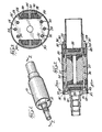
- FIG. 1 An assembled rotor 10 incorporating a cylindrical can 12 is illustrated in Fig. 1 and is exemplary of a structure with which the invention is operable.
- the basic rotor structure is shown clearly in Fig. 2 and comprises generally a main core 14, core winding end turn supports 16, 18 mounted at the axial ends of the core 14 and end shaft fittings 20, 22 mounted in turn to the end supports.
- the core subassembly, to include the core 14, end supports 16, 18 and end shaft fittings 20, 22 is held together by axially extending long and short bolts, respectively 24 and 26.
- the arrangement of elements illustrated facilitates sequential buildup from the core 14.
- the short bolts 26 extend from opposite ends of the end supports, threadably into the core 14. Each short bolt 26 extends through its respective end support 16, 18, entirely through the core 14 and into the opposite end support 16, 18 so as to prevent relative rotational movement between the end turn supports and the core.
- the end shaft fittings 20, 22 are mated with the ends of the end supports . 16, 18.
- At least two long bolts 24 extend axially and oppositely with each bolt 24 extending through its respective end shaft fitting 20, 22, the adjacent end turn support 16,18, through the core 14 and through the spaced end turn support and into the opposite end shaft fitting.
- the bolts 24, 26 and receiving bores 27 are machined to close tolerances.
- the bolts are precision ground, high strength, high permeability bolts which become part of the final assembly. As a result, the air gaps are minimal as is the disruption of the magnetic field from the connecting bolts.
- oppositely opening recesses 28 (Figs. 3 and 5) are provided within each of which an axially extending M-shaped wedge 30 is inserted.
- the wedge at each side of the core 14 defines, in conjunction with the core 14, spaced passageways 32 which accommodate the field windings 33.
- the outer surface 34 of the wedge 30 is contoured to define with the peripheral surface 35 of the core 14 a substantially cylindrical shape.
- the core and wedges may be machined after assembly to achieve the desired tolerances.
- the can 12 After completion of the core subassembly, the can 12 is assembled.
- the can 12 has an axial extent sufficient to overlap a portion of each end shaft fitting 20, 22.
- the free edges 36 of the can 12 will mate flushly at one end with a shoulder 38 defined by a stepped arrangement on the one end shaft fitting 22 and an oppositely and axially facing edge 40 formed by an annular ring 42 integral with the end shaft fitting 20 and coaxially aligned with the rotational axis of the rotor.
- the can is welded as at 37 adjacent its edges 36 with the annular ring 42 and the outer rim 44 defining the shoulder 38 to fix the can 12.
- an annular weld relief 43 is formed in the ring 42 and rim 44.
- each relief 48 in each of the end turn supports 16, 18 about the entire periphery thereof.
- the cross-section of each relief is preferably square or rectangular but may take any other desired configuration and may vary depending on the particular cutting tool contemplated.
- each wedge 30 is contoured to be centered in its respective recess 28 so that two separate reliefs 50 are defined by each wedge for the reasons advanced below.
- the wedges 30 are joined with the core 14 in conventional manner.
- Removal of the can 12 from the rotor subassembly is accomplished by cutting through the cam along the extent of the annular and axial reliefs.
- the edge of the cutting tool which is conventional, pierces the can and extends into the reliefs. The cutting edge will not contact any of the wedge, core or end turn supports.
- the preferred pattern of cuts is shown clearly in Fig. 4. Once this is accomplished, a plurality of access sections 58 are formed. The access sections all extend through an arc less than 180° so that the sections are readily separable from the core subassembly without having to deform the same.
- the location of the annular cuts is chosen to be spaced axially inwardly toward the center of the core from the point of welds 37 so that the welds 37 will not inhibit removal of any of the sections 58. With the section 58 removed, disassembly of the core subassembly may take place and all components, other than the end shaft fittings 20, 22 are ready for replacement or re-use, as the case may be.
- the remaining can fragments and weld material is removed from the end shaft fittings by machining. Because the end shaft fittings are cylindrical and coaxially aligned with the rotational axis of the rotor, machining of the weld material can be easily accomplished. With the can removed, refurbishment or repair of the rotor can proceed. After reworking, a new can may be reattached to the core subassembly.
Landscapes
- Engineering & Computer Science (AREA)
- Power Engineering (AREA)
- Manufacturing & Machinery (AREA)
- Manufacture Of Motors, Generators (AREA)
Abstract
Description
- This invention relates to rotors for use in electrical generators and more particularly to a method of removing the rotor encasement for refurbishment of the rotor.
- To enhance the structural integrity of a rotor and provide a structure suitable for high speed operation, the rotor core assembly is generally encased by a rigid, protective can. The can, which conforms to the peripheral surface of the core, is generally interference fit with the core and joined as by welding.
- The principal drawback with this particular construction is that the can becomes a permanent part of the rotor assembly and cannot be removed without damaging other parts of the rotor. Any minor defect in any portion of the rotor contained by the can renders the entire structure unusable. Rotor refurbishment is thus precluded and potentially reusable components of the rotor may be disposed of before their useful life is completed.
- The present invention is directed to overcoming the above problem.
- Two different aspects of the present invention are defined by
claims 1 and 6. The invention resides in the provision of reliefs in the core of a rotor typically having an overall cylindrical configuration. A cylindrical can is disposed over the core and overlies the reliefs and is welded or otherwise suitably affixed to the core. - Removal of the can is accomplished by cutting the can along the reliefs with the reliefs permitting extension of a cutting edge entirely through the can without contacting the core. A removable section is thus defined in the can, permitting access to the core. The remainder of the can is removable by a conventional machining operation.
- In a highly preferred form, axially spaced, annular reliefs are provided in the rotor assembly and are joined by at least two axially extending reliefs. The can is cut along the extent of the reliefs to define at least two readily separable access sections.
- By facilitating removal of the can from the core assembly, reworking of the rotor elements is made possible and the useful life of the rotor thereby prolonged. Further, neither the structural integrity nor the effectiveness of the rotor are compromised.
-
- Fig. 1 is a perspective view of a rotor incorporating a cylindrical protective can and embodying the invention;
- Fig. 2 is a sectional view of the rotor taken along line 2-2 of Fig. 1 and illustrating spaced annular reliefs according to the invention;
- Fig. 3 is a sectional view of the rotor taken along line 3-3 of Fig. 2 and illustrating axial reliefs according to the invention;
- Fig. 4 is a perspective view of the rotor in Fig. 1 with the can cut along the axial and annular reliefs;
- Fig. 5 is an exploded perspective view of the rotor in Fig. 4 with the can separated from the rotor core.
- An assembled
rotor 10 incorporating a cylindrical can 12 is illustrated in Fig. 1 and is exemplary of a structure with which the invention is operable. The basic rotor structure is shown clearly in Fig. 2 and comprises generally amain core 14, core winding end turn supports 16, 18 mounted at the axial ends of thecore 14 andend shaft fittings core 14, end supports 16, 18 andend shaft fittings - The arrangement of elements illustrated facilitates sequential buildup from the
core 14. Theshort bolts 26 extend from opposite ends of the end supports, threadably into thecore 14. Eachshort bolt 26 extends through itsrespective end support core 14 and into theopposite end support end shaft fittings long bolts 24 extend axially and oppositely with eachbolt 24 extending through its respective end shaft fitting 20, 22, the adjacentend turn support core 14 and through the spaced end turn support and into the opposite end shaft fitting. - The
bolts bores 27 are machined to close tolerances. The bolts are precision ground, high strength, high permeability bolts which become part of the final assembly. As a result, the air gaps are minimal as is the disruption of the magnetic field from the connecting bolts. - To accommodate field windings, oppositely opening recesses 28 (Figs. 3 and 5) are provided within each of which an axially extending M-
shaped wedge 30 is inserted. The wedge at each side of thecore 14 defines, in conjunction with thecore 14, spacedpassageways 32 which accommodate thefield windings 33. Theouter surface 34 of thewedge 30 is contoured to define with the peripheral surface 35 of the core 14 a substantially cylindrical shape. The core and wedges may be machined after assembly to achieve the desired tolerances. - After completion of the core subassembly, the can 12 is assembled. The can 12 has an axial extent sufficient to overlap a portion of each end shaft fitting 20, 22. Preferably, the
free edges 36 of the can 12 will mate flushly at one end with ashoulder 38 defined by a stepped arrangement on the one end shaft fitting 22 and an oppositely and axially facingedge 40 formed by anannular ring 42 integral with the end shaft fitting 20 and coaxially aligned with the rotational axis of the rotor. The can is welded as at 37 adjacent itsedges 36 with theannular ring 42 and the outer rim 44 defining theshoulder 38 to fix the can 12. To assure a precision weld, anannular weld relief 43 is formed in thering 42 and rim 44. - The invention resides in part in the provision of an
annular relief 48 in each of the end turn supports 16, 18 about the entire periphery thereof. The cross-section of each relief, as seen in Fig. 2, is preferably square or rectangular but may take any other desired configuration and may vary depending on the particular cutting tool contemplated. - To complement the
annular reliefs 48, longitudinally extendingreliefs 50 are defined between thewedges 30 and thecore 14 as seen most clearly in Figs. 3-5 and extend uninterrupted between theend shaft fittings core 14 takes a substantially I shape with thecross bars 52 of the I defined by the oppositely openingrecesses 28. The spacing between theouter legs 54 of eachwedge 30 is slightly less than the distance between theflat surfaces 56 under eachcross bar 52. Thereliefs 50 are defined by the gap between thelegs 54 and thecross bars 52. Preferably, eachwedge 30 is contoured to be centered in itsrespective recess 28 so that twoseparate reliefs 50 are defined by each wedge for the reasons advanced below. Thewedges 30 are joined with thecore 14 in conventional manner. - Removal of the can 12 from the rotor subassembly is accomplished by cutting through the cam along the extent of the annular and axial reliefs. The edge of the cutting tool, which is conventional, pierces the can and extends into the reliefs. The cutting edge will not contact any of the wedge, core or end turn supports. The preferred pattern of cuts is shown clearly in Fig. 4. Once this is accomplished, a plurality of
access sections 58 are formed. The access sections all extend through an arc less than 180° so that the sections are readily separable from the core subassembly without having to deform the same. The location of the annular cuts is chosen to be spaced axially inwardly toward the center of the core from the point ofwelds 37 so that thewelds 37 will not inhibit removal of any of thesections 58. With thesection 58 removed, disassembly of the core subassembly may take place and all components, other than theend shaft fittings - To enable reuse of the
end shaft fittings
Claims (9)
Applications Claiming Priority (2)
| Application Number | Priority Date | Filing Date | Title |
|---|---|---|---|
| US06/523,923 US4510679A (en) | 1983-08-17 | 1983-08-17 | Method of refurbishing a high speed rotor |
| US523923 | 2000-03-09 |
Publications (3)
| Publication Number | Publication Date |
|---|---|
| EP0153330A1 EP0153330A1 (en) | 1985-09-04 |
| EP0153330A4 EP0153330A4 (en) | 1985-12-30 |
| EP0153330B1 true EP0153330B1 (en) | 1987-10-07 |
Family
ID=24086985
Family Applications (1)
| Application Number | Title | Priority Date | Filing Date |
|---|---|---|---|
| EP19840902756 Expired EP0153330B1 (en) | 1983-08-17 | 1984-07-06 | High speed rotor and method of refurbishment |
Country Status (10)
| Country | Link |
|---|---|
| US (1) | US4510679A (en) |
| EP (1) | EP0153330B1 (en) |
| JP (1) | JPS60502083A (en) |
| CA (1) | CA1231366A (en) |
| DE (1) | DE3490385T1 (en) |
| GB (1) | GB2154160B (en) |
| IL (1) | IL72328A (en) |
| IT (1) | IT1178121B (en) |
| SG (1) | SG43787G (en) |
| WO (1) | WO1985000938A1 (en) |
Families Citing this family (27)
| Publication number | Priority date | Publication date | Assignee | Title |
|---|---|---|---|---|
| US4633113A (en) * | 1985-10-16 | 1986-12-30 | Sundstrand Corporation | Side plate construction for permanent magnet rotor |
| US5237737A (en) * | 1988-06-08 | 1993-08-24 | General Electric Company | Method of making a permanent magnet rotor |
| US5563463A (en) * | 1988-06-08 | 1996-10-08 | General Electric Company | Permanent magnet rotor |
| US5040286A (en) * | 1988-06-08 | 1991-08-20 | General Electric Company | Method for making permanent magnet rotor |
| US5144735A (en) * | 1988-06-08 | 1992-09-08 | General Electric Company | Apparatus for assembling a permanent magnet rotor |
| US5345669A (en) * | 1988-06-08 | 1994-09-13 | General Electric Company | Method of making a permanent magnet rotor |
| US4999533A (en) * | 1989-09-07 | 1991-03-12 | A. O. Smith Corporation | Dynamoelectric machine |
| US5881448A (en) * | 1992-04-06 | 1999-03-16 | General Electric Company | Method for making permanent magnet rotor |
| US6348752B1 (en) * | 1992-04-06 | 2002-02-19 | General Electric Company | Integral motor and control |
| US5325009A (en) * | 1993-05-07 | 1994-06-28 | Sundstrand Corporation | Rotor shaft with integral wedge retainers for core of a two-pole generator |
| US5323080A (en) * | 1993-05-07 | 1994-06-21 | Sundstrand Corporation | One-piece rotor shaft for two-pole rotor |
| JP2941191B2 (en) * | 1994-07-25 | 1999-08-25 | 日本碍子株式会社 | Method and apparatus for peeling off outer cylinder of waste NaS battery |
| DE19935723B4 (en) * | 1999-04-19 | 2009-12-31 | Dietz-Motoren Gmbh & Co. Kg | Method for producing an electric motor arrangement |
| US6727634B2 (en) | 2001-08-30 | 2004-04-27 | Honeywell International, Inc. | System and method for end turn retention on a high speed generator rotor |
| US6859019B2 (en) | 2001-08-30 | 2005-02-22 | Honeywell International, Inc. | System and method for coupling rectifiers of an exciter to the rotor of a main generator |
| US6753637B2 (en) | 2001-09-07 | 2004-06-22 | Honeywell International, Inc. | Exciter rotor assembly |
| US6791230B2 (en) | 2001-09-07 | 2004-09-14 | Honeywell International, Inc. | System and method for retaining wedges in a rotor |
| US6734585B2 (en) | 2001-11-16 | 2004-05-11 | Honeywell International, Inc. | Rotor end caps and a method of cooling a high speed generator |
| JP2005328601A (en) * | 2004-05-13 | 2005-11-24 | Minebea Co Ltd | Tubular motor for electric shutter or blind |
| US20070234555A1 (en) * | 2006-04-06 | 2007-10-11 | Cardianove Inc. | Rotor assembly fixture for magnet magnetization |
| US8084902B2 (en) * | 2009-05-06 | 2011-12-27 | Hamilton Sundstrand Corporation | End plates for high speed generator applications |
| US20110080068A1 (en) * | 2009-10-06 | 2011-04-07 | General Electric Company | Laminated generator rotor structure and related method |
| WO2013006079A1 (en) | 2011-07-06 | 2013-01-10 | General Electric Company | Laminated rotor machining enhancement |
| US10038356B2 (en) * | 2012-05-22 | 2018-07-31 | General Electric Company | Generator rotor refurbishing system and method of repairing a generator rotor |
| US8959767B2 (en) | 2012-11-21 | 2015-02-24 | United Technologies Corporation | Method of extending life of rotating parts |
| US10177618B2 (en) * | 2016-03-15 | 2019-01-08 | General Atomics | Rotor assembly and method of manufacturing |
| PL4195457T3 (en) * | 2021-12-10 | 2026-04-20 | Ge Energy Power Conversion Technology Ltd | System comprising a rotor and bearings and associated method |
Family Cites Families (6)
| Publication number | Priority date | Publication date | Assignee | Title |
|---|---|---|---|---|
| US1233591A (en) * | 1915-09-24 | 1917-07-17 | James Lloyd Macfarlane | Textile spinner and twister. |
| GB386931A (en) * | 1931-11-05 | 1933-01-26 | Bbc Brown Boveri & Cie | Improvements in and relating to rotors |
| US2994795A (en) * | 1957-03-21 | 1961-08-01 | Westinghouse Electric Corp | Construction for dynamoelectric machine |
| NL251206A (en) * | 1959-05-04 | 1900-01-01 | ||
| US3138105A (en) * | 1961-02-08 | 1964-06-23 | Fostoria Corp | Motor driven pumps |
| SE395991B (en) * | 1975-12-17 | 1977-08-29 | Asea Ab | ROTOR FOR TURBO GENERATOR |
-
1983
- 1983-08-17 US US06/523,923 patent/US4510679A/en not_active Expired - Fee Related
-
1984
- 1984-07-06 JP JP59502714A patent/JPS60502083A/en active Pending
- 1984-07-06 WO PCT/US1984/001063 patent/WO1985000938A1/en not_active Ceased
- 1984-07-06 GB GB8508483A patent/GB2154160B/en not_active Expired
- 1984-07-06 IL IL7232884A patent/IL72328A/en unknown
- 1984-07-06 DE DE19843490385 patent/DE3490385T1/en not_active Withdrawn
- 1984-07-06 EP EP19840902756 patent/EP0153330B1/en not_active Expired
- 1984-07-12 CA CA000458774A patent/CA1231366A/en not_active Expired
- 1984-08-10 IT IT4871884A patent/IT1178121B/en active
-
1987
- 1987-05-13 SG SG43787A patent/SG43787G/en unknown
Also Published As
| Publication number | Publication date |
|---|---|
| IT8448718A0 (en) | 1984-08-10 |
| EP0153330A4 (en) | 1985-12-30 |
| GB8508483D0 (en) | 1985-05-09 |
| JPS60502083A (en) | 1985-11-28 |
| US4510679A (en) | 1985-04-16 |
| GB2154160B (en) | 1986-12-31 |
| EP0153330A1 (en) | 1985-09-04 |
| CA1231366A (en) | 1988-01-12 |
| WO1985000938A1 (en) | 1985-02-28 |
| IL72328A (en) | 1988-06-30 |
| IT8448718A1 (en) | 1986-02-10 |
| IT1178121B (en) | 1987-09-09 |
| GB2154160A (en) | 1985-09-04 |
| SG43787G (en) | 1987-07-17 |
| DE3490385T1 (en) | 1985-11-28 |
| IL72328A0 (en) | 1984-11-30 |
Similar Documents
| Publication | Publication Date | Title |
|---|---|---|
| US4510679A (en) | Method of refurbishing a high speed rotor | |
| US4598218A (en) | High speed rotor with removable can | |
| EP0153324B1 (en) | Method of assembly of a rotor | |
| US4614888A (en) | Improved magnetic rotor | |
| US4064410A (en) | Squirrel cage rotor and method of making same | |
| CA1298342C (en) | Dynamoelectric machine stator using cylindrical keybar with improved dovetail configuration | |
| EP0223612B1 (en) | Electrical machine rotor | |
| EP0708877B1 (en) | Method for repairing a combustion chamber assembly | |
| US4564779A (en) | Dynamoelectric machine stator using cylindrical keybars | |
| KR101605412B1 (en) | Method of servicing a power generator | |
| KR20140133543A (en) | Turbine generator stator core attachment technique | |
| CA1155161A (en) | Ducted cast rotor and method of making same | |
| US5467521A (en) | Method of producing squirrel-cage rotor for induction motor | |
| US4570517A (en) | Self-interlocking split saw blade | |
| JPH10336929A (en) | Rotor of rotary magnet motor and method of manufacturing the same | |
| US20210099037A1 (en) | Wound-type rotor for a synchronous electric machine | |
| CZ174796A3 (en) | Electric machine, particularly alternating current generator | |
| EP0684683B1 (en) | Stator frame and method of manufacturing it | |
| JPH09234626A (en) | Cutter body of single parts | |
| US2235807A (en) | Electric motor frame construction | |
| JPH0333381Y2 (en) | ||
| JPH07131946A (en) | Rotor for alternator | |
| US10903717B2 (en) | Repaired rotor of a multi-phase electric motor and method of repair | |
| GB2037093A (en) | Stator assemblies for electrical rotating machines | |
| JPS6019225B2 (en) | Manufacturing method of single-pole inductor motor |
Legal Events
| Date | Code | Title | Description |
|---|---|---|---|
| PUAI | Public reference made under article 153(3) epc to a published international application that has entered the european phase |
Free format text: ORIGINAL CODE: 0009012 |
|
| 17P | Request for examination filed |
Effective date: 19850410 |
|
| AK | Designated contracting states |
Designated state(s): FR |
|
| RIN1 | Information on inventor provided before grant (corrected) |
Inventor name: WEFEL, JERRY, D. Inventor name: LOBSINGER, JAMES, L. Inventor name: ALEEM, MOHD, A. |
|
| 17Q | First examination report despatched |
Effective date: 19861030 |
|
| GRAA | (expected) grant |
Free format text: ORIGINAL CODE: 0009210 |
|
| AK | Designated contracting states |
Kind code of ref document: B1 Designated state(s): FR |
|
| ET | Fr: translation filed | ||
| PLBE | No opposition filed within time limit |
Free format text: ORIGINAL CODE: 0009261 |
|
| STAA | Information on the status of an ep patent application or granted ep patent |
Free format text: STATUS: NO OPPOSITION FILED WITHIN TIME LIMIT |
|
| 26N | No opposition filed | ||
| PGFP | Annual fee paid to national office [announced via postgrant information from national office to epo] |
Ref country code: FR Payment date: 19890707 Year of fee payment: 6 |
|
| PG25 | Lapsed in a contracting state [announced via postgrant information from national office to epo] |
Ref country code: FR Effective date: 19910329 |
|
| REG | Reference to a national code |
Ref country code: FR Ref legal event code: ST |