EP0153148A1 - Apparatus for producing cooked meat slices - Google Patents
Apparatus for producing cooked meat slices Download PDFInfo
- Publication number
- EP0153148A1 EP0153148A1 EP85300967A EP85300967A EP0153148A1 EP 0153148 A1 EP0153148 A1 EP 0153148A1 EP 85300967 A EP85300967 A EP 85300967A EP 85300967 A EP85300967 A EP 85300967A EP 0153148 A1 EP0153148 A1 EP 0153148A1
- Authority
- EP
- European Patent Office
- Prior art keywords
- spit
- meat
- knife
- cylinder
- grill
- Prior art date
- Legal status (The legal status is an assumption and is not a legal conclusion. Google has not performed a legal analysis and makes no representation as to the accuracy of the status listed.)
- Withdrawn
Links
Images


Classifications
-
- B—PERFORMING OPERATIONS; TRANSPORTING
- B26—HAND CUTTING TOOLS; CUTTING; SEVERING
- B26D—CUTTING; DETAILS COMMON TO MACHINES FOR PERFORATING, PUNCHING, CUTTING-OUT, STAMPING-OUT OR SEVERING
- B26D3/00—Cutting work characterised by the nature of the cut made; Apparatus therefor
- B26D3/10—Making cuts of other than simple rectilinear form
- B26D3/11—Making cuts of other than simple rectilinear form to obtain pieces of spiral or helical form
-
- A—HUMAN NECESSITIES
- A47—FURNITURE; DOMESTIC ARTICLES OR APPLIANCES; COFFEE MILLS; SPICE MILLS; SUCTION CLEANERS IN GENERAL
- A47J—KITCHEN EQUIPMENT; COFFEE MILLS; SPICE MILLS; APPARATUS FOR MAKING BEVERAGES
- A47J37/00—Baking; Roasting; Grilling; Frying
- A47J37/04—Roasting apparatus with movably-mounted food supports or with movable heating implements; Spits
- A47J37/043—Roasting apparatus with movably-mounted food supports or with movable heating implements; Spits with food supports rotating about a vertical axis
Definitions
- the invention is an apparatus for producing cooked meat in the form of slices. It is of particular value and interest for producing sliced cooked meat suitable for use in döner kebabs.
- the thickness of the sliced meat, and consequently the uniformity of the product quality may vary excessively and a less acceptable product is obtained.
- a further disadvantage of the conventional method of producing doner kebab slices is that, because the grilling and slicing are carried out as a continuous operation, it is necessary for the operative, when slicing the meat from The loaf, to stand uncomfortably close to the grill.
- the apparatus according to the present invention for producing cooked meat slices comprises a rotary spit adapted to receive a cylinder of meat and rotate it about its axis, a grill adjacent to and facing said spit and extending over at least the approximate axial extent thereof so as to grill the curved surface of such meat cylinder, knife means mounted to remove slices of meat from the cylinder surface as the spit rotates, and advancing means to achieve progressive relative approach of the spit and the knife means as meat is removed from the cylinder surface.
- the rotary spit itself may be of conventional design.
- the spit In the case of döner kebab production, the spit is normally vertical, the drive to rotate the spit being located at the lower end thereof and the whole spit and meat loaf assembly being demountable when a fresh supply of meat is required.
- the rotational speed of the spit is preferably variable, to take account of different rates of cooking of the meat and also of different rates of removal of meat slices according to demand.
- the grill may be heated by any desired method but in particular by gas or electricity.
- a control for the rate of heat output of the grill is preferably provided.
- the grill may comprise a flat or curved array of heating elementsand may be one or more grill units, for example two such flat or curved arrays set at an angle to each other.
- the frill should extend, in the axial direction of the spit, at least sufficiently far to irradiate the full length of the meat loaf.
- the knife means which is an essential feature of the present invention may be a flat, preferably elongated blade and may function with its cutting edge parallel to the axis of the spit (that is vertically when the spit is vertical) but preferably the cutting edge extends generally tangentially with respect to said axis and to the curved surface of the cylindrical meat loaf. In this latter orientation, the knife means removes a meat slice in a direction parallel to the axis.
- the knife means is vibrated or otherwise reciprocated parallel to its cutting edge so as to assist cutting.
- Progression of the knife means over the surface of the meat loaf as it cuts a slice may be acHeved by mounting the knife means on a screw-threaded shaft and rotating the latter.
- the cutting blade may, if desired, be double-edged so as to cut also on a return stroke.
- the blade may cut in one direction of movement only and then return to its starting position, from where it may begin a new cutting stroke, if desired after a pause related to the rate of rotation of the spit.
- the return of the blade may be achieved either by reversing the blade drive means, e.g. an electric motor, or by providing a reversing transmission between the drive means and the blade.
- orientation of the knife means in which the cutting edge is parallel to the axis of the loaf, it is not necessary to move the knife means to cut a slice as the relative movement is provided by rotation of the meat loaf.
- advancing means are provided to achieve progressive relative approach of the spit and the knife means as meat is removed from the cylindrical surface of the meat loaf.
- This progressive approach may be achieved by movement of either the spit or the knife means or of both.
- the knife means which moves towards the spit.
- the advancing means may, at its simplest, be manually operated means such that the operative adjusts the position of the knife means as necessary. However, it is much preferred that the advancing means be automatic.
- Such an automatic advancing means may respond to a mechanical or electrical signal, for example from a feeler, whichindicates the actual or relative diameter of the meat loaf at any given moment.
- the advancing means may be controlled by signals derived from factors which determine the rate of removal of meat from the loaf, for example the rate of rotation of the spit and/or the rate of progress of the knife means over the meat surface (the cutting rate).
- the rate of automatic relative approach of the knife means and the spit may be related to the observed rate of removal of meat or to the calculated rate of removal of meat on a "dead reckoning" basis.
- the knife means may move towards the axis of the spit along a linear path or, alternatively and preferably, along an arcuate path.
- the grill may also be moved closer to the axis of the spit as the meat is removed.
- the movement of the grill may be linked directly, either mechanically or electrically, to the advancing of the knife means or may be operated independently thereof.
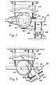
- the illustrated embodiment comprises a substantially vertical rod or spit 10 connected by a quick-action coupling 12 to a stub 14 jounalled near its bottom end by a bearing 16 in a horizontal member 18 of a supporting frame indicated generally by the numeral 20.
- the rod or spit 10 is located relative to a trunnion 22 aligned with the stub 14, by means of a manually-shiftable sleeve 24.
- this additional support for the spit, in the form of trunnion 22 and sleeve 24 may be omitted if desired.
- the stub 14 carries a pulley 26 enabling it to be driven, for instance at a rate of 0.1 to 0.5 revolutions per minute, from an electric motor 28 mounted on the frame 20.
- the function of the rod or spit 10 is to support a meat cylinder 30, for example formed by compression of minced and/or otherwise processed meat, the axial height of the cylinder being, for example, in the range of 600 to 800 mms. and the diameter thereof being, for instanc in the range of 400 to 700 mms.
- a cooking Trill indicated diagrammatically at 32 is arranged behind the rod or spit 10 so as to be approximately arcuately disposed behind the meat cylinder 30, over the entire height thereof, and, as is illustrated in Fig. 2, the frill 32 is carried by a crosspiece 34 (omitted from Fig. 1 for simplification of illustration) guided for movement towards and away from the meat cylinder 30 by a smooth guide rod 36 and a parallel threaded guide rod 38 both of which are supported by the frame 20.
- the threaded guide rod 38 is rotatable, is provided with a gearwheel 40 on its end adjacent to the horizontal frame member 18 and engages with the cross piece 34 so that upon rotation of the rod 38 the crosspiece 34 approaches towards or recedes from the cylinder 30.
- the rod 38 accordingly serves as a traverse screw and is adapted to be rotated, at a rate correlated to the rate of rotation of the cylinder 30 and the thicknesses of the slices desired to be cut, by a respective motor (not shown) embodied in the crosspiece 34.
- a gearwheel 50 on the threaded rod 44 meshes with the gearwheel 40 so the two traverse screws 38 and 44 rotate in unison and progress their respective crosspieces 34 and 46 simultaneously either towards or away from the cylinder 30 at equal speeds.
- the rod 52 is Carried by the crosspiece 46 are parallel feed guide rods 52 and 54 of which the rod 52 is a feed screw driven by a feed motor 56 supported below the crosspiece 46.
- the rods 52, 54 serve to guide a knife-carrying housing 58 with which the feed screw 52 threadedly enrages and which supports a horizontal cutting blade 60.
- Incorporated in the housing 58 is a vibrator by means of which the blade 60 is vibrated.
- a receiver in the form of a heated receptacle is provided beneath the frame 20 in a position to receive meat slices severed from the cylinder 30 by means of the blade 60.
- this first form of apparatus With the motor in the crosspiece 34 and the motors 28 and 56 running, and with the grill 32 operative, the cylinder 30 rotates slowly and its surface facing the grill 32 is cooked to a depth of about 2 mm. upon one pass before the grill. Simultaneously, the knife blade 60 cuts a continuous strip- form slice from the cylinder 50, this being for instance of 1 to 2 mm. in thickness.
- the knife carrier 58 is, of course. caused (by the operation of the motor 56) to be fed up and down the cylinder 30 at a relatively rapid rate so that the slices it cuts are of relatively wide strip-like configuration.
- the vibration of the blade 60 serves to ensure effective severing by the knife blade 60. As previously mentioned, the cut slices fall into the receptacle below the knife, for subsequent collection.
- the two traverse screws 38 and 44 rotate to approach the knife blade 60 and the grill 32 towards the surface of the cylinder 30, thereby to maintain a consiant spacing of the grill 32 from the cylinder 30 and a constant slicing thickness.
- Fig. 3 The embodiment of Fig. 3 is in general similar to that described above and operates in the same manner. It differs from the preceding embodiment, however, in that the crosspiece 34 is slidable along two smooth guide rods 36 and the traverse screw 38 extends through the frame member 18 to terminate at a bevel gear 40a. This enables the traverse screw 44, provided with a bevel rear 50a, and its associated guide rod 42 to be disposed at an angle to the guide rods 36.
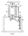
- Figs. 4 and 5 of the drawings represents a preferred form of the present invention.
- the cylindrical meat loaf 30 is similarly supported by a spit 10, mounted and driven in the same way as in the apparatus of Figs. 1 to 3.
- the arrangements for progressing the knife over the loaf surface and for advancing the knife and the grill towards the spit are all different from those of the other embodiments.
- the knife blade 60 is supported by a knife-carrying housing 62, which incorporates means for vibrating the blade 60 and which in turn is carried at the upper end of a hollow rod 64.
- the rod 64 extends through a bore 66 in the member 18 and is supported below that member upon a vertical stub 68 on the mounting 70 of a reversing motor 72.
- the motor 72 runs vertically upon a threaded rotary shaft 74 and, in traversing the length of the shaft 74 in a vertically downward direction, cuts a continuous or discontinuous slice of meat from the cylinder 30. When the motor 72 reaches the bottom of the shaft 74, it reverses its linear direction of movement and climbs to the top of the shaft to begin the next cutting stroke of the knife blade 60.
- the knife vlade 60 is free to swing towards the axis of the cylinder 30. This swinging movement is effect by the operation of a stepping linear actuator (not shown) upon a rod 76, extending radially from the lower end of the hollow rod 64 and to which the actuator shaft is ! directly coupled.
- the grill is in two sections 80 and 82, pivoted at 80a and 82a respectively. Pivotal movement of the grill sections towards the meat cylinder 30 is effected by means of a drive chain working in opposite directions around chain wheels below the respective pivot points, against the pressure of a chain-return spring.
- drive means other than a chain drive may be used to secure pivoting of the grill sections.
- the various drive motors for giving the linear vertical motion of the knife blade 60 and for advancing the knife blade 60 and grill sections 80, 82 towards the meat cylinder are individually controlled by a microprocessor, which in turn determines the aforesaid operations in response to input information regarding, in particular, the rate of rotation of the spit and the rate of removal of meat from the cylinder 30.
Abstract
Apparatus for producing cooked meat in the form of slices, for example for slicing meat for d6ner kebabs, comprises a rotary spit (10) to receive a cylinder of meat (30) and rotate it about its axis, a grill (32 or 80, 82) adjacent to and facing the spit (10) and extending over at least the approximate axial extent thereof so as to grill the curved surface of the meat cylinder, knife means (60) to remove slices of meat from the cylinder surface as the spit rotates and advancing means (44 or a stepping linear actuator) to achieve progressive relative approach of the spit (10) and the knife means (60) as meat is removed from the cylinder surface.
Description
- The invention is an apparatus for producing cooked meat in the form of slices. It is of particular value and interest for producing sliced cooked meat suitable for use in döner kebabs.
- In the conventional production of döner kebabs, a large cylindrical loaf of compressed meat is cooked on a vertical spit rotating in front of a grill adjacent to the serving counter and slices of meat are cut from the surface of the meat loaf as required. The satisfactory cutting of the meat from the loaf is a skilled operation and reauires a disproportionate amount of the time of an experienced operative. Since the operation is usually carried out in a fast-food establishment, where it is essential that all activities be carried out competitively, it is highly desirable that the level of skill and time entailed should be reduced to a minimum.
- If, however, a less skilled operative is employed, then the thickness of the sliced meat, and consequently the uniformity of the product quality, may vary excessively and a less acceptable product is obtained.
- A further disadvantage of the conventional method of producing doner kebab slices is that, because the grilling and slicing are carried out as a continuous operation, it is necessary for the operative, when slicing the meat from The loaf, to stand uncomfortably close to the grill.
- With the aforesaid disadvantages in mind, it is an important object of the present invention to provide an apparatus fcr producing cooked meat slices which is less dependent on the skill of the operative, uses less of the operative's time and in turn reduces the operative's exposure to the heat of the frill, while making it possible to maintain the uniformity of quality of the sliced, cooked meat.
- The apparatus according to the present invention for producing cooked meat slices comprises a rotary spit adapted to receive a cylinder of meat and rotate it about its axis, a grill adjacent to and facing said spit and extending over at least the approximate axial extent thereof so as to grill the curved surface of such meat cylinder, knife means mounted to remove slices of meat from the cylinder surface as the spit rotates, and advancing means to achieve progressive relative approach of the spit and the knife means as meat is removed from the cylinder surface.
- The rotary spit itself may be of conventional design. In the case of döner kebab production, the spit is normally vertical, the drive to rotate the spit being located at the lower end thereof and the whole spit and meat loaf assembly being demountable when a fresh supply of meat is required. The rotational speed of the spit is preferably variable, to take account of different rates of cooking of the meat and also of different rates of removal of meat slices according to demand.
- The grill may be heated by any desired method but in particular by gas or electricity. A control for the rate of heat output of the grill is preferably provided. The grill may comprise a flat or curved array of heating elementsand may be one or more grill units, for example two such flat or curved arrays set at an angle to each other. To ensure complete cooking of the meat loaf,the frill should extend, in the axial direction of the spit, at least sufficiently far to irradiate the full length of the meat loaf.
- The knife means which is an essential feature of the present invention may be a flat, preferably elongated blade and may function with its cutting edge parallel to the axis of the spit (that is vertically when the spit is vertical) but preferably the cutting edge extends generally tangentially with respect to said axis and to the curved surface of the cylindrical meat loaf. In this latter orientation, the knife means removes a meat slice in a direction parallel to the axis. Preferably the knife means is vibrated or otherwise reciprocated parallel to its cutting edge so as to assist cutting.
- Progression of the knife means over the surface of the meat loaf as it cuts a slice may be acHeved by mounting the knife means on a screw-threaded shaft and rotating the latter. In the case of a knife means which progresses in a direction parallel to the axis of the loaf, the cutting blade may, if desired, be double-edged so as to cut also on a return stroke. Alternatively, the blade may cut in one direction of movement only and then return to its starting position, from where it may begin a new cutting stroke, if desired after a pause related to the rate of rotation of the spit. In either case, the return of the blade may be achieved either by reversing the blade drive means, e.g. an electric motor, or by providing a reversing transmission between the drive means and the blade.
- In the alternative, less preferred, orientation of the knife means, in which the cutting edge is parallel to the axis of the loaf, it is not necessary to move the knife means to cut a slice as the relative movement is provided by rotation of the meat loaf.
- In the apparatus according to the present invention advancing means are provided to achieve progressive relative approach of the spit and the knife means as meat is removed from the cylindrical surface of the meat loaf. This progressive approach may be achieved by movement of either the spit or the knife means or of both. Preferably it is the knife means which moves towards the spit. The advancing means may, at its simplest, be manually operated means such that the operative adjusts the position of the knife means as necessary. However, it is much preferred that the advancing means be automatic.
- Such an automatic advancing means may respond to a mechanical or electrical signal, for example from a feeler, whichindicates the actual or relative diameter of the meat loaf at any given moment. Alternatively, the advancing means may be controlled by signals derived from factors which determine the rate of removal of meat from the loaf, for example the rate of rotation of the spit and/or the rate of progress of the knife means over the meat surface (the cutting rate). In other words, the rate of automatic relative approach of the knife means and the spit may be related to the observed rate of removal of meat or to the calculated rate of removal of meat on a "dead reckoning" basis.
- The knife means may move towards the axis of the spit along a linear path or, alternatively and preferably, along an arcuate path.
- As a further optional feature of the present invention, the grill may also be moved closer to the axis of the spit as the meat is removed. The movement of the grill may be linked directly, either mechanically or electrically, to the advancing of the knife means or may be operated independently thereof.
- The invention will now be further described, by way of example, with reference to the accompanying drawings, in which : -
- Fig. 1 is a diagrammatic part-sectional front view illustrating a first embodiment of the apparatus of the present invention;
- Fig. 2 is a diagrammatic part-sectional plan view of the apparatus of Fig. 1;
- Fig. 3 is a view corresponding to Fig. 2 but illustrating a second embodiment of the apparatus of the present invention;
- Fir. 4 is a diagrammatic part-sectional front view of a preferred third embodiment of the apparatus of the present invention; and
- Fig. 5 is a diagrammatic plan view of the apparatus of Fig. 4.
- Throughout the various figures of the drawings, similar reference numerals have been used to indicate similar parts.
- Referring firstly to Figs. 1 and 2, the illustrated embodiment comprises a substantially vertical rod or
spit 10 connected by a quick-action coupling 12 to astub 14 jounalled near its bottom end by abearing 16 in ahorizontal member 18 of a supporting frame indicated generally by thenumeral 20. At its upper end the rod orspit 10 is located relative to atrunnion 22 aligned with thestub 14, by means of a manually-shiftable sleeve 24. However this additional support for the spit, in the form oftrunnion 22 andsleeve 24, may be omitted if desired. - The
stub 14 carries apulley 26 enabling it to be driven, for instance at a rate of 0.1 to 0.5 revolutions per minute, from anelectric motor 28 mounted on theframe 20. - As seen in Figs. 1 and 2, the function of the rod or
spit 10 is to support ameat cylinder 30, for example formed by compression of minced and/or otherwise processed meat, the axial height of the cylinder being, for example, in the range of 600 to 800 mms. and the diameter thereof being, for instanc in the range of 400 to 700 mms. - A cooking Trill indicated diagrammatically at 32 is arranged behind the rod or
spit 10 so as to be approximately arcuately disposed behind themeat cylinder 30, over the entire height thereof, and, as is illustrated in Fig. 2, thefrill 32 is carried by a crosspiece 34 (omitted from Fig. 1 for simplification of illustration) guided for movement towards and away from themeat cylinder 30 by asmooth guide rod 36 and a parallel threadedguide rod 38 both of which are supported by theframe 20. The threadedguide rod 38 is rotatable, is provided with agearwheel 40 on its end adjacent to thehorizontal frame member 18 and engages with thecross piece 34 so that upon rotation of therod 38 thecrosspiece 34 approaches towards or recedes from thecylinder 30. Therod 38 accordingly serves as a traverse screw and is adapted to be rotated, at a rate correlated to the rate of rotation of thecylinder 30 and the thicknesses of the slices desired to be cut, by a respective motor (not shown) embodied in thecrosspiece 34. - At the side of the
cylinder 30 remote from thefrill 32 is a further pair ofguide rods guide rod 44 is threaded and serves as a traverse screw for arespective cross-piece 46 for a knife arrangement indicated generally by thenumeral 48. Agearwheel 50 on the threadedrod 44 meshes with thegearwheel 40 so the twotraverse screws respective crosspieces cylinder 30 at equal speeds. - Carried by the
crosspiece 46 are parallelfeed guide rods rod 52 is a feed screw driven by afeed motor 56 supported below thecrosspiece 46. Therods housing 58 with which the feed screw 52 threadedly enrages and which supports ahorizontal cutting blade 60. Incorporated in thehousing 58 is a vibrator by means of which theblade 60 is vibrated. - A receiver (not shown) in the form of a heated receptacle is provided beneath the
frame 20 in a position to receive meat slices severed from thecylinder 30 by means of theblade 60. - The manner of operation of this first form of apparatus will readily be understood from the foregoing description. With the motor in the
crosspiece 34 and themotors grill 32 operative, thecylinder 30 rotates slowly and its surface facing thegrill 32 is cooked to a depth of about 2 mm. upon one pass before the grill. Simultaneously, theknife blade 60 cuts a continuous strip- form slice from thecylinder 50, this being for instance of 1 to 2 mm. in thickness. Theknife carrier 58 is, of course. caused (by the operation of the motor 56) to be fed up and down thecylinder 30 at a relatively rapid rate so that the slices it cuts are of relatively wide strip-like configuration. The vibration of theblade 60 serves to ensure effective severing by theknife blade 60. As previously mentioned, the cut slices fall into the receptacle below the knife, for subsequent collection. - As the knife cuts the meat slices, and the effective diameter of the cylinder decreases, the two
traverse screws knife blade 60 and thegrill 32 towards the surface of thecylinder 30, thereby to maintain a consiant spacing of thegrill 32 from thecylinder 30 and a constant slicing thickness. - The embodiment of Fig. 3 is in general similar to that described above and operates in the same manner. It differs from the preceding embodiment, however, in that the
crosspiece 34 is slidable along twosmooth guide rods 36 and thetraverse screw 38 extends through theframe member 18 to terminate at a bevel gear 40a. This enables thetraverse screw 44, provided with a bevel rear 50a, and its associatedguide rod 42 to be disposed at an angle to theguide rods 36. - The embodiment illustrated in Figs. 4 and 5 of the drawings represents a preferred form of the present invention. In that embodiment, the
cylindrical meat loaf 30 is similarly supported by aspit 10, mounted and driven in the same way as in the apparatus of Figs. 1 to 3. However the arrangements for progressing the knife over the loaf surface and for advancing the knife and the grill towards the spit are all different from those of the other embodiments. - The
knife blade 60 is supported by a knife-carryinghousing 62, which incorporates means for vibrating theblade 60 and which in turn is carried at the upper end of ahollow rod 64. Therod 64 extends through abore 66 in themember 18 and is supported below that member upon avertical stub 68 on the mounting 70 of a reversingmotor 72. Themotor 72 runs vertically upon a threadedrotary shaft 74 and, in traversing the length of theshaft 74 in a vertically downward direction, cuts a continuous or discontinuous slice of meat from thecylinder 30. When themotor 72 reaches the bottom of theshaft 74, it reverses its linear direction of movement and climbs to the top of the shaft to begin the next cutting stroke of theknife blade 60. - Because the
rod 64 is freely rotatable about thestub 68, theknife vlade 60 is free to swing towards the axis of thecylinder 30. This swinging movement is effect by the operation of a stepping linear actuator (not shown) upon arod 76, extending radially from the lower end of thehollow rod 64 and to which the actuator shaft is ! directly coupled. - The grill is in two
sections meat cylinder 30 is effected by means of a drive chain working in opposite directions around chain wheels below the respective pivot points, against the pressure of a chain-return spring. Alternatively, drive means other than a chain drive may be used to secure pivoting of the grill sections. - The various drive motors for giving the linear vertical motion of the
knife blade 60 and for advancing theknife blade 60 andgrill sections cylinder 30.
Claims (12)
1. Apparatus for producing cooked meat slices, comprising a rotary spit adapted to receive a cylinder of meat and rotate it about its axis, a grill adjacent to and facing said spit and extending over at least the approximate axial extent thereof so as to grill the curved surface of such meat cylinder, knife means mounted to remove slices of meat from the cylinder surface as th.e spit rotates, and advancing means to achieve progressive relative approach of the spit and the knife means as meat is removed from the cylinder surface.
2. Apparatus as claimed in claim 1, having variable drive means to rotate the spit at different speeds.
3. Apparatus as claimed in claim 1 or claim 2, wherein the spit is mounted with its axis generally vertical and the knife means has a cutting edge extending parallel to the axis of the spit.
4. Apparatus as claimed in claim 1 or claim 2, wherein the spit is mounted with its axis generally vertical and the knife means has a cutting edge extending generally tangentially with respect to said axis.
5. Apparatus as claimed in claim 4, wherein the knife means is vibratable parallel to its cutting edge.
6. Apparatus as claimed in claim 4 or claim 5, having knife progressing means to move the knife means in a direction parallel to the axis of the spit.
7. Apparatus as claimed in claim 6, wherein the movement of the knife means parallel to the axis of the spit is reversible.
8. Apparatus as claimed in claim 6 or claim 7, wherein the knife progressing means is a rotary screw-threaded shaft.
9. Apparatus as claimed in any of the preceding claims, wherein the progressive relative approach of the spit and the knife means is attained by movement of the knife means.
10. Apparatus as claimed in claim 9, having also grill advancing means to move the grill progressively close to the spit as meat is removed from the cylinder surface.
11. Apparatus as claimed in any of the preceding claims wherein the extent of relative approach of the spit and the knife means is determined by monitoring the diameter of the meat cylinder.
12. Apparatus as claimed in any of claims 1 to 10, having a microprocessor to calculate the extent of removal of meat from the meat cylinder and thereby to instruct the knife means and/or the spit to relatively approach each other.
Applications Claiming Priority (2)
| Application Number | Priority Date | Filing Date | Title |
|---|---|---|---|
| GB848404352A GB8404352D0 (en) | 1984-02-18 | 1984-02-18 | Producing cooked meat slices |
| GB8404352 | 1984-02-18 |
Publications (1)
| Publication Number | Publication Date |
|---|---|
| EP0153148A1 true EP0153148A1 (en) | 1985-08-28 |
Family
ID=10556850
Family Applications (1)
| Application Number | Title | Priority Date | Filing Date |
|---|---|---|---|
| EP85300967A Withdrawn EP0153148A1 (en) | 1984-02-18 | 1985-02-14 | Apparatus for producing cooked meat slices |
Country Status (2)
| Country | Link |
|---|---|
| EP (1) | EP0153148A1 (en) |
| GB (1) | GB8404352D0 (en) |
Cited By (10)
| Publication number | Priority date | Publication date | Assignee | Title |
|---|---|---|---|---|
| US5437886A (en) * | 1990-03-28 | 1995-08-01 | Unilever Patent Holdings B.V. | Cutting process |
| DE19545699C1 (en) * | 1995-12-07 | 1997-05-22 | Tevfik Guel | Grill with a rotatable meat skewer |
| WO1999051135A1 (en) * | 1998-04-03 | 1999-10-14 | Ayhan Babacan | Integrated cooking and cutting instrument for fast food doner kebab and method therefor |
| GB2364893A (en) * | 2000-07-27 | 2002-02-13 | Hop Shing Metal & Plastic Manu | Electric knife with pivoting handle |
| WO2007070017A2 (en) * | 2005-12-15 | 2007-06-21 | Ayhan Babacan | Integrated cooking and cutting instrument for fast food doner kebab and method therefor |
| WO2009085022A1 (en) * | 2007-12-31 | 2009-07-09 | Güçtek Mühendislik Makina Insaat Elektronik Bilgisayar Sanayi Ticaret Limited Sirketi | Microcontroller controlled doner meat broiler and cutter machine, operated by individual motion forms, with stepper motors and optical scanners |
| EP2412283A1 (en) * | 2010-07-30 | 2012-02-01 | Mustafa Pusat | A meat slicing apparatus, a method of using it and a preparation unit for use with the meat slicing apparatus |
| CN108356883A (en) * | 2018-02-27 | 2018-08-03 | 广东知识城运营服务有限公司 | A kind of melon even cutting apparatus |
| CN108371487A (en) * | 2018-02-27 | 2018-08-07 | 广东知识城运营服务有限公司 | A kind of meat roasting equipment of automatic cutting |
| US20200268001A1 (en) * | 2017-07-20 | 2020-08-27 | cJet B.V. | Automatic meat cutting apparatus |
Citations (3)
| Publication number | Priority date | Publication date | Assignee | Title |
|---|---|---|---|---|
| US3153436A (en) * | 1961-05-19 | 1964-10-20 | Harry J Hoenselaar | Spiral meat slicer |
| US3951054A (en) * | 1974-09-24 | 1976-04-20 | Collins Foods International, Inc. | Meat slicer |
| US4300443A (en) * | 1980-05-29 | 1981-11-17 | Joseph A. Morcos | Broiling apparatus |
-
1984
- 1984-02-18 GB GB848404352A patent/GB8404352D0/en active Pending
-
1985
- 1985-02-14 EP EP85300967A patent/EP0153148A1/en not_active Withdrawn
Patent Citations (3)
| Publication number | Priority date | Publication date | Assignee | Title |
|---|---|---|---|---|
| US3153436A (en) * | 1961-05-19 | 1964-10-20 | Harry J Hoenselaar | Spiral meat slicer |
| US3951054A (en) * | 1974-09-24 | 1976-04-20 | Collins Foods International, Inc. | Meat slicer |
| US4300443A (en) * | 1980-05-29 | 1981-11-17 | Joseph A. Morcos | Broiling apparatus |
Cited By (14)
| Publication number | Priority date | Publication date | Assignee | Title |
|---|---|---|---|---|
| US5437886A (en) * | 1990-03-28 | 1995-08-01 | Unilever Patent Holdings B.V. | Cutting process |
| DE19545699C1 (en) * | 1995-12-07 | 1997-05-22 | Tevfik Guel | Grill with a rotatable meat skewer |
| EP0777992A1 (en) | 1995-12-07 | 1997-06-11 | Tevfik Gül | Grill with a motor driven meat stick |
| CN1130150C (en) * | 1998-04-03 | 2003-12-10 | 艾汉·巴巴肯 | Integrated cooking and cutting instrument food fast for doner kebab and method therefor |
| WO1999051135A1 (en) * | 1998-04-03 | 1999-10-14 | Ayhan Babacan | Integrated cooking and cutting instrument for fast food doner kebab and method therefor |
| GB2364893A (en) * | 2000-07-27 | 2002-02-13 | Hop Shing Metal & Plastic Manu | Electric knife with pivoting handle |
| GB2364893B (en) * | 2000-07-27 | 2002-06-19 | Hop Shing Metal & Plastic Manu | Electric knife |
| WO2007070017A2 (en) * | 2005-12-15 | 2007-06-21 | Ayhan Babacan | Integrated cooking and cutting instrument for fast food doner kebab and method therefor |
| WO2007070017A3 (en) * | 2005-12-15 | 2007-08-02 | Ayhan Babacan | Integrated cooking and cutting instrument for fast food doner kebab and method therefor |
| WO2009085022A1 (en) * | 2007-12-31 | 2009-07-09 | Güçtek Mühendislik Makina Insaat Elektronik Bilgisayar Sanayi Ticaret Limited Sirketi | Microcontroller controlled doner meat broiler and cutter machine, operated by individual motion forms, with stepper motors and optical scanners |
| EP2412283A1 (en) * | 2010-07-30 | 2012-02-01 | Mustafa Pusat | A meat slicing apparatus, a method of using it and a preparation unit for use with the meat slicing apparatus |
| US20200268001A1 (en) * | 2017-07-20 | 2020-08-27 | cJet B.V. | Automatic meat cutting apparatus |
| CN108356883A (en) * | 2018-02-27 | 2018-08-03 | 广东知识城运营服务有限公司 | A kind of melon even cutting apparatus |
| CN108371487A (en) * | 2018-02-27 | 2018-08-07 | 广东知识城运营服务有限公司 | A kind of meat roasting equipment of automatic cutting |
Also Published As
| Publication number | Publication date |
|---|---|
| GB8404352D0 (en) | 1984-03-21 |
Similar Documents
| Publication | Publication Date | Title |
|---|---|---|
| EP0153148A1 (en) | Apparatus for producing cooked meat slices | |
| KR101041470B1 (en) | At food Slicer | |
| EP0851733A2 (en) | Cooked meat pulling apparatus | |
| US2291809A (en) | Apparatus for slicing, dicing, and cutting meat and the like | |
| US6955110B1 (en) | Apparatus and method for cutting soft materials, especially meat | |
| US4509700A (en) | Method of and a machine for disintegrating materials | |
| EP0691188A1 (en) | Device for cutting foodstuff into slices | |
| US5357853A (en) | Spit supported meat slicing apparatus | |
| CN114311082A (en) | Bar-shaped chinese-medicinal material section device suitable for | |
| US4420997A (en) | Apparatus for portioning meat | |
| US1965501A (en) | Criss-cross slicing machine | |
| CN115958648A (en) | A cut device for melon seed sugar cake | |
| CN215346770U (en) | Low-frequency small breast meat pre-cutting machine of chicken big-breast bone picking machine | |
| CN206690164U (en) | A kind of meat slicing device | |
| US4600159A (en) | Process and machine for disintegrating materials | |
| CN208875242U (en) | A kind of food cube cutter | |
| US20190099906A1 (en) | Double bladed spiral slicer | |
| US3286569A (en) | Helical cutter for synthetic fiber and honing device therefor | |
| US2036001A (en) | Slicing machine | |
| US2216216A (en) | Meat-slitting machine | |
| US4004502A (en) | Artichoke shaping machine | |
| CN220699712U (en) | Food material slicing device | |
| CN210126094U (en) | Cake rapid cutting machine | |
| CN206840195U (en) | Slicer | |
| CN219359627U (en) | Adjustable filament cutter |
Legal Events
| Date | Code | Title | Description |
|---|---|---|---|
| PUAI | Public reference made under article 153(3) epc to a published international application that has entered the european phase |
Free format text: ORIGINAL CODE: 0009012 |
|
| AK | Designated contracting states |
Designated state(s): CH DE FR GB IT LI NL SE |
|
| STAA | Information on the status of an ep patent application or granted ep patent |
Free format text: STATUS: THE APPLICATION IS DEEMED TO BE WITHDRAWN |
|
| 18D | Application deemed to be withdrawn |
Effective date: 19860429 |
|
| RIN1 | Information on inventor provided before grant (corrected) |
Inventor name: OZORAN, ROGER MUSTAFA |