EP0152289B1 - Cleaving apparatus - Google Patents
Cleaving apparatus Download PDFInfo
- Publication number
- EP0152289B1 EP0152289B1 EP85300854A EP85300854A EP0152289B1 EP 0152289 B1 EP0152289 B1 EP 0152289B1 EP 85300854 A EP85300854 A EP 85300854A EP 85300854 A EP85300854 A EP 85300854A EP 0152289 B1 EP0152289 B1 EP 0152289B1
- Authority
- EP
- European Patent Office
- Prior art keywords
- cleaver
- optical fibre
- cleaving apparatus
- fibre
- blade
- Prior art date
- Legal status (The legal status is an assumption and is not a legal conclusion. Google has not performed a legal analysis and makes no representation as to the accuracy of the status listed.)
- Expired
Links
Images



Classifications
-
- G—PHYSICS
- G02—OPTICS
- G02B—OPTICAL ELEMENTS, SYSTEMS OR APPARATUS
- G02B6/00—Light guides; Structural details of arrangements comprising light guides and other optical elements, e.g. couplings
- G02B6/24—Coupling light guides
- G02B6/25—Preparing the ends of light guides for coupling, e.g. cutting
-
- Y—GENERAL TAGGING OF NEW TECHNOLOGICAL DEVELOPMENTS; GENERAL TAGGING OF CROSS-SECTIONAL TECHNOLOGIES SPANNING OVER SEVERAL SECTIONS OF THE IPC; TECHNICAL SUBJECTS COVERED BY FORMER USPC CROSS-REFERENCE ART COLLECTIONS [XRACs] AND DIGESTS
- Y10—TECHNICAL SUBJECTS COVERED BY FORMER USPC
- Y10T—TECHNICAL SUBJECTS COVERED BY FORMER US CLASSIFICATION
- Y10T225/00—Severing by tearing or breaking
- Y10T225/10—Methods
- Y10T225/12—With preliminary weakening
-
- Y—GENERAL TAGGING OF NEW TECHNOLOGICAL DEVELOPMENTS; GENERAL TAGGING OF CROSS-SECTIONAL TECHNOLOGIES SPANNING OVER SEVERAL SECTIONS OF THE IPC; TECHNICAL SUBJECTS COVERED BY FORMER USPC CROSS-REFERENCE ART COLLECTIONS [XRACs] AND DIGESTS
- Y10—TECHNICAL SUBJECTS COVERED BY FORMER USPC
- Y10T—TECHNICAL SUBJECTS COVERED BY FORMER US CLASSIFICATION
- Y10T225/00—Severing by tearing or breaking
- Y10T225/30—Breaking or tearing apparatus
- Y10T225/307—Combined with preliminary weakener or with nonbreaking cutter
- Y10T225/321—Preliminary weakener
-
- Y—GENERAL TAGGING OF NEW TECHNOLOGICAL DEVELOPMENTS; GENERAL TAGGING OF CROSS-SECTIONAL TECHNOLOGIES SPANNING OVER SEVERAL SECTIONS OF THE IPC; TECHNICAL SUBJECTS COVERED BY FORMER USPC CROSS-REFERENCE ART COLLECTIONS [XRACs] AND DIGESTS
- Y10—TECHNICAL SUBJECTS COVERED BY FORMER USPC
- Y10T—TECHNICAL SUBJECTS COVERED BY FORMER US CLASSIFICATION
- Y10T225/00—Severing by tearing or breaking
- Y10T225/30—Breaking or tearing apparatus
- Y10T225/35—Work-parting pullers [bursters]
- Y10T225/357—Relatively movable clamps
-
- Y—GENERAL TAGGING OF NEW TECHNOLOGICAL DEVELOPMENTS; GENERAL TAGGING OF CROSS-SECTIONAL TECHNOLOGIES SPANNING OVER SEVERAL SECTIONS OF THE IPC; TECHNICAL SUBJECTS COVERED BY FORMER USPC CROSS-REFERENCE ART COLLECTIONS [XRACs] AND DIGESTS
- Y10—TECHNICAL SUBJECTS COVERED BY FORMER USPC
- Y10T—TECHNICAL SUBJECTS COVERED BY FORMER US CLASSIFICATION
- Y10T83/00—Cutting
- Y10T83/869—Means to drive or to guide tool
- Y10T83/8776—Constantly urged tool or tool support [e.g., spring biased]
- Y10T83/8782—Stored energy furnishes cutting force
-
- Y—GENERAL TAGGING OF NEW TECHNOLOGICAL DEVELOPMENTS; GENERAL TAGGING OF CROSS-SECTIONAL TECHNOLOGIES SPANNING OVER SEVERAL SECTIONS OF THE IPC; TECHNICAL SUBJECTS COVERED BY FORMER USPC CROSS-REFERENCE ART COLLECTIONS [XRACs] AND DIGESTS
- Y10—TECHNICAL SUBJECTS COVERED BY FORMER USPC
- Y10T—TECHNICAL SUBJECTS COVERED BY FORMER US CLASSIFICATION
- Y10T83/00—Cutting
- Y10T83/869—Means to drive or to guide tool
- Y10T83/8798—With simple oscillating motion only
- Y10T83/8812—Cutting edge in radial plane
Definitions
- the present invention relates to cleaving apparatus for use in the field of optical communications and particularly but not exclusively for use in the cleaving of optical fibres.
- Optical fibres generally comprise filaments of optically transparent, non-ductile, "glassy” materials, for example vitreous silica, boro-silicate, or metal fluoride glasses.
- glassy materials for example vitreous silica, boro-silicate, or metal fluoride glasses.
- the fibres require a core and a cladding. Occasionally the function of the cladding may be performed by, for example, the surrounding air.
- optical fibres employed to transmit information usually have cores and claddings.
- optical fibre will have different dimensions associated with them but, generally, the outer diameter varies (with fibre type) over a range of from 60 ⁇ m to 250 pm.
- the geometric characteristics of the fibre end affect the manner in which the power is transmitted. It is often desirable that the fibre should be provided with a flat end face which lies perpendicular to the longitudinal axis of the fibre. For instance if two fibres for use in optical communications are fusion jointed, it is known that if either end face is not perpendicular, optical power loss can be significantly increased at the joint. For example, the two fibre ends may tend to ride past one another during making of the joint, leading to misalignment of the fibres. Where a major part of the optical power is carried by a fibre core this power loss can be substantial and monomode fibres are known to be particularly susceptible as a result of their small core diameters. Typically these are about 8 um in a fibre whose overall diameter including core and cladding is in the region of 125 pm.
- An acceptable fibre end face can be obtained by clamping the fibre under a controlled axial tension, free from any torsional strain, and striking it on its outermost glass surface with a cleaver blade.
- the cleaver blade may be mounted in a sliding cleaver which is propelled along a horizontal bearing surface to bring the blade into contact with the fibre.
- the blade may be mounted on a lever which drops under the influence of gravity to bring the blade into contact with the fibre. Cleaving tools of such type are described, for example, in published patent applications JP-A-56-102805 and WO-A-83/03822.
- an optical fibre cleaving apparatus comprising an anvil, clamping means for clamping an optical fibre onto the anvil, means for applying a controlled axial tension to the optical fibre, and a cleaver comprising a blade for cleaving said fibre on said anvil, characterised in that the cleaver is mounted so as to rotate about its centre of gravity and the apparatus further comprises driving means for rotating the cleaver.
- the cleaver may comprise a disc rigidly mounted on a coaxial shaft, the shaft being rotatably mounted at or near its ends.
- the means for applying axial tension to the optical fibre comprises a pair of optical fibre clamps, one hingedly separable from the other.
- Cleaving tools of this latter type have the advantage that both the striking action of the cleaver blade and the axial tension applied to the optical fibre tend not to be susceptible to dirty bearing surfaces.
- the cleaving tool 111 comprises an anvil 204, fibre clamps 113,114 for clamping an optical fibre 115 such that it extends across the anvil, in contact with it, and a cleaver blade 116 which is mounted on a wheel 117.
- a single support block 118 provides mounting for both the anvil 204 and for each of a pair of optical fibre clamps 113, 114.
- the support block 118 which is mounted on a base plate 132, has a central portion 112 flanked on each side by two downward steps 121 and 123, 122 and 124.
- the anvil 204 is designed, as in other known forms of cleaving tool, to provide a support for an optical fibre 115 when the latter is struck. It comprises a block of material mounted on the central portion 112 of the support block 118. To each side of the anvil 204 lies one of the fibre clamps 113, 114 and the anvil 204 is mounted such that, when an optical fibre 115 is mounted in position ready to be cleaved, the upper surface of the anvil 204 is horizontal and tangential to the bottom of the fibre 15.
- the anvil 204 is mounted on the support block 118 by adjustable mounting means (not shown) so that, if necessary, the height of the anvil can be adjusted.
- each clamp operates by clamping the fibre, with a resilient pad, into a straight groove in a clamping face.
- the clamps 113,114 are mounted to each side of the central portion 112, on the first downward steps 121,122.
- One of the clamps 113 is mounted so as to be immobile with respect to the support block 118.
- the other of the clamps 114 is mounted by means of a leaf spring 120.
- the leaf spring 120 extends adjacent to both the side of the clamp 114 and the side of the step 122, and is attached by means of screws 125, 126 to both.
- the screws 125, 126 do not act directly on the leaf spring 120.
- the upper part of the spring 120 is sandwiched between a pressure block 127 (further described below) and the fibre clamp 114 while the lower part of the spring 120 is sandwiched between a clamping plate 901 and the step 122. This arrangement avoids the leaf spring 120 being bent, in use, about an axis weakened by screw holes and so improves the reliability of the apparatus.
- each clamp 113, 114 is supported on its respective step 121, 122 by means of a nib 113a and 114a across its base. It is ensured that these nibs 113a, 114a bear down onto the steps 121,122 before the first clamp 113 is attached to the support block 118 and before the leaf spring 120 (which determines the position of the second clamp 114) is attached to the second clamp 114 and the support block 118. Similar precautions must be taken to ensure that the grooves of the two clamps 113, 114 are exactly pollinear when the apparatus is set as in Figure 1.
- both clamps 113, 114 are held upright by the fibre 115 itself and the leaf spring 120 extends vertically.
- the leaf spring 120 at rest is in the form of a curved resilient plate.
- the spring 120 is mounted such that if its upper end were released it would move in a direction away from the fixed clamp 113.
- the leaf spring 120 exerts a force on the associated fibre clamp 114 in a direction away from the fixed clamp 113. This force is supplemented by an adjustable force provided by an internal spring.
- the internal spring 201 is mounted in a cavity 202 formed by a bore through the central portion 112 of the support block 118 which is extended by a recess in the inner side of each clamp 113, 114.
- the recess in the resiliently mounted clamp 114 is of fixed length and is terminated by a bearing face 206 against which one end of the spring 201 bears.
- the recess in the fixed clamp 113 however is of adjustable length, being terminated by a movable bearing plate 205.
- the position of the bearing plate 205 can be adjusted to produce a preselected degree of compression in the spring 201 -and hence a preselected supplementary force acting to separate the two fibre clamps 113, 114.
- a screw 203 serves to adjust the position of the bearing plate 205.
- the screw 203 extends through a threaded bore in the fixed clamp 113 so that its shaft abuts the bearing plate 205 on the side away from the spring 201 and its head is exposed to allow adjustments to be made.
- the optimal value of the total force available to act on the fibre varies with the particular type of fibre to be cleaved. It is extremely important, in achieving cleaved fibre ends of high quality, that the value selected is a correct one. Suitable value ranges are known to those skilled in the art and are not therefore detailed here.
- a pressure block 127 adjacent to the upper part of the leaf spring 120 and acting, with the resiliently mounted clamp 114, to sandwich that part of the leaf spring 120, is a pressure block 127.
- the pressure block 127 is a block of rigid material with a central projection 128 on its outer vertical face.
- the surface of the projection 128 which lies furthest from the clamp 114 extends short of the plane of the outermost vertical face 129 of the support block 118.
- screws 126 On either side of the central projection 128 lie screws 126, mentioned above in connection with the leaf spring 120. These screws 126 pass through the pressure block 127 and the leaf spring 120 to be held by threaded recesses in the clamp 114, thereby holding these three components rigidly together.
- the contact plate 130 is in the form of a leaf spring which is fixed at its lower end by means of a screws 131 to the outermost face 129 of the support block 118.
- the plate 130 extends vertically upwards in its relaxed state, as far as the upper part of the central projection 128. With the plate 130 unstressed, there is therefore a gap between it and the central projection 128.
- the shaft 135 is rotatably mounted in a support 133 and has a turning handle 137 at one end.
- the control shaft 135 is positioned such that the cam 136, when turned towards the contact plate 130 (i.e. when the shaft 135 is turned anticlockwise through 90° from the position shown in Figure 1), impinges on the outer surface of the contact plate 130 and bends it in the direction of the clamps 113,114. This action is further described below.
- the wheel 117 and cleaver blade 116 are arranged as follows. Extending in a direction parallel to that of the optical fibre 115 is an axle 138.
- the wheel 117 which comprises a disc of material, is fixedly mounted on the axle 138, each end of which is supported by an axle support block 139 wich is mounted on the base plate 132.
- bearings 801, 802 are provided in the axle support blocks 139.
- a first of these bearings 801 comprises a diaphragm 803 having an integral annular stem 804.
- the diaphragm 803 is seated by means of a shoulder 805 in an aperture in the support block 139.
- the end of the axle 138 rests in a blind hole 806 in the diaphragm.
- At the other end of the axle 138 there is provided a solid plug with a central blind hole 808 which takes the remaining end of the axle 138.
- Both ends of the axle 138 are conically tapered and each is supported at a short distance from its tip by the margin of its respective blind hole 806, 808.
- Both bearings 801, 802 are constructed out of a low friction plastics material such as TORLON.
- a first end is mounted in the diaphragm bearing 801, in position.
- the second, plug bearing 802 is then slid into position through a bore 807 in its respective support block 139 and fixed-in place by means of a screw (not shown).
- the second bearing 802 is positioned so as to impose a preload _on the diaphragm 803.
- This arrangement has the advantage that it compensates for differences in thermal expansion or contraction between the base plate 132 and the axle 138 which could otherwise affect the action of the cleaver blade 116, particularly where the apparatus is used in extremes of temperature. Further, the preload in the diaphragm 803 acts to compensate for wear in the bearings, 801, 802.
- the wheel 117 comprises a circular disc. Extending radially from its circumference is an arm 303 which carries the cleaver blade 116. The arrangement is such that rotation of the wheel 117 would cause the cleaver blade 116 to strike an optical fibre in position on the anvil when the blade 116 extends substantially horizontally.
- a hair spring 304 (shown schematically), mounted on the axle 138, acts to rotate the wheel 117.
- the spring 304 is tensioned with respect to its rest position and therefore exerts a turning force on the wheel 117, in the direction shown by the arrow X.
- the magnitude of the force exerted can be adjusted by altering the position at which an end 309 of the spring 304 is clamped. That is, the end 309 can be pulled further through, or further out of, the relevant clamping means, so tightening or loosening the turns of the spring 304 on the axle 138.
- An adjustable damper 307 is provided which acts via a projection 308 on the wheel 117 to damp its rotation during use of the cleaving tool.
- the damper 307 controls the rotational speed, and therefore the kinetic energy, of the cleaver as the blade 116 strikes the fibre (not shown). This, as is already known in the art, affects the quality of the cleaved fibre end produced.
- control shaft 135 extends beyond its support 133 on the side away from the contact plate 130.
- the extended portion of the control shaft 135 is provided with simple cam profile by means of a flat 140 which is directed when the apparatus is set, as shown, away from the wheel 117.
- a spring mounted pin 142 co-operates with said cam profile, and with a projection 141 on the face of the wheel 117, to control rotation of the wheel 117 in the direction of the turning force exerted by the hair spring 304, in a manner further detailed below.
- a stop 311 extending horizontally and parallel to the face of the wheel 117 which carries the projection 141 there is mounted a stop 311.
- the stop 311 has a cylindrical portion 312 with a threaded external surface and a conically tapered point 313.
- the stop 311 is screwed by means of its threaded portion into a threaded bore in a support 314.
- the tapered point 313 is directed towards the fibre clamps (not shown) and lies closer to the wheel 117 than does the end of the projection 141.
- the wheel 117, and all the parts to which it is fixedly attached, is balanced about the axis of the wheel bearing axle 138. Compensation for the lack of rotational symmetry of the wheel 117 and the attached parts is provided by holes 400, 401, 402 which are cut through the wheel 117.
- a second aspect of the compensating holes 400,401,402 is that they can be used to determine the mass and therefore the inertia of the wheel 117 and the parts to which it is fixedly attached. This inertia is an important factor in the cleaving characteristics of the cleaving tool, as is known to those skilled in the art, and will be selected as required.
- the cleaving apparatus is used to cleave an optical fibre 115 as described below, with reference to Figures 6a to 6c.
- the portion of the optical fibre 115 which is to be cleaved is prepared, for instance by removal of any protective layers it is necessary to remove.
- the preparation requirements for use of the cleaving apparatus described are not particular to the apparatus and will be clear to a person skilled in the art of cleaving optical fibres.
- the wheel 117 is positioned with the arm 303 in a raised position, as shown in Figure 6a, and the control shaft 135 is subsequently positioned so that the cam 136 projects horizontally, in the direction of the fibre clamps 113, 114.
- the wheel 117 is then maintained with the arm 303 raised by means of the projection 141 and the spring mounted pin 142.
- the contact plate 130 is held against the central projection 128 of the pressure block 127 by the cam 136.
- the contact plate 130 acts via the central projection 128 to hold the resiliently mounted fibre clamp 114 in an upright position, equivalent to that of the fixed clamp 113, against the forces exerted by the leaf spring 120 and the internal spring 201 ( Figure 2).
- the optical fibre 115 is placed in the fibre clamps 113, 114 so that the prepared portion of the optical fibre 115 lies across the anvil 204. It is important, as is known in the art, that the fibre 115 should not be placed under torsional strain in the clamps 113,114. This can be aided by closing the clamp adjacent a short end of the fibre 115 only after closing the other clamp. In this way, any torsional strain is released by rotation of the short end.
- the control shaft 135 is turned through 90° to bring the cam 136 to a position directed vertically downwards.
- the wheel 117 remains held in the same position by means of the pin 142.
- Both fibre clamps 113, 114 also remain in the same positions as before but the cam 136 no longer acts via the contact plate 130 and pressure block 127 to oppose the forces exerted by the leaf spring 120 and internal spring 201 ( Figure 2). Instead the contact plate 130 comes away from the pressure block 127 and the optical fibre 115 itself, being clamped at fixed positions by the two fibre clamps 113, 114, prevents the resiliently mounted clamp 114. from , moving away from the fixed clamp 113.
- the optical fibre 115 is therefore brought under a longitudinal tension determined by the forces exerted by the leaf spring 120 and the internal spring 201 ( Figure 2).
- the control shaft 135 is then turned through a further 90°. This turns the flat 140 on the extended portion of the control shaft 135 towards the spring mounted pin 142 which as a result can be displaced by its associated spring (not shown) away from the wheel 117, sufficiently to clear the projection 141 on the wheel 117. The wheel 117 is thus freed to rotate until the cleaver blade 116 strikes the optical fibre 115 on the anvil 204, thereby cleaving it.
- the resiliently mounted clamp 114 will tilt away from the fixedly mounted clamp 113, under the combined actions of the leaf spring 120 and the internal spring 201 ( Figure 2) in the absence of the restraint hitherto provided by the intact optical fibre 115, into the position shown in Figure 6c.
- the cleaver blade 116 will penetrate into the optical fibre 115 to a distance related to the extent of rotation of the wheel 117 when the projection 141 contacts the stop 311. Rotation of the stop 311 in its support 314 results in horizontal displacement of the tapered point 313 across the face of the wheel 117.
- the diameter of the tapered point 313 where it is contacted by the projection 141 on rotation of the wheel 117 is varied as a result and consequently the maximum extent of rotation of the wheel 117, and penetration of the blade 116 into the fibre 115, are also varied.
- the arrangement described offers a number of advantageous features in the cleaving of optical fibres.
- the movement of the cleaver blade 116 is independent of gravity and will not be affected by gravitational forces due to changes in orientation of the apparatus. There is no necessity therefore to mount the apparatus on a horizontal surface or to allow for changing gravitational forces which might occur for instance on board a ship.
- the cleaving tool described above, and shown in the Figures is oriented such that the optical fibre is struck from above, this is not a necessary orientation of a cleaving tool according to the invention.
- the wheel 117 is fixedly mounted on an axle 138 whose length is comparable with the distance between the cleaver blade 116 and the axis of rotation of the cleaver.
- the axle 138 is about 2.5 cm long and the distance between the blade 116 and the axis of rotation is about 3.5 cm.
- the cleaver in this case comprising the wheel 117 and axle 138 together, is therefore supported at two points which are spaced relatively far apart, that is, at the ends of the axle 138. This is advantageous in that should displacement occur at the associated bearings, for instance due to wear in spite of the preloaded diaphragm 803, then any resulting displacement of the cleaver blade 116 due to tilting of the wheel 117 will tend to be small.
- control shaft 135 By designing the control shaft 135 so that its rotation acts first to apply tension to the fibre 115 and then to release the wheel 117, causing cleaving of the fibre 115, the arrangement described is particularly simple to operate.
- the arrangement may also be modified so that in moving the control shaft back to its starting point, with the cam 136 holding the contact plate 130 against the pressure block 127, the wheel 117 is similarly moved back to its starting point with arm 303 raised, without any further action being taken.
Landscapes
- Physics & Mathematics (AREA)
- General Physics & Mathematics (AREA)
- Optics & Photonics (AREA)
- Light Guides In General And Applications Therefor (AREA)
- Processing Of Stones Or Stones Resemblance Materials (AREA)
- Control And Other Processes For Unpacking Of Materials (AREA)
- Perforating, Stamping-Out Or Severing By Means Other Than Cutting (AREA)
- Medicines That Contain Protein Lipid Enzymes And Other Medicines (AREA)
- Medicines Containing Material From Animals Or Micro-Organisms (AREA)
- Executing Machine-Instructions (AREA)
- Saccharide Compounds (AREA)
- Manufacture, Treatment Of Glass Fibers (AREA)
Abstract
Description
- The present invention relates to cleaving apparatus for use in the field of optical communications and particularly but not exclusively for use in the cleaving of optical fibres.
- Optical fibres generally comprise filaments of optically transparent, non-ductile, "glassy" materials, for example vitreous silica, boro-silicate, or metal fluoride glasses. To enable guided transmission totake place, the fibres require a core and a cladding. Occasionally the function of the cladding may be performed by, for example, the surrounding air. In practice, however, optical fibres employed to transmit information usually have cores and claddings.
- Different types of optical fibre will have different dimensions associated with them but, generally, the outer diameter varies (with fibre type) over a range of from 60 µm to 250 pm.
- When optical power is to be transmitted into or out of the end of an optical fibre, the geometric characteristics of the fibre end affect the manner in which the power is transmitted. It is often desirable that the fibre should be provided with a flat end face which lies perpendicular to the longitudinal axis of the fibre. For instance if two fibres for use in optical communications are fusion jointed, it is known that if either end face is not perpendicular, optical power loss can be significantly increased at the joint. For example, the two fibre ends may tend to ride past one another during making of the joint, leading to misalignment of the fibres. Where a major part of the optical power is carried by a fibre core this power loss can be substantial and monomode fibres are known to be particularly susceptible as a result of their small core diameters. Typically these are about 8 um in a fibre whose overall diameter including core and cladding is in the region of 125 pm.
- An acceptable fibre end face can be obtained by clamping the fibre under a controlled axial tension, free from any torsional strain, and striking it on its outermost glass surface with a cleaver blade. In known cleaving tools the cleaver blade may be mounted in a sliding cleaver which is propelled along a horizontal bearing surface to bring the blade into contact with the fibre. Alternatively the blade may be mounted on a lever which drops under the influence of gravity to bring the blade into contact with the fibre. Cleaving tools of such type are described, for example, in published patent applications JP-A-56-102805 and WO-A-83/03822.
- Problems of reliability have been encountered with such arrangements. For instance, the action of both types of arrangement can be extremely sensitive to changes in orientation, or to movement, of the cleaving tool.
- It is an object of the present invention to provide a cleaving tool of the type known from JP-A--56-102805 or WO-A-83/03822 wherein the characteristics of the striking action of the cleaver blade against a fibre to be cleaved are. less sensitive to external influences.
- According to the present invention there is provided an optical fibre cleaving apparatus comprising an anvil, clamping means for clamping an optical fibre onto the anvil, means for applying a controlled axial tension to the optical fibre, and a cleaver comprising a blade for cleaving said fibre on said anvil, characterised in that the cleaver is mounted so as to rotate about its centre of gravity and the apparatus further comprises driving means for rotating the cleaver.
- Conveniently, the cleaver may comprise a disc rigidly mounted on a coaxial shaft, the shaft being rotatably mounted at or near its ends.
- Preferably the means for applying axial tension to the optical fibre comprises a pair of optical fibre clamps, one hingedly separable from the other.
- Cleaving tools of this latter type have the advantage that both the striking action of the cleaver blade and the axial tension applied to the optical fibre tend not to be susceptible to dirty bearing surfaces.
- A cleaving tool according to an embodiment of the invention will now be described with reference to the drawings in which:
- Figure 1 shows a perspective view of the cleaving tool.
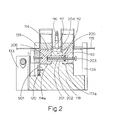
- Figure 2 shows a cross section taken along the line A-A in Figure 1, viewed in the direction indicated by the arrows.
- Figure 3 shows a cross section taken along the line B-B in Figure 1, viewed in the direction indicated by the arrows.
- Figure 4 shows a perspective view of part of the cleaving tool shown in Figure 1.
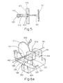
- Figure 5 shows a cross section of a pin for use in the cleaving tool of Figure 1.
- Figures 6a to 6c show schematically the same perspective view of part of the cleaving tool, in order to illustrate the tool at three different stages during a cleaving operation.
- Referring to Figures 1 and 2, the
cleaving tool 111 comprises ananvil 204, fibre clamps 113,114 for clamping anoptical fibre 115 such that it extends across the anvil, in contact with it, and acleaver blade 116 which is mounted on awheel 117. - A
single support block 118 provides mounting for both theanvil 204 and for each of a pair ofoptical fibre clamps support block 118, which is mounted on abase plate 132, has acentral portion 112 flanked on each side by twodownward steps - Referring to Figure 2, the
anvil 204 is designed, as in other known forms of cleaving tool, to provide a support for anoptical fibre 115 when the latter is struck. It comprises a block of material mounted on thecentral portion 112 of thesupport block 118. To each side of theanvil 204 lies one of thefibre clamps anvil 204 is mounted such that, when anoptical fibre 115 is mounted in position ready to be cleaved, the upper surface of theanvil 204 is horizontal and tangential to the bottom of the fibre 15. Theanvil 204 is mounted on thesupport block 118 by adjustable mounting means (not shown) so that, if necessary, the height of the anvil can be adjusted. - The clamps 113,114 shown are of a type known for use in clamping optical fibres and are not therefore described in detail. Briefly, each clamp operates by clamping the fibre, with a resilient pad, into a straight groove in a clamping face.
- Referring again to Figure 1, the clamps 113,114 are mounted to each side of the
central portion 112, on the first downward steps 121,122. One of theclamps 113 is mounted so as to be immobile with respect to thesupport block 118. The other of theclamps 114 however is mounted by means of aleaf spring 120. Theleaf spring 120 extends adjacent to both the side of theclamp 114 and the side of thestep 122, and is attached by means ofscrews screws leaf spring 120. The upper part of thespring 120 is sandwiched between a pressure block 127 (further described below) and thefibre clamp 114 while the lower part of thespring 120 is sandwiched between aclamping plate 901 and thestep 122. This arrangement avoids theleaf spring 120 being bent, in use, about an axis weakened by screw holes and so improves the reliability of the apparatus. - It is important that the clamping faces of the clamps 113,114 are co-planar when the apparatus is set prior to cleaving a fibre 115 (as in Figures 1 and 6a). This is achieved by machining the two
steps clamps clamp respective step nib nibs first clamp 113 is attached to thesupport block 118 and before the leaf spring 120 (which determines the position of the second clamp 114) is attached to thesecond clamp 114 and thesupport block 118. Similar precautions must be taken to ensure that the grooves of the twoclamps - In the arrangement shown, with an
optical fibre 115 clamped over theanvil 204 by the twofibre clamps clamps fibre 115 itself and theleaf spring 120 extends vertically. However, theleaf spring 120 at rest is in the form of a curved resilient plate. Thespring 120 is mounted such that if its upper end were released it would move in a direction away from thefixed clamp 113. Hence, in the arrangement of Figure 1, theleaf spring 120 exerts a force on the associatedfibre clamp 114 in a direction away from thefixed clamp 113. This force is supplemented by an adjustable force provided by an internal spring. - Referring to Figure 2, the
internal spring 201 is mounted in acavity 202 formed by a bore through thecentral portion 112 of thesupport block 118 which is extended by a recess in the inner side of eachclamp clamp 114 is of fixed length and is terminated by a bearingface 206 against which one end of thespring 201 bears. The recess in thefixed clamp 113 however is of adjustable length, being terminated by amovable bearing plate 205. The position of thebearing plate 205 can be adjusted to produce a preselected degree of compression in the spring 201 -and hence a preselected supplementary force acting to separate the twofibre clamps - A
screw 203 serves to adjust the position of thebearing plate 205. Thescrew 203 extends through a threaded bore in thefixed clamp 113 so that its shaft abuts thebearing plate 205 on the side away from thespring 201 and its head is exposed to allow adjustments to be made. - The optimal value of the total force available to act on the fibre varies with the particular type of fibre to be cleaved. It is extremely important, in achieving cleaved fibre ends of high quality, that the value selected is a correct one. Suitable value ranges are known to those skilled in the art and are not therefore detailed here.
- It is important that debris does not interfere with the position of the spring mounted
clamp 114 by finding its way between theclamp 114 and thecentral portion 112 of thesupport block 118. To avoid such interference, the face of theclamp 114 adjacent thecentral portion 112 is recessed, only its upper and side margins remaining (not shown). This allows the position of theclamp 114 to be determined accurately when it lies against thecentral portion 112 while debris will be able to fall harmlessly into the recess. The use of thenibs clamps - Referring again to Figure 1, adjacent to the upper part of the
leaf spring 120 and acting, with the resiliently mountedclamp 114, to sandwich that part of theleaf spring 120, is apressure block 127. Thepressure block 127 is a block of rigid material with acentral projection 128 on its outer vertical face. The surface of theprojection 128 which lies furthest from theclamp 114 extends short of the plane of the outermostvertical face 129 of thesupport block 118. On either side of thecentral projection 128 lie screws 126, mentioned above in connection with theleaf spring 120. Thesescrews 126 pass through thepressure block 127 and theleaf spring 120 to be held by threaded recesses in theclamp 114, thereby holding these three components rigidly together. - Mounted on the outermost
vertical face 129 of thesupport block 118, parallel to thecentral projection 128, is aresilient contact plate 130. Thecontact plate 130 is in the form of a leaf spring which is fixed at its lower end by means of ascrews 131 to theoutermost face 129 of thesupport block 118. Theplate 130 extends vertically upwards in its relaxed state, as far as the upper part of thecentral projection 128. With theplate 130 unstressed, there is therefore a gap between it and thecentral projection 128. - In the region of the
contact plate 130 there is provided ahorizontal control shaft 135. Theshaft 135 is rotatably mounted in asupport 133 and has aturning handle 137 at one end. Adjacent to thecontact plate 130 there is provided acam 136 on thecontrol shaft 135. Thecontrol shaft 135 is positioned such that thecam 136, when turned towards the contact plate 130 (i.e. when theshaft 135 is turned anticlockwise through 90° from the position shown in Figure 1), impinges on the outer surface of thecontact plate 130 and bends it in the direction of the clamps 113,114. This action is further described below. - The
wheel 117 andcleaver blade 116 are arranged as follows. Extending in a direction parallel to that of theoptical fibre 115 is anaxle 138. Thewheel 117, which comprises a disc of material, is fixedly mounted on theaxle 138, each end of which is supported by anaxle support block 139 wich is mounted on thebase plate 132. - Referring to Figure 3,
bearings bearings 801 comprises adiaphragm 803 having an integralannular stem 804. Thediaphragm 803 is seated by means of ashoulder 805 in an aperture in thesupport block 139. The end of theaxle 138 rests in ablind hole 806 in the diaphragm. At the other end of theaxle 138 there is provided a solid plug with a centralblind hole 808 which takes the remaining end of theaxle 138. Both ends of theaxle 138 are conically tapered and each is supported at a short distance from its tip by the margin of its respectiveblind hole bearings - To assemble the
axle 138 in itsbearings diaphragm bearing 801, in position. The second, plug bearing 802 is then slid into position through abore 807 in itsrespective support block 139 and fixed-in place by means of a screw (not shown). Thesecond bearing 802 is positioned so as to impose a preload _on thediaphragm 803. - This arrangement has the advantage that it compensates for differences in thermal expansion or contraction between the
base plate 132 and theaxle 138 which could otherwise affect the action of thecleaver blade 116, particularly where the apparatus is used in extremes of temperature. Further, the preload in thediaphragm 803 acts to compensate for wear in the bearings, 801, 802. - Referring to Figure 4, the
wheel 117 comprises a circular disc. Extending radially from its circumference is anarm 303 which carries thecleaver blade 116. The arrangement is such that rotation of thewheel 117 would cause thecleaver blade 116 to strike an optical fibre in position on the anvil when theblade 116 extends substantially horizontally. - A hair spring 304 (shown schematically), mounted on the
axle 138, acts to rotate thewheel 117. When thecleaver blade 116 is raised, as shown in Figure 4, thespring 304 is tensioned with respect to its rest position and therefore exerts a turning force on thewheel 117, in the direction shown by the arrow X. - The magnitude of the force exerted can be adjusted by altering the position at which an
end 309 of thespring 304 is clamped. That is, theend 309 can be pulled further through, or further out of, the relevant clamping means, so tightening or loosening the turns of thespring 304 on theaxle 138. - An
adjustable damper 307 is provided which acts via aprojection 308 on thewheel 117 to damp its rotation during use of the cleaving tool. Thedamper 307 controls the rotational speed, and therefore the kinetic energy, of the cleaver as theblade 116 strikes the fibre (not shown). This, as is already known in the art, affects the quality of the cleaved fibre end produced. - Referring to Figures 1 and 5, the
control shaft 135 extends beyond itssupport 133 on the side away from thecontact plate 130. The extended portion of thecontrol shaft 135 is provided with simple cam profile by means of a flat 140 which is directed when the apparatus is set, as shown, away from thewheel 117. A spring mountedpin 142 co-operates with said cam profile, and with aprojection 141 on the face of thewheel 117, to control rotation of thewheel 117 in the direction of the turning force exerted by thehair spring 304, in a manner further detailed below. - Referring to Figure 4, extending horizontally and parallel to the face of the
wheel 117 which carries theprojection 141 there is mounted astop 311. Thestop 311 has acylindrical portion 312 with a threaded external surface and a conically taperedpoint 313. Thestop 311 is screwed by means of its threaded portion into a threaded bore in asupport 314. Thetapered point 313 is directed towards the fibre clamps (not shown) and lies closer to thewheel 117 than does the end of theprojection 141. - The
wheel 117, and all the parts to which it is fixedly attached, is balanced about the axis of thewheel bearing axle 138. Compensation for the lack of rotational symmetry of thewheel 117 and the attached parts is provided byholes wheel 117. - A second aspect of the compensating holes 400,401,402 is that they can be used to determine the mass and therefore the inertia of the
wheel 117 and the parts to which it is fixedly attached. This inertia is an important factor in the cleaving characteristics of the cleaving tool, as is known to those skilled in the art, and will be selected as required. - The cleaving apparatus is used to cleave an
optical fibre 115 as described below, with reference to Figures 6a to 6c. - The portion of the
optical fibre 115 which is to be cleaved is prepared, for instance by removal of any protective layers it is necessary to remove. The preparation requirements for use of the cleaving apparatus described are not particular to the apparatus and will be clear to a person skilled in the art of cleaving optical fibres. - The
wheel 117 is positioned with thearm 303 in a raised position, as shown in Figure 6a, and thecontrol shaft 135 is subsequently positioned so that thecam 136 projects horizontally, in the direction of the fibre clamps 113, 114. Thewheel 117 is then maintained with thearm 303 raised by means of theprojection 141 and the spring mountedpin 142. Further, thecontact plate 130 is held against thecentral projection 128 of the pressure block 127 by thecam 136. Thecontact plate 130 acts via thecentral projection 128 to hold the resiliently mountedfibre clamp 114 in an upright position, equivalent to that of the fixedclamp 113, against the forces exerted by theleaf spring 120 and the internal spring 201 (Figure 2). - The
optical fibre 115 is placed in the fibre clamps 113, 114 so that the prepared portion of theoptical fibre 115 lies across theanvil 204. It is important, as is known in the art, that thefibre 115 should not be placed under torsional strain in the clamps 113,114. This can be aided by closing the clamp adjacent a short end of thefibre 115 only after closing the other clamp. In this way, any torsional strain is released by rotation of the short end. - Referring to Figure 6b, to set the apparatus prior to cleaving, the
control shaft 135 is turned through 90° to bring thecam 136 to a position directed vertically downwards. Thewheel 117 remains held in the same position by means of thepin 142. Both fibre clamps 113, 114 also remain in the same positions as before but thecam 136 no longer acts via thecontact plate 130 and pressure block 127 to oppose the forces exerted by theleaf spring 120 and internal spring 201 (Figure 2). Instead thecontact plate 130 comes away from thepressure block 127 and theoptical fibre 115 itself, being clamped at fixed positions by the two fibre clamps 113, 114, prevents the resiliently mountedclamp 114. from , moving away from the fixedclamp 113. - The
optical fibre 115 is therefore brought under a longitudinal tension determined by the forces exerted by theleaf spring 120 and the internal spring 201 (Figure 2). - Referring to Figure 6c, to cleave the
fibre 115, thecontrol shaft 135 is then turned through a further 90°. This turns the flat 140 on the extended portion of thecontrol shaft 135 towards the spring mountedpin 142 which as a result can be displaced by its associated spring (not shown) away from thewheel 117, sufficiently to clear theprojection 141 on thewheel 117. Thewheel 117 is thus freed to rotate until thecleaver blade 116 strikes theoptical fibre 115 on theanvil 204, thereby cleaving it. - The resiliently mounted
clamp 114 will tilt away from the fixedly mountedclamp 113, under the combined actions of theleaf spring 120 and the internal spring 201 (Figure 2) in the absence of the restraint hitherto provided by the intactoptical fibre 115, into the position shown in Figure 6c. - The
cleaver blade 116 will penetrate into theoptical fibre 115 to a distance related to the extent of rotation of thewheel 117 when theprojection 141 contacts thestop 311. Rotation of thestop 311 in itssupport 314 results in horizontal displacement of the taperedpoint 313 across the face of thewheel 117. The diameter of the taperedpoint 313 where it is contacted by theprojection 141 on rotation of thewheel 117 is varied as a result and consequently the maximum extent of rotation of thewheel 117, and penetration of theblade 116 into thefibre 115, are also varied. - It is known in the art that the extent to which the
blade 116 can penetrate afibre 115 has a major effect on the quality of cleaved fibre end produced. It is also known that the extent will vary between fibre types. Good quality fibre ends have been produced in monomode fibres ofdiameter 125 pm where thestop 311 was set such as to allow theblade 116 to reach a position 5 um below the upper surface of thefibre 115. However it will be understood that the position of the stop will be peculiar to each fibre type and must be set accordingly. - Regarding the tensile load applied to the
fibre 115 before cleaving, although in practice the tension is applied by a member which travels along a curve when released (generated by the tilting movement of the resiliently mounted clamp 114), it will be clear that the tension which is applied to thefibre 115 before cleaving is axial. Although thefibre 115 takes a finite time to cleave completely, and during that finite time theclamp 114 will start to tilt, the deviation from an axial load which is introduced should be insignificant. The shallower the curve introduced by the tilting movement of the resiliently mountedclamp 114, the closer will be the approximation to an axially applied tension throughout the cleaving action. Although it is considered that the distance between the fibre and thescrews 125 which mount theleaf spring 120 on thesupport block 118 could be considerably reduced, the distance in the embodiment described above is about 2.5 cm. - The arrangement described offers a number of advantageous features in the cleaving of optical fibres. In particular, the movement of the
cleaver blade 116 is independent of gravity and will not be affected by gravitational forces due to changes in orientation of the aparatus. There is no necessity therefore to mount the apparatus on a horizontal surface or to allow for changing gravitational forces which might occur for instance on board a ship. It should be noted, particularly in this respect, that although the cleaving tool described above, and shown in the Figures, is oriented such that the optical fibre is struck from above, this is not a necessary orientation of a cleaving tool according to the invention. - It will be clear that many alternative arrangements would produce the same advantageous feature, including replacement of the wheel by a rod carrying a cleaver blade at one end. Further, whatever means is used to balance the cleaver, that is the cleaver blade and everything that rotates with it in use, may be applied to any part of the cleaver. Therefore the
holes rotatable axle 138, or by suitable weights mounted on thewheel 117 oraxle 138. - It should be noted that the
wheel 117 is fixedly mounted on anaxle 138 whose length is comparable with the distance between thecleaver blade 116 and the axis of rotation of the cleaver. In the present embodiment theaxle 138 is about 2.5 cm long and the distance between theblade 116 and the axis of rotation is about 3.5 cm. The cleaver, in this case comprising thewheel 117 andaxle 138 together, is therefore supported at two points which are spaced relatively far apart, that is, at the ends of theaxle 138. This is advantageous in that should displacement occur at the associated bearings, for instance due to wear in spite of thepreloaded diaphragm 803, then any resulting displacement of thecleaver blade 116 due to tilting of thewheel 117 will tend to be small. In comparison, were thewheel 117 for example to be rotatably supported on theaxle 138 then the same amount of wear in the associated bearings would cause thewheel 117 to tilt relative to theaxle 138 to a much greater degree, generating much greater displacement of thecleaver blade 116. - By designing the
control shaft 135 so that its rotation acts first to apply tension to thefibre 115 and then to release thewheel 117, causing cleaving of thefibre 115, the arrangement described is particularly simple to operate. The arrangement may also be modified so that in moving the control shaft back to its starting point, with thecam 136 holding thecontact plate 130 against thepressure block 127, thewheel 117 is similarly moved back to its starting point witharm 303 raised, without any further action being taken. - It will be clear that other features of the cleaving apparatus described above are not essential. For instance the
internal spring 201 could be left out and the force exerted by the resilient mounting of the resiliently mountedfibre clamp 114 designed to be adjustable.
Claims (12)
Priority Applications (1)
| Application Number | Priority Date | Filing Date | Title |
|---|---|---|---|
| AT85300854T ATE33127T1 (en) | 1984-02-09 | 1985-02-08 | CUTTING DEVICE. |
Applications Claiming Priority (2)
| Application Number | Priority Date | Filing Date | Title |
|---|---|---|---|
| GB8403440 | 1984-02-09 | ||
| GB848403440A GB8403440D0 (en) | 1984-02-09 | 1984-02-09 | Cleaving apparatus |
Publications (2)
| Publication Number | Publication Date |
|---|---|
| EP0152289A1 EP0152289A1 (en) | 1985-08-21 |
| EP0152289B1 true EP0152289B1 (en) | 1988-03-23 |
Family
ID=10556341
Family Applications (1)
| Application Number | Title | Priority Date | Filing Date |
|---|---|---|---|
| EP85300854A Expired EP0152289B1 (en) | 1984-02-09 | 1985-02-08 | Cleaving apparatus |
Country Status (11)
| Country | Link |
|---|---|
| US (1) | US4667862A (en) |
| EP (1) | EP0152289B1 (en) |
| JP (1) | JPS61501173A (en) |
| AT (1) | ATE33127T1 (en) |
| AU (1) | AU3938785A (en) |
| CA (1) | CA1234537A (en) |
| DE (1) | DE3561942D1 (en) |
| DK (1) | DK461785A (en) |
| FI (1) | FI853903A7 (en) |
| GB (1) | GB8403440D0 (en) |
| WO (1) | WO1985003502A1 (en) |
Families Citing this family (16)
| Publication number | Priority date | Publication date | Assignee | Title |
|---|---|---|---|---|
| IT1188342B (en) * | 1986-02-06 | 1988-01-07 | Pirelli Cavi Spa | METHOD AND EQUIPMENT FOR CUTTING OPTICAL FIBERS |
| US5501385A (en) * | 1994-12-08 | 1996-03-26 | The United States Of America As Represented By The United States Department Of Energy | Large core fiber optic cleaver |
| JP3325181B2 (en) * | 1996-05-23 | 2002-09-17 | 河村電線工業株式会社 | Optical fiber cutting method and cutting device |
| BE1014859A3 (en) * | 2002-05-31 | 2004-05-04 | Picanol Nv | Device and method for cutting a thread. |
| AU2003261613A1 (en) * | 2002-08-26 | 2004-09-17 | Ilsin Precision Co., Ltd. | Automatic optical-fiber cutter |
| US7669744B2 (en) * | 2003-08-04 | 2010-03-02 | 3M Innovative Properties Company | Device and method for cleaving optical fibers |
| US20050109177A1 (en) * | 2003-08-22 | 2005-05-26 | Wiley Robert G. | Rotary large diameter fiber cleaver |
| US7092284B2 (en) * | 2004-08-20 | 2006-08-15 | Infineon Technologies Ag | MRAM with magnetic via for storage of information and field sensor |
| WO2009051918A1 (en) * | 2007-10-19 | 2009-04-23 | 3M Innovative Properties Company | Bladeless optical fiber cleaver and method |
| ES2902278T3 (en) * | 2009-04-17 | 2022-03-25 | Corning Res & Dev Corp | Bladeless Fiber Optic Cleaver |
| JP5639455B2 (en) * | 2010-12-13 | 2014-12-10 | 株式会社フジクラ | Optical fiber cutting device and optical fiber cutting method |
| KR101826654B1 (en) * | 2012-02-20 | 2018-02-07 | 이노 인스트루먼트 (차이나). 인코퍼레이션 | Fiber cleaver |
| US10605990B2 (en) * | 2014-09-17 | 2020-03-31 | Cudoquanta Florida, Inc. | Tensioning device having a flexure mechanism for applying axial tension to cleave an optical fiber and method |
| JP6340401B2 (en) * | 2016-11-22 | 2018-06-06 | 株式会社フジクラ | Optical fiber cutter |
| US10656335B2 (en) | 2018-07-18 | 2020-05-19 | International Business Machines Corporation | Cleaving fibers of differing composition |
| CN110605744B (en) * | 2019-10-20 | 2021-07-06 | 赵海荣 | Production line control method |
Family Cites Families (6)
| Publication number | Priority date | Publication date | Assignee | Title |
|---|---|---|---|---|
| US745965A (en) * | 1902-12-01 | 1903-12-01 | Brocton Supply Company | Welt-slitting machine. |
| US2048360A (en) * | 1934-03-02 | 1936-07-21 | Spanel Abram Nathaniel | Method and apparatus for making helically wound tubes |
| US4557049A (en) * | 1982-04-15 | 1985-12-10 | Gte Products Corporation | Hand held fiber optic cleaving tool |
| US4473942A (en) * | 1982-04-21 | 1984-10-02 | At&T Bell Laboratories | Precision cleaving of optical fibers |
| GB2134101B (en) * | 1983-01-05 | 1986-08-13 | Gen Electric Co Plc | Method of and apparatus for cleaving optical fibres |
| JP3365467B2 (en) * | 1996-06-17 | 2003-01-14 | 理化工業株式会社 | Stick type surface temperature measuring device |
-
1984
- 1984-02-09 GB GB848403440A patent/GB8403440D0/en active Pending
-
1985
- 1985-02-08 AT AT85300854T patent/ATE33127T1/en not_active IP Right Cessation
- 1985-02-08 WO PCT/GB1985/000053 patent/WO1985003502A1/en not_active Ceased
- 1985-02-08 CA CA000473964A patent/CA1234537A/en not_active Expired
- 1985-02-08 EP EP85300854A patent/EP0152289B1/en not_active Expired
- 1985-02-08 AU AU39387/85A patent/AU3938785A/en not_active Abandoned
- 1985-02-08 US US06/791,141 patent/US4667862A/en not_active Expired - Fee Related
- 1985-02-08 DE DE8585300854T patent/DE3561942D1/en not_active Expired
- 1985-02-08 JP JP60500832A patent/JPS61501173A/en active Pending
- 1985-02-08 FI FI853903A patent/FI853903A7/en not_active Application Discontinuation
- 1985-10-09 DK DK461785A patent/DK461785A/en not_active Application Discontinuation
Also Published As
| Publication number | Publication date |
|---|---|
| AU3938785A (en) | 1985-08-27 |
| FI853903A0 (en) | 1985-10-08 |
| ATE33127T1 (en) | 1988-04-15 |
| CA1234537A (en) | 1988-03-29 |
| GB8403440D0 (en) | 1984-03-14 |
| FI853903L (en) | 1985-10-08 |
| DK461785D0 (en) | 1985-10-09 |
| WO1985003502A1 (en) | 1985-08-15 |
| US4667862A (en) | 1987-05-26 |
| EP0152289A1 (en) | 1985-08-21 |
| DE3561942D1 (en) | 1988-04-28 |
| JPS61501173A (en) | 1986-06-12 |
| DK461785A (en) | 1985-10-09 |
| FI853903A7 (en) | 1985-10-08 |
Similar Documents
| Publication | Publication Date | Title |
|---|---|---|
| US4667862A (en) | Cleaving apparatus and method | |
| US6578747B2 (en) | Tool for angled cleaving of optical fibers or the like | |
| US4216004A (en) | Method of breaking optical fibers | |
| EP0097702B1 (en) | Method and apparatus for scribing and cleaving optical fibers | |
| US9933571B2 (en) | Profiling of cleaved angled end faces of optical fiber(s) | |
| GB2287552A (en) | Curved-angle cleaving of optical fibers | |
| US5188268A (en) | Device for cutting an optical fiber obliquely | |
| CA1208119A (en) | Cleaving device for optical fibers | |
| US5123581A (en) | Oblique fracturing of optical fibers by offset shearing | |
| US4548630A (en) | Fibre fusion splicing | |
| GB1570032A (en) | Thermal fusion splicers for optical fibres | |
| EP0267744B1 (en) | Cleaving apparatus | |
| EP0105909A1 (en) | PRECISION COLUMNS OF OPTICAL FIBERS. | |
| JPH068123A (en) | Grinding device | |
| EP1230531B1 (en) | Fibre-optical strain-gauge and method of its manufacture | |
| US5397185A (en) | Device for the axial support of a rotatable body, and positioning device provided with such a device | |
| CN217112798U (en) | High-precision cutter capable of adjusting angle of end face of optical fiber | |
| JPH04230823A (en) | Method and apparatus for aligning optical fiber | |
| JPH0625803B2 (en) | Optical fiber cutting stress generator | |
| CN113126208A (en) | Optical fiber cutter slider using elastic blade support | |
| US4591082A (en) | Optical fiber severing device and method | |
| JPS599201Y2 (en) | Optical fiber cutting device | |
| JP2004233417A (en) | Optical fiber cutter and optical fiber cutting method | |
| JPH0833499B2 (en) | Optical fiber axis alignment device | |
| JPH0289009A (en) | Optical fiber clamping mechanism |
Legal Events
| Date | Code | Title | Description |
|---|---|---|---|
| PUAI | Public reference made under article 153(3) epc to a published international application that has entered the european phase |
Free format text: ORIGINAL CODE: 0009012 |
|
| AK | Designated contracting states |
Designated state(s): AT BE CH DE FR GB IT LI LU NL SE |
|
| 17P | Request for examination filed |
Effective date: 19851011 |
|
| 17Q | First examination report despatched |
Effective date: 19860808 |
|
| GRAA | (expected) grant |
Free format text: ORIGINAL CODE: 0009210 |
|
| RAP1 | Party data changed (applicant data changed or rights of an application transferred) |
Owner name: BRITISH TELECOMMUNICATIONS PUBLIC LIMITED COMPANY |
|
| AK | Designated contracting states |
Kind code of ref document: B1 Designated state(s): AT BE CH DE FR GB IT LI LU NL SE |
|
| PG25 | Lapsed in a contracting state [announced via postgrant information from national office to epo] |
Ref country code: NL Effective date: 19880323 Ref country code: LI Effective date: 19880323 Ref country code: IT Free format text: LAPSE BECAUSE OF FAILURE TO SUBMIT A TRANSLATION OF THE DESCRIPTION OR TO PAY THE FEE WITHIN THE PRESCRIBED TIME-LIMIT;WARNING: LAPSES OF ITALIAN PATENTS WITH EFFECTIVE DATE BEFORE 2007 MAY HAVE OCCURRED AT ANY TIME BEFORE 2007. THE CORRECT EFFECTIVE DATE MAY BE DIFFERENT FROM THE ONE RECORDED. Effective date: 19880323 Ref country code: FR Free format text: THE PATENT HAS BEEN ANNULLED BY A DECISION OF A NATIONAL AUTHORITY Effective date: 19880323 Ref country code: CH Effective date: 19880323 Ref country code: BE Effective date: 19880323 Ref country code: AT Effective date: 19880323 |
|
| REF | Corresponds to: |
Ref document number: 33127 Country of ref document: AT Date of ref document: 19880415 Kind code of ref document: T |
|
| PG25 | Lapsed in a contracting state [announced via postgrant information from national office to epo] |
Ref country code: SE Effective date: 19880331 |
|
| REF | Corresponds to: |
Ref document number: 3561942 Country of ref document: DE Date of ref document: 19880428 |
|
| REG | Reference to a national code |
Ref country code: CH Ref legal event code: PL |
|
| NLV1 | Nl: lapsed or annulled due to failure to fulfill the requirements of art. 29p and 29m of the patents act | ||
| EN | Fr: translation not filed | ||
| PLBE | No opposition filed within time limit |
Free format text: ORIGINAL CODE: 0009261 |
|
| STAA | Information on the status of an ep patent application or granted ep patent |
Free format text: STATUS: NO OPPOSITION FILED WITHIN TIME LIMIT |
|
| PG25 | Lapsed in a contracting state [announced via postgrant information from national office to epo] |
Ref country code: LU Free format text: LAPSE BECAUSE OF NON-PAYMENT OF DUE FEES Effective date: 19890228 |
|
| 26N | No opposition filed | ||
| PG25 | Lapsed in a contracting state [announced via postgrant information from national office to epo] |
Ref country code: DE Effective date: 19891101 |
|
| PGFP | Annual fee paid to national office [announced via postgrant information from national office to epo] |
Ref country code: GB Payment date: 19891231 Year of fee payment: 6 |
|
| PG25 | Lapsed in a contracting state [announced via postgrant information from national office to epo] |
Ref country code: GB Effective date: 19910208 |
|
| GBPC | Gb: european patent ceased through non-payment of renewal fee |