EP0151868B1 - Pressure monitoring of closed containers - Google Patents
Pressure monitoring of closed containers Download PDFInfo
- Publication number
- EP0151868B1 EP0151868B1 EP84307859A EP84307859A EP0151868B1 EP 0151868 B1 EP0151868 B1 EP 0151868B1 EP 84307859 A EP84307859 A EP 84307859A EP 84307859 A EP84307859 A EP 84307859A EP 0151868 B1 EP0151868 B1 EP 0151868B1
- Authority
- EP
- European Patent Office
- Prior art keywords
- stud
- closure member
- container
- movable member
- capsule
- Prior art date
- Legal status (The legal status is an assumption and is not a legal conclusion. Google has not performed a legal analysis and makes no representation as to the accuracy of the status listed.)
- Expired
Links
Images

Classifications
-
- G—PHYSICS
- G01—MEASURING; TESTING
- G01M—TESTING STATIC OR DYNAMIC BALANCE OF MACHINES OR STRUCTURES; TESTING OF STRUCTURES OR APPARATUS, NOT OTHERWISE PROVIDED FOR
- G01M3/00—Investigating fluid-tightness of structures
- G01M3/02—Investigating fluid-tightness of structures by using fluid or vacuum
- G01M3/26—Investigating fluid-tightness of structures by using fluid or vacuum by measuring rate of loss or gain of fluid, e.g. by pressure-responsive devices, by flow detectors
- G01M3/32—Investigating fluid-tightness of structures by using fluid or vacuum by measuring rate of loss or gain of fluid, e.g. by pressure-responsive devices, by flow detectors for containers, e.g. radiators
- G01M3/3236—Investigating fluid-tightness of structures by using fluid or vacuum by measuring rate of loss or gain of fluid, e.g. by pressure-responsive devices, by flow detectors for containers, e.g. radiators by monitoring the interior space of the containers
- G01M3/3272—Investigating fluid-tightness of structures by using fluid or vacuum by measuring rate of loss or gain of fluid, e.g. by pressure-responsive devices, by flow detectors for containers, e.g. radiators by monitoring the interior space of the containers for verifying the internal pressure of closed containers
-
- G—PHYSICS
- G01—MEASURING; TESTING
- G01L—MEASURING FORCE, STRESS, TORQUE, WORK, MECHANICAL POWER, MECHANICAL EFFICIENCY, OR FLUID PRESSURE
- G01L9/00—Measuring steady of quasi-steady pressure of fluid or fluent solid material by electric or magnetic pressure-sensitive elements; Transmitting or indicating the displacement of mechanical pressure-sensitive elements, used to measure the steady or quasi-steady pressure of a fluid or fluent solid material, by electric or magnetic means
- G01L9/0033—Transmitting or indicating the displacement of bellows by electric, electromechanical, magnetic, or electromagnetic means
Definitions
- This invention relates to apparatus for monitoring the pressure within a sealed container from outside the container.
- US-A-3140 612 discloses an ultrasonic pressure sensor device. However, there is no disclosure of how the device could be made to work through the wall of a sealed container, while still preserving the integrity of the sealing of the container.
- apparatus for monitoring the pressure . within a sealed container comprising:
- the containers will be cylindrical containers, typically about 470 cm long by 35 cm in diameter.
- the proposal envisages that large numbers of the containers will be stored in a storage vault, in a concrete storage matrix having a large number of vertically disposed cylindrical channels, each capable of receiving at least one container.
- the vault will be provided with remote handling equipment, horizontally movable in two orthogonal directions, for lowering the containers into the channels, and for lifting them out again should that prove necessary.
- the spent nuclear fuel elements have been placed in such a container, it is proposed to fill the container with argon at 2 atmospheres pressure, and to weld the container shut to seal it.
- the argon will be introduced into the container via a filler neck at the top of the container, which filler neck will contain a combined valve and closure plug.
- This closure plug will be movable axially . into the filler neck after the introduction of the argon, from an open position to a closed position, and then welded in the closed position.
- the present invention provides for the incorporation, in this closure plug, of a pressure sensor which will permit the pressure inside the container to be sensed from outside the container, preferably by means of measuring equipment carried by the aforementioned remote handling equipment.
- a pressure sensor which will permit the pressure inside the container to be sensed from outside the container, preferably by means of measuring equipment carried by the aforementioned remote handling equipment.
- a closure plug incorporating such a pressure sensor is shown in Figure 1.
- closure plug of Figure 1 is indicated generally at 10, and is shown welded into the opening in the top of the filler neck 12 of a sealed steel container of the kind described above, in order to close and seal the container.
- the container is filled with argon at about two atmospheres pressure.
- the plug 10 comprises a circular base member 14, constituting the part thereof which is actually welded within the opening of the filter neck 12, and a hollow cylindrical skirt 16 which projects coaxially downwardly from the base member 14 into the interior of the filler neck.
- the plug 10 Prior to welding, the plug 10 is movable axially into and out of the filler neck 12, the skirt 16 being arranged to form with the interior of the filler neck 12 an additional valve which is closed when the plug 10 reaches the position shown in Figure 1: however, this valve does not form part of the present invention, and so is not shown in Figure 1.
- a circular- section metal bellows 18 is coaxial with the base member 14, and is closed at its other end by a welded-on circular steel plate (or disc) 20, also coaxial with the base member.
- the bellows 18 and the plate 20 thus together define a sealed expansible capsule 22 secured to the underside of the base member 14.
- a cylindrical stud 24 Disposed coaxially inside the capsule 22, and projecting from the base member 14, is a cylindrical stud 24, which is preferably formed integrally with the base member.
- the stud 24 projects towards and into close proximity with the plate 20, as will hereinafter become apparent.
- the downwardly facing end face of the stud 24 and the upwardly facing upper face of the plate 20, are precisely parallel to each other (and perpendicular to their common axis).
- a spring 26 which thus urges the plate 20 away from the free end of the stud 24.
- the closure plug 10 having been welded into its sealed and pressurised container, can be used in two principal ways.
- the capsule 22 is evacuated during manufacture of the closure plug 10. Additionally, the respective dimensions of the bellows and the stud 24, and the respective stiffnesses of the bellows 18 and the spring 26, are selected such that while the pressure within the container remains at its proper level (i.e. about two atmospheres), the plate 20 firmly contacts the free end of the stud 24, but if the pressure within the container falls below its proper level by more than a given amount, the spring 26 will lift the plate 20 from the free end of the stud 24.
- This lifting of the plate 20 is detected by ultrasonic pulse echo techniques, using an ultrasonic transmitter/receiver (or probe) placed in good acoustic contact with the exposed upper surface of the base member 14. While the plate 20 is in contact with the free end of the stud 24, then in response to each ultrasonic pulse directed downwardly (as viewed in Figure 1) into the base member 14, a first echo will be received from the interface between the stud and the plate, and a second echo will be received from the lower face of the plate remote from this interface. However, when the plate lifts, this second echo will disappear.
- the capsule 22 is filled with an inert gas, e.g. argon, typically at a relatively low pressure, for example one atmosphere or less, during manufacture of the closure plug.
- an inert gas e.g. argon
- the aforementioned dimensions and stiffnesses are selected such that the plate 20 is just clear of the free end of the stud 24 when the pressure within the container is at its proper value. Then, if the pressure within the container begins to fall, the gap between the plate 20 and the free end of the stud 24 will progressively increase, and this increase can be detected using the aforementioned ultrasonic transmitter/ receiver on the upper surface of the base member 14.
- closure plug shown in Figure 2 is indicated generally at 50, and fits into the container in exactly the same way as the closure plug 10 of Figure 1.
- closure plug 50 has some parts in common with the closure plug 10, and these common parts have therefore been given the same reference numbers as were used in relation to the plug 10 of Figure 1.
- the closure plug 50 includes the circular base member 14 and the hollow cylindrical skirt 16 of the plug 10, but welded to the underside of the base 14, coaxially within the skirt 16, is a short cylindrical stud 52 having a resonantly vibratable disc 54 coaxially secured to its free end. Closely adjacent the disc 54 is a circular plate 56, welded to and closing one end of a circular section metal bellows 58. The other end of the bellows 58 is closed by a welded-on metal disc 60, which is welded in turn to supporting bars 62 extending diametrically or chordally across the skirt 16.
- the bellows 58 and the plates 56, 60 thus define a sealed expansible capsule 64, which is coaxially disposed within the skirt 16. This capsule 64 is evacuated or filled with a low pressure inert gas during manufacture of the plug 50, and contains a spring 66 which urges the plate 56 towards the disc 54.
- the disc 54 is made from a piezoelectric, mag- netostrictive or other suitable material which can be remotely excited to produce resonant vibration of the disc.
- This resonant vibration is excited by a suitable sonic, ultrasonic or electric impulse producing means, which is placed in contact with the exposed upper surface of the base member 14, and which includes vibration sensing means responsive to the resonant vibration thus excited.
- the capsule 64 and the spring 66 are designed such that while the pressure within the container remains at its proper level, the disc 54 and the plate 56 are spaced apart, but when this pressure falls below its proper level by more than a given amount, the plate 56 contacts the disc 54. As long as the disc 54 and the plate 56 are spaced apart, resonant vibration of the disc 54 can be excited as described, but as soon as they come into contact, the damping effect of this contact means that resonant vibration can no longer be excited. It is this presence or absence of resonant vibration which is sensed by the vibration sensing means.
- closure plug of Figure 3 is indicated generally at 70, and again has some parts in common with the closure plug 10 of Figure 1. These common parts have therefore been given the same reference numbers as were used in relation to the closure plug 10.
- the closure plug 70 includes the circular base member 14 and hollow cylindrical skirt 16 of the plug 10, but the skirt 16 is welded to the base member 14, and its lower part 72 is provided with a number of longitudinally extending slots 74.
- the lower (and much greater) part 72 of the skirt 16 is a close sliding fit within the lower portion 12a of the filler neck 12 of the container in which the plug 70 is fitted, the slots 74 being provided to facilitate filling the container with argon as described earlier.
- the upper (and unslotted) part 76 of the skirt 16 is an interference fit in the lower portion 12a of the filler neck 12, to provide the additional valve mentioned in relation to Figure 1.
- the exposed upper surface of the base member 14 is provided with a coaxially disposed cylindrical recess 78, for receiving and locating the aforementioned ultrasonic transmitter/receiver in exact alignment with the stud 24.
- the walls of the stud diverge downwardly as viewed in Figure 3, making an angle of about 4° with the axis of the stud.
- the sealed capsule 22 is partially filled with mercury, as indicated at 80, such that the lower end of the stud 24 is immersed in the mercury.
- the mercury thus provides a good acoustic transmission path from the flat lower end of the stud 24 to the flat upper face of the plate 20 which defines the movable base of the capsule 22.
- this lower end is coated during manufacture with a layer of copper upon which is deposited a layer of silver.
- the thickness of the plate is selected to be one quarter, three quarters (or in the general case n quarters, where n is odd) of the predominant wave length of the ultrasonic pulses being directed downwardly into the base member 14.
- the disc 20 of the closure plug 70 is integrally formed as the base of an inverted cup-shaped member 82.
- the downwardly extending cylindrical wall 84 of the member 82 is provided with two axially-spaced, outwardly extending, cylindrical flanges 86, which are a close sliding fit within the skirt 16. This arrangement constrains the member 82 to move precisely parallel to its own axis and that of the stud 24, so maintaining the faces of the plate 22 precisely parallel to the end face of the stud 24.
- a filler port 89 extends longitudinally through the wall 84, generally parallel to the axis of the member 82, to permit the introduction of the mercury into the capsule 22 during manufac- tu re.
- the axial extent of the bellows can be reduced so that their maximum expected length in use is less than the length of the stud 24, the lower end of the bellows then being welded to a coaxially disposed containment wall which forms an extension of the bellows and which is welded to or integral with the plate 22.
- a separate such containment wall can extend upwardly from the plate 22 into the annular space between the bellows 18 and the stud 24, as shown in dotted lines at 87.
- the mercury can be replaced by another suitable liquid metal, e.g. a mixture of gallium and indium in the approximate ratio of 3:1, optionally containing up to 10% tin.
- a suitable liquid metal e.g. a mixture of gallium and indium in the approximate ratio of 3:1, optionally containing up to 10% tin.
- other suitable acoustically transmissive liquids can be used.
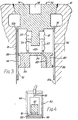
- FIG 4 shows, on a slightly enlarged scale, an ultrasonic probe 90 suitable for use with the closure plug 70.
- the probe 90 comprises a piezoelectrical crystal 91, which is mounted between a cylindrical damping slug 92 and a disc 93 forming the front face of the probe 90.
- the disc 93 is secured in the open end of a,cylindrical housing 94 made from stainless steel, through which electrical leads 95 enabling high voltage pulses to be applied between the front and rear faces of the crystal 91 are led.
- the space within the housing 94 around the crystal 91, the damping slug 92 and the lead 95 is filled with a suitable potting compound.
- An acoustic coupling pad 96 e.g. of polyurethane, is secured to the front face 90, to provide good coupling between this front face and the base member 14 when the probe 90 is located in the recess 78 ( Figure 3).
- the stud 52 and disc 54 can simply be omitted, and the distance between the plate 56 and the underside . of the base member 14 can be sensed ultrasonically as described in relation to Figure 1.
- the surfaces from which the pulses are to be reflected can be shaped to preferentially reflect the pulses back in as close to the same direction from which they come as possible.
- a resonantly vibratable wire can be connected either between the free end of the stud 24 and the plate 20 of Figure 1, or between the end of the stud 52 and the plate 56 of Figure 2 (with the disc 54 simply being omitted).
- changes in the pressure within the container will cause the respective capsule 22 or 64 to change the tension in, and thus the resonant frequency of, the wire, which change can be sensed by the aforementioned vibration sensing means.
- the base member 14 of Figure 1 has an insulated electrode (e.g. of the kind presently offered for sale by the Applicants in connection with their Hydrastep boiler water level sensing apparatus) passing coaxially therethrough, in place of the stud 24 of Figure 1 or the stud 52 and disc 54 of Figure 2.
- a plate forming one plate of a capacitor is secured in electrical contact with the end of this electrode, just beneath the base member 14, the other plate of the electrode being constituted by the plate 20 of Figure 1 or the plate 56 of Figure 2.
- the pressure within the container can then be sensed by sensing the capacitance of this capacitor, as measured between the electrode and the container.
Landscapes
- Physics & Mathematics (AREA)
- General Physics & Mathematics (AREA)
- Electromagnetism (AREA)
- Measuring Fluid Pressure (AREA)
Description
- This invention relates to apparatus for monitoring the pressure within a sealed container from outside the container.
- It has been proposed to store spent nuclear fuel elements in sealed steel containers, which are filled with an inert gas, such as argon, at a pressure of about two atmospheres. Naturally, it is extremely desirable to be able to periodically check that the containers are still sealed, so that if a leak develops, prompt remedial action can be taken before there is any danger of contamination of the environment.
- It is already known e.g. from FR-A-2 183 077, to monitor the pressure within a nuclear fuel element by providing a bellows-type pressure sensor within the element and ultrasonically monitoring, from the outside of the element, the position of a disc which is moved within the element by the bellows. However, the monitoring system of this prior art document fails to provide a reliable transmission path for the ultrasonic pulses between the ultrasonic pulse emission and detection apparatus outside the fuel element and the disc inside the element.
- Additionally, US-A-3140 612 discloses an ultrasonic pressure sensor device. However, there is no disclosure of how the device could be made to work through the wall of a sealed container, while still preserving the integrity of the sealing of the container.
- It is an object of the present invention to provide apparatus for monitoring the pressure within such a sealed container, based upon a pressure sensor which can be incorporated into the container without degrading its integrity, and which can be used in conjunction with sensing means disposed outside the container to monitor the pressure within the container from outside the container.
- According to the present invention, there is provided apparatus for monitoring the pressure . within a sealed container, the apparatus comprising:
- (a) a combined closure means and pressure sensor including:
- a closure member for sealingly closing an opening in the top of the container, said closure member having a first, downwardly-facing, side and a second, upwardly-facing, side, which sides are respectively disposed, in use, inside and outside the container;
- a sealed, expansible, capsule secured to and extending downwardly from the first side of the closure member, said capsule being arranged to expand if the pressure within the container falls; and
- a movable member forming the lower end of the capsule, whereby expansion of the capsule tends to move the movable member away from the first side of the closure member; and
- (b) sensing means which includes means for directing ultrasonic pulses into the closure member from the second side thereof and for receiving echo pulses which have been reflected back through the closure member, whereby to detect changes in the disposition of the movable member with respect to the first side of the closure member and thereby detect changes in the pressure within the container;
characterised in that: - the capsule contains an acoustically transmissive liquid disposed in its lower region and in contact with the movable member, and the closure member is provided with a downwardly extending projection whose lower end is immersed in said liquid and constitutes the first side of the closure member, whereby in response to each ultrasonic pulse directed into the closure member, a first echo pulse is received from the first side of the closure member and a second echo pulse is received via the liquid from the face of the movable member facing the first side of the closure member, the temporal spacing between each first echo pulse and its corresponding second echo pulse being representative of the spacing between the movable member and the first side of the closure member and thus representative of the pressure within the container.
- The invention will now be described, by way of example only, with reference to the accompanying drawings, of which:-
- Figure 1 is a simplified and somewhat diagrammatic sectional view of a container closure plug incorporating one embodiment of a pressure sensor forming part of pressure monitoring apparatus in accordance with the present invention;
- Figure 2 is a simplified and again somewhat diagrammatic sectional view of a container closure plug incorporating another embodiment of a pressure sensor forming part of pressure monitoring apparatus in accordance with the present invention;
- Figure 3 is a simplified and diagrammatic sectional view of a modified version of the closure plug of Figure 1; and
- Figure 4 is a sectional view of an ultrasonic probe for use with the sensor of Figure 3.
- As already mentioned, it has been proposed to store spent nuclear fuel elements in sealed steel containers. The containers will be cylindrical containers, typically about 470 cm long by 35 cm in diameter. The proposal envisages that large numbers of the containers will be stored in a storage vault, in a concrete storage matrix having a large number of vertically disposed cylindrical channels, each capable of receiving at least one container. The vault will be provided with remote handling equipment, horizontally movable in two orthogonal directions, for lowering the containers into the channels, and for lifting them out again should that prove necessary.
- Once the spent nuclear fuel elements have been placed in such a container, it is proposed to fill the container with argon at 2 atmospheres pressure, and to weld the container shut to seal it. The argon will be introduced into the container via a filler neck at the top of the container, which filler neck will contain a combined valve and closure plug. This closure plug will be movable axially . into the filler neck after the introduction of the argon, from an open position to a closed position, and then welded in the closed position.
- The present invention provides for the incorporation, in this closure plug, of a pressure sensor which will permit the pressure inside the container to be sensed from outside the container, preferably by means of measuring equipment carried by the aforementioned remote handling equipment. A closure plug incorporating such a pressure sensor is shown in Figure 1.
- Thus the closure plug of Figure 1 is indicated generally at 10, and is shown welded into the opening in the top of the
filler neck 12 of a sealed steel container of the kind described above, in order to close and seal the container. As already indicated, the container is filled with argon at about two atmospheres pressure. - The
plug 10 comprises acircular base member 14, constituting the part thereof which is actually welded within the opening of thefilter neck 12, and a hollowcylindrical skirt 16 which projects coaxially downwardly from thebase member 14 into the interior of the filler neck. Prior to welding, theplug 10 is movable axially into and out of thefiller neck 12, theskirt 16 being arranged to form with the interior of thefiller neck 12 an additional valve which is closed when theplug 10 reaches the position shown in Figure 1: however, this valve does not form part of the present invention, and so is not shown in Figure 1. - Welded to the underside of the
base member 14, within theskirt 16, is one end of a circular-section metal bellows 18. Thebellows 18 is coaxial with thebase member 14, and is closed at its other end by a welded-on circular steel plate (or disc) 20, also coaxial with the base member. Thebellows 18 and theplate 20 thus together define a sealedexpansible capsule 22 secured to the underside of thebase member 14. - Disposed coaxially inside the
capsule 22, and projecting from thebase member 14, is acylindrical stud 24, which is preferably formed integrally with the base member. Thestud 24 projects towards and into close proximity with theplate 20, as will hereinafter become apparent. The downwardly facing end face of thestud 24 and the upwardly facing upper face of theplate 20, are precisely parallel to each other (and perpendicular to their common axis). - Also disposed coaxially within the
capsule 22, and trapped in compression between theplate 20 and thebase member 14, is aspring 26, which thus urges theplate 20 away from the free end of thestud 24. - The closure plug 10, having been welded into its sealed and pressurised container, can be used in two principal ways.
- In the first way, the
capsule 22 is evacuated during manufacture of theclosure plug 10. Additionally, the respective dimensions of the bellows and thestud 24, and the respective stiffnesses of thebellows 18 and thespring 26, are selected such that while the pressure within the container remains at its proper level (i.e. about two atmospheres), theplate 20 firmly contacts the free end of thestud 24, but if the pressure within the container falls below its proper level by more than a given amount, thespring 26 will lift theplate 20 from the free end of thestud 24. - This lifting of the
plate 20 is detected by ultrasonic pulse echo techniques, using an ultrasonic transmitter/receiver (or probe) placed in good acoustic contact with the exposed upper surface of thebase member 14. While theplate 20 is in contact with the free end of thestud 24, then in response to each ultrasonic pulse directed downwardly (as viewed in Figure 1) into thebase member 14, a first echo will be received from the interface between the stud and the plate, and a second echo will be received from the lower face of the plate remote from this interface. However, when the plate lifts, this second echo will disappear. - In the second, and preferred, way of using the
closure plug 10, thecapsule 22 is filled with an inert gas, e.g. argon, typically at a relatively low pressure, for example one atmosphere or less, during manufacture of the closure plug. In this case, the aforementioned dimensions and stiffnesses are selected such that theplate 20 is just clear of the free end of thestud 24 when the pressure within the container is at its proper value. Then, if the pressure within the container begins to fall, the gap between theplate 20 and the free end of thestud 24 will progressively increase, and this increase can be detected using the aforementioned ultrasonic transmitter/ receiver on the upper surface of thebase member 14. This time, a first echo will be received from the free end of thestud 24, and a second echo will be received from the face of theplate 20 facing thestud 24, i.e. the upper face as viewed in Figure 1. As the pressure within the container falls, the temporal spacing of these echoes will increase, thus enabling a continuous record of changes in the pressure to be kept. - The closure plug shown in Figure 2 is indicated generally at 50, and fits into the container in exactly the same way as the closure plug 10 of Figure 1. To this end, the
closure plug 50 has some parts in common with theclosure plug 10, and these common parts have therefore been given the same reference numbers as were used in relation to theplug 10 of Figure 1. - Thus the
closure plug 50 includes thecircular base member 14 and the hollowcylindrical skirt 16 of theplug 10, but welded to the underside of thebase 14, coaxially within theskirt 16, is a shortcylindrical stud 52 having a resonantlyvibratable disc 54 coaxially secured to its free end. Closely adjacent thedisc 54 is acircular plate 56, welded to and closing one end of a circularsection metal bellows 58. The other end of thebellows 58 is closed by a welded-onmetal disc 60, which is welded in turn to supportingbars 62 extending diametrically or chordally across theskirt 16. Thebellows 58 and theplates expansible capsule 64, which is coaxially disposed within theskirt 16. Thiscapsule 64 is evacuated or filled with a low pressure inert gas during manufacture of theplug 50, and contains aspring 66 which urges theplate 56 towards thedisc 54. - The
disc 54 is made from a piezoelectric, mag- netostrictive or other suitable material which can be remotely excited to produce resonant vibration of the disc. This resonant vibration is excited by a suitable sonic, ultrasonic or electric impulse producing means, which is placed in contact with the exposed upper surface of thebase member 14, and which includes vibration sensing means responsive to the resonant vibration thus excited. - The
capsule 64 and thespring 66 are designed such that while the pressure within the container remains at its proper level, thedisc 54 and theplate 56 are spaced apart, but when this pressure falls below its proper level by more than a given amount, theplate 56 contacts thedisc 54. As long as thedisc 54 and theplate 56 are spaced apart, resonant vibration of thedisc 54 can be excited as described, but as soon as they come into contact, the damping effect of this contact means that resonant vibration can no longer be excited. It is this presence or absence of resonant vibration which is sensed by the vibration sensing means. - The closure plug of Figure 3 is indicated generally at 70, and again has some parts in common with the closure plug 10 of Figure 1. These common parts have therefore been given the same reference numbers as were used in relation to the
closure plug 10. - Thus the closure plug 70 includes the
circular base member 14 and hollowcylindrical skirt 16 of theplug 10, but theskirt 16 is welded to thebase member 14, and itslower part 72 is provided with a number of longitudinally extendingslots 74. The lower (and much greater)part 72 of theskirt 16 is a close sliding fit within the lower portion 12a of thefiller neck 12 of the container in which the plug 70 is fitted, theslots 74 being provided to facilitate filling the container with argon as described earlier. The upper (and unslotted)part 76 of theskirt 16 is an interference fit in the lower portion 12a of thefiller neck 12, to provide the additional valve mentioned in relation to Figure 1. - The exposed upper surface of the
base member 14 is provided with a coaxially disposedcylindrical recess 78, for receiving and locating the aforementioned ultrasonic transmitter/receiver in exact alignment with thestud 24. To further improve the ultrasonic transmission characteristics of the combination of thebase member 14 and thestud 24, the walls of the stud diverge downwardly as viewed in Figure 3, making an angle of about 4° with the axis of the stud. - To further improve the ultrasonic transmission characteristics of the remainder of the closure plug 70, the sealed
capsule 22 is partially filled with mercury, as indicated at 80, such that the lower end of thestud 24 is immersed in the mercury. The mercury thus provides a good acoustic transmission path from the flat lower end of thestud 24 to the flat upper face of theplate 20 which defines the movable base of thecapsule 22. To ensure that the mercury wets the lower end of thestud 24, this lower end is coated during manufacture with a layer of copper upon which is deposited a layer of silver. To eliminate troublesome additional echoes from the lower face of theplate 20, the thickness of the plate is selected to be one quarter, three quarters (or in the general case n quarters, where n is odd) of the predominant wave length of the ultrasonic pulses being directed downwardly into thebase member 14. - It will be noted that the
spring 26 of theclosure plug 10 has been omitted from the closure plug 70, since sufficient resilience is provided by the springiness of the bellows and the compressibility of the gas trapped in the bellows above the mercury. - The
disc 20 of the closure plug 70 is integrally formed as the base of an inverted cup-shapedmember 82. The downwardly extendingcylindrical wall 84 of themember 82 is provided with two axially-spaced, outwardly extending,cylindrical flanges 86, which are a close sliding fit within theskirt 16. This arrangement constrains themember 82 to move precisely parallel to its own axis and that of thestud 24, so maintaining the faces of theplate 22 precisely parallel to the end face of thestud 24. Afiller port 89 extends longitudinally through thewall 84, generally parallel to the axis of themember 82, to permit the introduction of the mercury into thecapsule 22 during manufac- tu re. - To reduce the possibility of loss of mercury in the event that the
bellows 18 is ruptured, the axial extent of the bellows can be reduced so that their maximum expected length in use is less than the length of thestud 24, the lower end of the bellows then being welded to a coaxially disposed containment wall which forms an extension of the bellows and which is welded to or integral with theplate 22. Alternatively, a separate such containment wall can extend upwardly from theplate 22 into the annular space between thebellows 18 and thestud 24, as shown in dotted lines at 87. - Several modifications can be made to the closure plug 70. For example, the mercury can be replaced by another suitable liquid metal, e.g. a mixture of gallium and indium in the approximate ratio of 3:1, optionally containing up to 10% tin. Alternatively, other suitable acoustically transmissive liquids can be used.
- Figure 4 shows, on a slightly enlarged scale, an
ultrasonic probe 90 suitable for use with the closure plug 70. Theprobe 90 comprises apiezoelectrical crystal 91, which is mounted between a cylindrical dampingslug 92 and a disc 93 forming the front face of theprobe 90. The disc 93 is secured in the open end of a,cylindrical housing 94 made from stainless steel, through which electrical leads 95 enabling high voltage pulses to be applied between the front and rear faces of thecrystal 91 are led. The space within thehousing 94 around thecrystal 91, the dampingslug 92 and thelead 95 is filled with a suitable potting compound. Anacoustic coupling pad 96, e.g. of polyurethane, is secured to thefront face 90, to provide good coupling between this front face and thebase member 14 when theprobe 90 is located in the recess 78 (Figure 3). - Many other modifications can be made to the described embodiments of the invention. For example, in the embodiment of Figure 2, the
stud 52 anddisc 54 can simply be omitted, and the distance between theplate 56 and the underside . of thebase member 14 can be sensed ultrasonically as described in relation to Figure 1. Further, in all the embodiments involving the use of ultrasonic pulse echo techniques, the surfaces from which the pulses are to be reflected can be shaped to preferentially reflect the pulses back in as close to the same direction from which they come as possible. - In another modification, a resonantly vibratable wire can be connected either between the free end of the
stud 24 and theplate 20 of Figure 1, or between the end of thestud 52 and theplate 56 of Figure 2 (with thedisc 54 simply being omitted). With this modification, changes in the pressure within the container will cause therespective capsule - In yet another modification, the
base member 14 of Figure 1 has an insulated electrode (e.g. of the kind presently offered for sale by the Applicants in connection with their Hydrastep boiler water level sensing apparatus) passing coaxially therethrough, in place of thestud 24 of Figure 1 or thestud 52 anddisc 54 of Figure 2. A plate forming one plate of a capacitor is secured in electrical contact with the end of this electrode, just beneath thebase member 14, the other plate of the electrode being constituted by theplate 20 of Figure 1 or theplate 56 of Figure 2. The pressure within the container can then be sensed by sensing the capacitance of this capacitor, as measured between the electrode and the container.
Claims (15)
characterised in that:
Applications Claiming Priority (2)
| Application Number | Priority Date | Filing Date | Title |
|---|---|---|---|
| GB8330583 | 1983-11-16 | ||
| GB838330583A GB8330583D0 (en) | 1983-11-16 | 1983-11-16 | Pressure sensors |
Publications (3)
| Publication Number | Publication Date |
|---|---|
| EP0151868A2 EP0151868A2 (en) | 1985-08-21 |
| EP0151868A3 EP0151868A3 (en) | 1986-07-23 |
| EP0151868B1 true EP0151868B1 (en) | 1989-08-16 |
Family
ID=10551856
Family Applications (1)
| Application Number | Title | Priority Date | Filing Date |
|---|---|---|---|
| EP84307859A Expired EP0151868B1 (en) | 1983-11-16 | 1984-11-14 | Pressure monitoring of closed containers |
Country Status (5)
| Country | Link |
|---|---|
| US (1) | US4663965A (en) |
| EP (1) | EP0151868B1 (en) |
| JP (1) | JPS60168030A (en) |
| DE (1) | DE3479441D1 (en) |
| GB (2) | GB8330583D0 (en) |
Families Citing this family (18)
| Publication number | Priority date | Publication date | Assignee | Title |
|---|---|---|---|---|
| HUT45325A (en) * | 1985-07-18 | 1988-06-28 | Kraftwerk Union Ag | Gas tight tank for storaging radiactive materials |
| DE3779920D1 (en) * | 1987-10-28 | 1992-07-23 | Martin Lehmann | METHOD AND ARRANGEMENT FOR DENSITY TESTING A HOLLOW BODY AND USE OF THE METHOD. |
| US6127770A (en) * | 1996-01-20 | 2000-10-03 | Forschungszentrum Karlsrahe Gmbh | Pressure wave sensor |
| RU2210697C2 (en) * | 2001-06-05 | 2003-08-20 | Общество с ограниченной ответственностью НПО "ПОИСК" | High-pressure metal-plastic cylinder, method of and device for checking serviceability of metal-plastic cylinder |
| US7805978B2 (en) | 2006-10-24 | 2010-10-05 | Zevex, Inc. | Method for making and using an air bubble detector |
| WO2009029533A1 (en) * | 2007-08-24 | 2009-03-05 | Zevex, Inc. | Ultrasonic air and fluid detector |
| JP2011505919A (en) * | 2007-12-07 | 2011-03-03 | ゼヴェクス・インコーポレーテッド | Method for inducing lateral motion in Langevin type vibrators using split electrodes of ceramic elements |
| US8539812B2 (en) | 2009-02-06 | 2013-09-24 | Zevek, Inc. | Air bubble detector |
| US8486020B2 (en) | 2010-08-11 | 2013-07-16 | Zevex, Inc. | Pressure sensor and method of use |
| AU2011308700B2 (en) | 2010-10-01 | 2015-04-02 | Zevex, Inc. | Pressure sensor seal and method of use |
| AU2011308757B2 (en) | 2010-10-01 | 2015-03-12 | Zevex, Inc. | Pressure monitoring system for infusion pumps |
| US9048521B2 (en) | 2011-03-24 | 2015-06-02 | Etegent Technologies, Ltd. | Broadband waveguide |
| US9182306B2 (en) | 2011-06-22 | 2015-11-10 | Etegent Technologies, Ltd. | Environmental sensor with tensioned wire exhibiting varying transmission characteristics in response to environmental conditions |
| WO2015066494A2 (en) | 2013-11-01 | 2015-05-07 | Etegent Technologies Ltd. | Broadband waveguide |
| WO2015099884A2 (en) | 2013-11-01 | 2015-07-02 | Etegent Technologies Ltd. | Composite active waveguide temperature sensor for harsh environments |
| US10852277B2 (en) | 2014-04-09 | 2020-12-01 | Etegent Technologies, Ltd. | Active waveguide excitation and compensation |
| US11686627B2 (en) | 2017-04-10 | 2023-06-27 | Etegent Technologies Ltd. | Distributed active mechanical waveguide sensor driven at multiple frequencies and including frequency-dependent reflectors |
| JP6796352B2 (en) * | 2018-10-17 | 2020-12-09 | Q’z株式会社 | Pressure gauge |
Family Cites Families (16)
| Publication number | Priority date | Publication date | Assignee | Title |
|---|---|---|---|---|
| US3140612A (en) * | 1961-09-08 | 1964-07-14 | Electro Sonic Systems Inc | Ultrasonic sensor device |
| US3238774A (en) * | 1963-05-23 | 1966-03-08 | Charles A Gurtler | Pressurized celd micrometeoroid detector |
| GB1100871A (en) * | 1963-12-06 | 1968-01-24 | Atomic Energy Authority Uk | Pressure transducers |
| GB1100723A (en) * | 1964-07-06 | 1968-01-24 | Atomic Energy Authority Uk | Burst nuclear fuel element detection |
| GB1142314A (en) * | 1966-02-24 | 1969-02-05 | Bissett Berman Corp | Vibratory wire pressure transducer |
| GB1276294A (en) * | 1968-05-24 | 1972-06-01 | Secr Defence | Vibratory transducer |
| US3576126A (en) * | 1969-06-02 | 1971-04-27 | Automation Ind Inc | Ultrasonic bond tester |
| DE2221342A1 (en) * | 1972-05-02 | 1973-11-22 | Siemens Ag | NUCLEAR FUEL |
| US4015477A (en) * | 1975-12-22 | 1977-04-05 | Fischer & Porter Co. | Linear displacement transducer |
| US4149422A (en) * | 1976-10-13 | 1979-04-17 | The Foxboro Company | Vibratory-wire pressure sensor |
| GB2049188B (en) * | 1979-05-14 | 1984-02-01 | Rosemount Inc | Vibrating beam pressure sensor |
| DE2925522C2 (en) * | 1979-06-25 | 1982-09-09 | Krautkrämer, GmbH, 5000 Köln | Method and circuit arrangement for the digital measurement of analog measured variables |
| FR2482295A1 (en) * | 1980-05-07 | 1981-11-13 | Renault | ABSOLUTE PRESSURE SENSOR, PARTICULARLY FOR MEASURING THE PRESSURE AT THE INTAKE OF INTERNAL COMBUSTION ENGINES |
| EP0059769B1 (en) * | 1981-03-07 | 1985-10-09 | Kernforschungszentrum Karlsruhe Gmbh | Differential pressure detector |
| US4420727A (en) * | 1981-10-01 | 1983-12-13 | Burroughs Corporation | Self oscillating acoustic displacement detector |
| US4471660A (en) * | 1982-02-26 | 1984-09-18 | The Foxboro Company | Process control instrument using a pneumatically driven resonant element |
-
1983
- 1983-11-16 GB GB838330583A patent/GB8330583D0/en active Pending
-
1984
- 1984-11-14 GB GB08428807A patent/GB2150294B/en not_active Expired
- 1984-11-14 EP EP84307859A patent/EP0151868B1/en not_active Expired
- 1984-11-14 DE DE8484307859T patent/DE3479441D1/en not_active Expired
- 1984-11-15 JP JP59241554A patent/JPS60168030A/en active Pending
- 1984-11-16 US US06/672,421 patent/US4663965A/en not_active Expired - Fee Related
Also Published As
| Publication number | Publication date |
|---|---|
| GB8330583D0 (en) | 1984-01-18 |
| EP0151868A2 (en) | 1985-08-21 |
| GB2150294A (en) | 1985-06-26 |
| DE3479441D1 (en) | 1989-09-21 |
| EP0151868A3 (en) | 1986-07-23 |
| GB8428807D0 (en) | 1984-12-27 |
| JPS60168030A (en) | 1985-08-31 |
| US4663965A (en) | 1987-05-12 |
| GB2150294B (en) | 1987-05-20 |
Similar Documents
| Publication | Publication Date | Title |
|---|---|---|
| US4663965A (en) | Pressure monitoring | |
| US4770038A (en) | Ultrasonic depth gauge for liquids under high pressure | |
| AU675306B2 (en) | Fill-level indicator | |
| RU2085933C1 (en) | Device for ultrasonic inspection of solution density | |
| EP0063584B1 (en) | Apparatus for measuring and indicating the fluid level in vessels | |
| US5043912A (en) | Apparatus for measuring the level of the interface between a first and a second medium in a reservoir | |
| US3220258A (en) | Sensing the presence or absence of material | |
| US6246154B1 (en) | Ultrasonic transducer | |
| US3214974A (en) | Remote acoustical sensor | |
| CA2328442C (en) | Method and device for determining the filling level in containers | |
| EP0384743A1 (en) | Apparatus for eliminating measuring inaccuracies in a storage tank leak detection system | |
| US5520053A (en) | Ultrasound testing device for gas pressure accumulators | |
| GB2076536A (en) | Method of Detecting a Body of Liquid | |
| CN214951568U (en) | Flow meter | |
| US8726739B2 (en) | Torsional sensor including a high-pressure sealing mechanism and system for measurement of fluid parameters | |
| CA1146254A (en) | Method of monitoring the identity and integrity of an object, particularly a closed container | |
| JPH06174529A (en) | Apparatus for measuring stored quantity of liquid | |
| GB2078955A (en) | Improvements in detecting an interface between two media | |
| JPS59175601A (en) | How to detect the piston position of a pressure accumulator | |
| RU2082953C1 (en) | Tensometric pressure module | |
| JPH0339697Y2 (en) | ||
| JPH02159522A (en) | Filling condition measuring apparatus | |
| US10766753B2 (en) | Filling element with an oscillating body a measurement device | |
| EP0636502B1 (en) | Air pressure sensor for tire and method of production thereof | |
| US7652591B2 (en) | Device for detecting the position of a mobile element to which it is coupled and related mobile element |
Legal Events
| Date | Code | Title | Description |
|---|---|---|---|
| PUAI | Public reference made under article 153(3) epc to a published international application that has entered the european phase |
Free format text: ORIGINAL CODE: 0009012 |
|
| AK | Designated contracting states |
Designated state(s): CH DE FR IT LI NL SE |
|
| PUAL | Search report despatched |
Free format text: ORIGINAL CODE: 0009013 |
|
| AK | Designated contracting states |
Kind code of ref document: A3 Designated state(s): CH DE FR IT LI NL SE |
|
| 17P | Request for examination filed |
Effective date: 19861118 |
|
| 17Q | First examination report despatched |
Effective date: 19880712 |
|
| RAP1 | Party data changed (applicant data changed or rights of an application transferred) |
Owner name: SCHLUMBERGER INDUSTRIES LIMITED |
|
| GRAA | (expected) grant |
Free format text: ORIGINAL CODE: 0009210 |
|
| AK | Designated contracting states |
Kind code of ref document: B1 Designated state(s): CH DE FR IT LI NL SE |
|
| PG25 | Lapsed in a contracting state [announced via postgrant information from national office to epo] |
Ref country code: SE Effective date: 19890816 Ref country code: NL Effective date: 19890816 Ref country code: LI Effective date: 19890816 Ref country code: IT Free format text: LAPSE BECAUSE OF FAILURE TO SUBMIT A TRANSLATION OF THE DESCRIPTION OR TO PAY THE FEE WITHIN THE PRESCRIBED TIME-LIMIT;WARNING: LAPSES OF ITALIAN PATENTS WITH EFFECTIVE DATE BEFORE 2007 MAY HAVE OCCURRED AT ANY TIME BEFORE 2007. THE CORRECT EFFECTIVE DATE MAY BE DIFFERENT FROM THE ONE RECORDED. Effective date: 19890816 Ref country code: CH Effective date: 19890816 |
|
| REF | Corresponds to: |
Ref document number: 3479441 Country of ref document: DE Date of ref document: 19890921 |
|
| ET | Fr: translation filed | ||
| REG | Reference to a national code |
Ref country code: CH Ref legal event code: PL |
|
| NLV1 | Nl: lapsed or annulled due to failure to fulfill the requirements of art. 29p and 29m of the patents act | ||
| PGFP | Annual fee paid to national office [announced via postgrant information from national office to epo] |
Ref country code: DE Payment date: 19900119 Year of fee payment: 6 |
|
| PLBE | No opposition filed within time limit |
Free format text: ORIGINAL CODE: 0009261 |
|
| STAA | Information on the status of an ep patent application or granted ep patent |
Free format text: STATUS: NO OPPOSITION FILED WITHIN TIME LIMIT |
|
| 26N | No opposition filed | ||
| PGFP | Annual fee paid to national office [announced via postgrant information from national office to epo] |
Ref country code: FR Payment date: 19901026 Year of fee payment: 7 |
|
| PG25 | Lapsed in a contracting state [announced via postgrant information from national office to epo] |
Ref country code: DE Effective date: 19910801 |
|
| PG25 | Lapsed in a contracting state [announced via postgrant information from national office to epo] |
Ref country code: FR Effective date: 19920731 |
|
| REG | Reference to a national code |
Ref country code: FR Ref legal event code: ST |