EP0151165B1 - Improvement in method and apparatus for heat treating - Google Patents
Improvement in method and apparatus for heat treating Download PDFInfo
- Publication number
- EP0151165B1 EP0151165B1 EP84902844A EP84902844A EP0151165B1 EP 0151165 B1 EP0151165 B1 EP 0151165B1 EP 84902844 A EP84902844 A EP 84902844A EP 84902844 A EP84902844 A EP 84902844A EP 0151165 B1 EP0151165 B1 EP 0151165B1
- Authority
- EP
- European Patent Office
- Prior art keywords
- workpiece
- electron beam
- current
- pattern
- electrons
- Prior art date
- Legal status (The legal status is an assumption and is not a legal conclusion. Google has not performed a legal analysis and makes no representation as to the accuracy of the status listed.)
- Expired
Links
- 238000000034 method Methods 0.000 title claims abstract description 42
- 238000010894 electron beam technology Methods 0.000 claims abstract description 79
- 239000000463 material Substances 0.000 claims abstract description 12
- 229910052751 metal Inorganic materials 0.000 claims abstract description 12
- 239000002184 metal Substances 0.000 claims abstract description 12
- 238000002844 melting Methods 0.000 claims abstract description 4
- 230000008018 melting Effects 0.000 claims abstract description 4
- 230000009466 transformation Effects 0.000 claims abstract description 4
- 238000004519 manufacturing process Methods 0.000 claims description 5
- 230000006870 function Effects 0.000 claims description 3
- 238000006073 displacement reaction Methods 0.000 claims 3
- 150000002739 metals Chemical class 0.000 abstract description 4
- 230000008569 process Effects 0.000 description 20
- 238000010438 heat treatment Methods 0.000 description 13
- OKTJSMMVPCPJKN-UHFFFAOYSA-N Carbon Chemical compound [C] OKTJSMMVPCPJKN-UHFFFAOYSA-N 0.000 description 8
- 229910052799 carbon Inorganic materials 0.000 description 8
- 229910000831 Steel Inorganic materials 0.000 description 7
- 239000011159 matrix material Substances 0.000 description 7
- 239000010959 steel Substances 0.000 description 7
- 238000005255 carburizing Methods 0.000 description 5
- QGZKDVFQNNGYKY-UHFFFAOYSA-N Ammonia Chemical compound N QGZKDVFQNNGYKY-UHFFFAOYSA-N 0.000 description 4
- 229910001566 austenite Inorganic materials 0.000 description 4
- 230000008901 benefit Effects 0.000 description 3
- 230000008859 change Effects 0.000 description 3
- 230000015654 memory Effects 0.000 description 3
- 238000005121 nitriding Methods 0.000 description 3
- 229910000859 α-Fe Inorganic materials 0.000 description 3
- XEEYBQQBJWHFJM-UHFFFAOYSA-N Iron Chemical compound [Fe] XEEYBQQBJWHFJM-UHFFFAOYSA-N 0.000 description 2
- 238000005275 alloying Methods 0.000 description 2
- 229910021529 ammonia Inorganic materials 0.000 description 2
- 230000005540 biological transmission Effects 0.000 description 2
- 238000005256 carbonitriding Methods 0.000 description 2
- 238000010586 diagram Methods 0.000 description 2
- 238000009826 distribution Methods 0.000 description 2
- 230000005686 electrostatic field Effects 0.000 description 2
- 239000007789 gas Substances 0.000 description 2
- 230000006698 induction Effects 0.000 description 2
- 229910000734 martensite Inorganic materials 0.000 description 2
- VNWKTOKETHGBQD-UHFFFAOYSA-N methane Chemical compound C VNWKTOKETHGBQD-UHFFFAOYSA-N 0.000 description 2
- 238000005086 pumping Methods 0.000 description 2
- 238000010791 quenching Methods 0.000 description 2
- 230000000171 quenching effect Effects 0.000 description 2
- 230000000284 resting effect Effects 0.000 description 2
- 239000000243 solution Substances 0.000 description 2
- XLYOFNOQVPJJNP-UHFFFAOYSA-N water Substances O XLYOFNOQVPJJNP-UHFFFAOYSA-N 0.000 description 2
- 229910001104 4140 steel Inorganic materials 0.000 description 1
- UGFAIRIUMAVXCW-UHFFFAOYSA-N Carbon monoxide Chemical compound [O+]#[C-] UGFAIRIUMAVXCW-UHFFFAOYSA-N 0.000 description 1
- 230000009471 action Effects 0.000 description 1
- 239000000809 air pollutant Substances 0.000 description 1
- 231100001243 air pollutant Toxicity 0.000 description 1
- 229910045601 alloy Inorganic materials 0.000 description 1
- 239000000956 alloy Substances 0.000 description 1
- 230000015572 biosynthetic process Effects 0.000 description 1
- 230000036760 body temperature Effects 0.000 description 1
- 229910002091 carbon monoxide Inorganic materials 0.000 description 1
- 239000012159 carrier gas Substances 0.000 description 1
- KXZJHVJKXJLBKO-UHFFFAOYSA-N chembl1408157 Chemical compound N=1C2=CC=CC=C2C(C(=O)O)=CC=1C1=CC=C(O)C=C1 KXZJHVJKXJLBKO-UHFFFAOYSA-N 0.000 description 1
- 238000006243 chemical reaction Methods 0.000 description 1
- 150000001875 compounds Chemical class 0.000 description 1
- 238000004590 computer program Methods 0.000 description 1
- 238000005520 cutting process Methods 0.000 description 1
- 230000007423 decrease Effects 0.000 description 1
- 230000007812 deficiency Effects 0.000 description 1
- 238000009792 diffusion process Methods 0.000 description 1
- 238000005315 distribution function Methods 0.000 description 1
- 229930195733 hydrocarbon Natural products 0.000 description 1
- 150000002430 hydrocarbons Chemical class 0.000 description 1
- 229910052742 iron Inorganic materials 0.000 description 1
- 239000007788 liquid Substances 0.000 description 1
- 238000003754 machining Methods 0.000 description 1
- 150000001247 metal acetylides Chemical class 0.000 description 1
- 238000005555 metalworking Methods 0.000 description 1
- 230000001473 noxious effect Effects 0.000 description 1
- 231100000614 poison Toxicity 0.000 description 1
- 230000007096 poisonous effect Effects 0.000 description 1
- 238000003825 pressing Methods 0.000 description 1
- 239000012047 saturated solution Substances 0.000 description 1
- 239000007787 solid Substances 0.000 description 1
- 239000007921 spray Substances 0.000 description 1
- 238000003860 storage Methods 0.000 description 1
Images

Classifications
-
- C—CHEMISTRY; METALLURGY
- C21—METALLURGY OF IRON
- C21D—MODIFYING THE PHYSICAL STRUCTURE OF FERROUS METALS; GENERAL DEVICES FOR HEAT TREATMENT OF FERROUS OR NON-FERROUS METALS OR ALLOYS; MAKING METAL MALLEABLE, e.g. BY DECARBURISATION OR TEMPERING
- C21D1/00—General methods or devices for heat treatment, e.g. annealing, hardening, quenching or tempering
- C21D1/06—Surface hardening
- C21D1/09—Surface hardening by direct application of electrical or wave energy; by particle radiation
Definitions
- This invention relates to a method and apparatus for heat treating metal surfaces and, in particular, for surface hardening by means of an electron beam concentrated to a high power density.
- the heat treatment of metals is an important industrial process which is utilized to impart to the metal desirable properties such as toughness or hardness.
- the material be hardened to as great a depth as possible so that the tool retains its cutting properties so that it may be ground periodically as it wears.
- Steel at room temperature consists of two phases:
- the steel To be hardened, the steel must be heated above a certain temperature, where the ferrite transforms to another structure called austenite.
- the quantity of carbon which the austenite is capable of accepting depends on the temperature, and this quantity decreases as the temperature is lowered. If the austenite is quenched at a sufficiently rapid rate, the carbon is not able to precipitate out of solution and remains trapped in the structure. The trapped carbon produces a super-saturated solution in ferrite, which is called martensite. It is the capacity of the steel to keep the carbon in solution and undergo the martensitic transformation which is the important factor in hardening.
- Carburizing requires that the parts be exposed to a carburizing gas at elevated temperatures for periods of about 5 to 72 hours or packed in a carburizing compound for this period.
- Carbon monoxide or methane is the carrier gas, and carbon dissolves in the austenite and penetrates below the surface by diffusion.
- the parts are heated in an ammonia atmosphere at 450 to 540 degrees centrigrade (950 to 1,000 degrees Fahrenheit) for about 8 to 96 hours.
- the material is hardened to a depth of up to 0,76 mm (0.03 inches).
- cyaniding small parts such as gears, ratchet pins and bushings are heated in a molten bath of sodium cyanide from 10 minutes to 4 hours and are then quenched in water or oil.
- the parts may be hardened by this method to a depth of 0,635 mm (0.025 inches).
- the parts are subjected to a gaseous atmosphere containing hydrocarbons and ammonia at a temperature of 650 to 900°C (1,200 to 1,650 degrees Fahrenheit).
- the present invention is directed to the surface heat treatment of materials at extremely high speeds and is useful in overcoming the deficiencies in the above heretofore used method of heat treating.
- the new heat treating process utilizes the high power density available in the electron beam, which is generated by accelerating a beam of electrons by means of a high potential electrostatic field and directing the electron beam by focusing and deflecting it along two mutually perpendicular axes so that the beam is played upon the work in a desired two-dimensional pattern.
- the parts may be heat treated at several localized areas without it being necessary to bring the total mass of the part to the proper heat treating temperature. Because of this, the total energy required by this new process is only a fraction of the energy which must be utilized in the older processes for heat treating the same parts.
- the type of parts which lend themselves to this method of heat treating include cams, spindles, rotors, bearing races, clutch stators, piston rings, tool joint ends, ball joints, cylinder liners, turbine blades, machine tool surfaces, valve seats, etc.
- a quenching medium such as a water spray or an oil bath to be utilized.
- the motion of the electron beam may be under control of a mini-computer which has been programmed by the operator to control the deflection coils of the electron gun along two axes so that the beam is caused to move continuously along a desired path on a localized area on the work surface in accordance with a preset program of instantaneous velocity.
- a system was devised for translating a dot matrix pattern heretofore used for heat treating a linear, continuous pattern.
- the heat treat matrix pattern which was defined by a set of dwell points is converted into a continuous line pattern by means of linearly interpolating digital to analog converter deflection signals.
- a four-pole, low pass programmable Bessel filter is utilized, and mathematically defined distribution functions are used to equalize the surface temperature.
- a linear interpolation circuit is used to convert a basically stationary beam at each dwell point into a continuously moving beam. In practicing the new method, one may start with a given array of dwell points, each point with a given dwell time for the electron beam.
- This array is formed on the surface of the workpiece by applying suitable staircase-pattern voltages, and the resulting current waves to the "X" and "Y” deflection coils of the electron beam gun cause the beam to be deflected so as to strike the work and produce a dwell raster pattern on a localized area on the surface of the work.
- the staircase pattern for the "X” and "Y” deflection coils is processed by linear interpolation from step to step to produce a smoothly varying deflection signal.
- the result will be a continuously moving electron beam impinging upon the work surface rather than an array of hot spots caused by an intermittent motion of the beam from spot to spot, with the beam resting at each spot for a preset period of time.
- the staircase deflection voltage creating a series of stationary beam positions, has been transformed into a continuously moving electron beam.
- the continuous path of the electron beam in accordance with the new invention, may be viewed on a cathode ray oscilloscope. It is the object of this invention to produce a uniform depth of case hardness over a given surface.
- Another object of this invention is to perform the surface heat treatment over localized areas of intricately shaped parts with the least expenditure of energy and time.
- Another object of the invention is to produce a continuously moving electron beam from an intermittently moving beam which produces a pattern of discrete heat spots upon a work surface over a localized area of that workpiece.
- Another object of the invention is to produce a rapid rise in temperature over a localized area of a workpiece.
- Another object is to produce a uniform temperature over a localized area of a workpiece.
- Another object is to transform a dot matrix pattern of dwell points for the electron beam on a work surface to a continuously moving electron beam on the work surface.
- Another object is to produce a continuously moving electron beam whose velocity with respect to the work surface at the point of impingement of the beam and that work surface is varied in accordance with the law of thermal heat flow from the point of impingement of the electron beam, as that thermal conduction varies from point to point and with time, so as to produce a uniform temperature over the surface being treated.
- Another object of the invention is to surface harden a workpiece with a minimum of distortion resulting in the workpiece due to the hardening process.
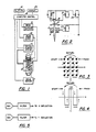
- FIG 1 which illustrates the complete system for heat treating by an electron beam in accordance with the invention
- the electron beam gun "1" fitted with a focus oil “2”, for focusing the electron beam on the work and deflection coils "3” for deflecting the beam along two mutually perpendicular axes so that the beam strikes the work to be heat treated in accordance with a predetermined program which has previously been placed in the memory of the computer control "8" by the system operator.
- the workpiece "4" is mounted upon a carriage “5" within a vacuum chamber "12” which is maintained at a low pressure suitable for the electron beam heat treating process by vacuum pumping system "11".
- Computer “8” not only controls the beam deflection program, but also controls the electron beam gun parameters of accelerating potential, beam current, focus coil current, as well as the vacuum pumping system and the servo drives which are utilized to position in sequence a batch of parts supported by a suitable holding fixture within the chamber.
- the operator would mount the parts upon a supporting fixture inside the vacuum chamber, close the door of the vacuum chamber, and initiate the functioning of the machine by pressing a "start" button.
- the computer control then takes over the operation causing the vacuum valves to be operated so that the vacuum chamber "12" in which the parts have been placed is evacuated rapidly, the electron beam gun energized, and the beam controlled so that the desired heat treat pattern is projected onto the workpiece for the desired length of time, the electron beam gun de-energized, and the next part moved into position under the electron beam gun.
- the operation is extremely fast; a ten cubic foot chamber may be pumped down in less than 30 seconds and each part heat treated in a matter of 2 or 3 seconds to provide multiple part processing at very high production rates.
- all parameters are monitored by suitable transducers and changes in the value of any of the parameters are displayed on the cathode ray oscilloscope "24".
- the computer is programmed to provide a continuous output of 2-channel X/Y coordinate information. These two output signals are provided to the input terminal of a current amplifier "9" which controls the currents in an X/ Y electro-magnetic deflection coil assembly "3".
- the deflection coil assembly "3" is used to deflect the electron beam passing through it along two mutually perpendicular axes.
- the output of the computer is used to deflect the electron beam in a program pattern for the purpose of selected surface heating.
- Figure 2 illustrates in schematic form the general arrangement of the principal elements of an electron beam gun and its associated electrical supplies.
- the elements of an electron beam gun consist of a filament "15”, a cathode “16", an anode “17”, a focus coil “2", deflection coils "3", and their associated supplies "20", "21", “22” and "23".
- Filament current supply "20” delivers current to filament “15” and brings the temperature of the filament to the level at which it is in condition to deliver electrons.
- a high-voltage power supply "22" applies a potential of 60,000 volts to anode “17" with respect to the filament "15” to cause the electrons to be accelerated towards the anode and through an aperture in the anode so as to form a beam of electrons moving at a velocity which may approach the speed of light.
- the cathode “16” and anode “17” are shaped in such a manner as to create an electrostatic field between the anode and the cathode which causes the electron beam to be directed towards a point a short distance outside of the anode.
- An adjustable DC power supply "21" of approximately 2,000 volts is applied between the filament and the -,ithode and by this means the intensity of the electron beam current may be controlled.
- the deflection coils "3" cause the beam to be deflected along two axes so as to cause the beam to impinge at a desired point upon the work.
- the output of all the various current and voltage supplies for the electron beam gun may be controlled by the computer and all may be programmed so that these values may be modified and varied so that the electron beam is caused to describe a preset pattern on the surface of the work in a given time and to repeat the pattern several times.
- Figure 3 illustrates a typical dot matrix pattern utilized in surface heat treating a local square section of a workpiece in accordance with the prior art.
- the continuous pattern of the present invention is illustrated in Figure 4 and results from processing and deflection signals which produce the dot pattern in accordance with the following method.
- the wave form of the voltages which are applied to the deflection coils of the electron beam gun, in order to form the dot matrix pattern of the old art may be translated and transformed to the wave form required to produce a continuously moving electron beam on the work surface as is illustrated in Figure 4 in the following manner:
- the voltage applied to the "Y” axis steps from “A” to “B” level to “C” level to “D” level to “E” level in order to cause the electron beam to move from “A” to “B” to “C” to “D” and to “E” as shown on Figure 3.
- the "Y” axis graph indicates a change in voltage through the steps “F”, “G”, “H”, “I” and “J”, which causes the electron beam to move upward along the "Y” axis to "F", "G", “H”, “I” and “J” spots.
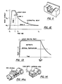
- Figure 11 illustrates a portion of a workpiece which requires the application of different amounts of energy at different points during the heat treat cycle.
- the area "A”, which is a double inside corner, would require the greatest amount of heat input because the transmission of heat away from that area will be the greatest.
- Area "B”, an inside corner, will require slightly less energy.
- Area "C”, an inside-outside corner, will require still less.
- Area "D”, an outside corner, and area “E”, open on two sides, require the least energy input.
- the temperature over the surface of the area to be heat treated may be brought to a uniform temperature throughout so that no melted spots will develop because of too high heat input or because of poor heat transmission from that particular area.
- Zone 1 is a step to a high value of beam current, I B1 , with this value of a beam current maintained for time T 1 seconds.
- Zone 2 consists of a linear downslope to a lower value of beam current, I B2 , during a time period T 2 -T 1 seconds, and Zone 3 is the exponential decay to a third current level-I B3 .
- Figure 14 is a cutaway view of a portion of the workpiece shown in Figure 14A, surface hardened by the process of the present invention.
- the power of the electron beam has ranged from 10 kW to 50 kW.
- a circular area of 1" diameter on a 1/2" plate of S.A.E. 4140 steel was hardened to 61 HRC to a case depth of .080" in two seconds.
- the total energy input required was 19,914 Watt seconds.
- discrete and localized areas on a workpiece may be case hardened to a desired depth in a matter of from one-half second to 2 seconds depending upon the depth of case required.
- the repetition rate for each pattern formed may be from 20 patterns per second to 800 patterns per second.
- Using an electron beam having a diameter of 0.1" at the work surface and with the work moving at a speed of 1 inch per second with respect to the electron gun would result in 20 patterns being generated over each inch of travel of the work, with a 50% overlap of each successive pattern.
- strips of case hardened material of a desired width and length may be formed wherever required on large machine parts.
Landscapes
- Chemical & Material Sciences (AREA)
- Engineering & Computer Science (AREA)
- Materials Engineering (AREA)
- Thermal Sciences (AREA)
- Crystallography & Structural Chemistry (AREA)
- Mechanical Engineering (AREA)
- Physics & Mathematics (AREA)
- Metallurgy (AREA)
- Organic Chemistry (AREA)
- Welding Or Cutting Using Electron Beams (AREA)
- Soy Sauces And Products Related Thereto (AREA)
- Gasification And Melting Of Waste (AREA)
- Treatment Of Sludge (AREA)
- Heat Treatment Of Articles (AREA)
Abstract
Description
- This invention relates to a method and apparatus for heat treating metal surfaces and, in particular, for surface hardening by means of an electron beam concentrated to a high power density.
- The heat treatment of metals is an important industrial process which is utilized to impart to the metal desirable properties such as toughness or hardness. For some applications, where steels are used for tools for working metals, it is necessary that the material be hardened to as great a depth as possible so that the tool retains its cutting properties so that it may be ground periodically as it wears. Steel at room temperature consists of two phases:
- (1) Ferrite, which is essentially iron that has very small amounts of dissolved carbon and alloying elements; and
- (2) Carbides, which are composed mainly of alloying elements and carbon.
- To be hardened, the steel must be heated above a certain temperature, where the ferrite transforms to another structure called austenite. The quantity of carbon which the austenite is capable of accepting depends on the temperature, and this quantity decreases as the temperature is lowered. If the austenite is quenched at a sufficiently rapid rate, the carbon is not able to precipitate out of solution and remains trapped in the structure. The trapped carbon produces a super-saturated solution in ferrite, which is called martensite. It is the capacity of the steel to keep the carbon in solution and undergo the martensitic transformation which is the important factor in hardening. There are many varieties of carbon tool steels and alloy steels each of which, when subjected to the proper heat treatment, result in a product having the desired characteristics for each specific application.
- Whereas tools for metalworking require hardness throughout the material, there are many industrial parts which require a hard, wear-resistant surface and a ductile or tough core. Surfaces of such parts are hardened by carburizing, nitriding, cyaniding, or carbo-nitriding.
- Carburizing requires that the parts be exposed to a carburizing gas at elevated temperatures for periods of about 5 to 72 hours or packed in a carburizing compound for this period. Carbon monoxide or methane is the carrier gas, and carbon dissolves in the austenite and penetrates below the surface by diffusion.
- In nitriding, the parts are heated in an ammonia atmosphere at 450 to 540 degrees centrigrade (950 to 1,000 degrees Fahrenheit) for about 8 to 96 hours. The material is hardened to a depth of up to 0,76 mm (0.03 inches).
- In cyaniding, small parts such as gears, ratchet pins and bushings are heated in a molten bath of sodium cyanide from 10 minutes to 4 hours and are then quenched in water or oil. The parts may be hardened by this method to a depth of 0,635 mm (0.025 inches).
- In the carbo-nitriding process, the parts are subjected to a gaseous atmosphere containing hydrocarbons and ammonia at a temperature of 650 to 900°C (1,200 to 1,650 degrees Fahrenheit).
- Another process by which steel parts may be hardened is the induction heating process. The parts are held adjacent to, or within a coil through which alternating current passes. High frequencies are used for small parts or for surface heating and low frequencies are utilized for heating in- depth.
- The carburizing, nitriding and cyaniding processes are awkward to apply and are time-consuming. Hardening by the use of the induction heating process requires somewhat less time and may be done on a production line basis, but requires the use of specially shaped coils for each application.
- Aside from the danger in working with noxious and poisonous gases and liquids and the production of air pollutants formed during the hardening process, all the above processes suffer from the inconvenience resulting from the parts becoming distorted during the process because they are subjected to high temperatures for long periods of time. If the parts become distorted, it becomes necessary to rework them by re-machining them to the required tolerance-a costly procedure made more costly because the parts are then in the hardened state.
- The present invention is directed to the surface heat treatment of materials at extremely high speeds and is useful in overcoming the deficiencies in the above heretofore used method of heat treating. The new heat treating process utilizes the high power density available in the electron beam, which is generated by accelerating a beam of electrons by means of a high potential electrostatic field and directing the electron beam by focusing and deflecting it along two mutually perpendicular axes so that the beam is played upon the work in a desired two-dimensional pattern. In this manner, the parts may be heat treated at several localized areas without it being necessary to bring the total mass of the part to the proper heat treating temperature. Because of this, the total energy required by this new process is only a fraction of the energy which must be utilized in the older processes for heat treating the same parts. The type of parts which lend themselves to this method of heat treating include cams, spindles, rotors, bearing races, clutch stators, piston rings, tool joint ends, ball joints, cylinder liners, turbine blades, machine tool surfaces, valve seats, etc. With this process, the localized surface to be heat treated is rapidly brought to the proper temperature, maintained for a suitable length of time, and the treated area usually self-quenched by the surrounding mass of metal in the part. There is no need for a quenching medium such as a water spray or an oil bath to be utilized. During the heat treating process, the motion of the electron beam may be under control of a mini-computer which has been programmed by the operator to control the deflection coils of the electron gun along two axes so that the beam is caused to move continuously along a desired path on a localized area on the work surface in accordance with a preset program of instantaneous velocity.
- Heretofore, surface heat treatment of metals has been effected by the method described in U.S. Patent No. 4,179,316, granted to J. D. Con- nors, et al., on December 18, 1979, and assigned to Sciaky Bros., Inc. This method utilizes an electron beam which is controlled so as to produce a desired pattern of separated points of impingement of the beam upon the work so as to form a dot matrix of spots on the work at which the beam is caused to rest for a preset period of time in sequence. In practicing this dot matrix method, it was discovered that the method could not be utilized to the best advantage inasmuch as the temperature at the points of impingement of the beam was found to be several hundred degrees greater than at those areas between points of impingement. If the current in the beam was then increased, in order to shorten the heat treatment time, it was found that hot spots were developed and local melting was experienced at the points of impingement of the beam upon the work. It was then discovered that a more uniform temperature distribution over the area intended to be surface hardened could be realized by utilizing an electron beam which was caused to move continuously over the area rather than a beam which was caused to rest for a predetermined time at an array of spots, as was done and described in U.S. Patent No. 4,179,316. It was also discovered that by continuously moving the beam, but by varying the speed of the beam in accordance with the variations of heat flow from the various sections of the area being heat treated, it was possible to obtain a uniform temperature over the full area being heat treated. In order to practice the new method, a system was devised for translating a dot matrix pattern heretofore used for heat treating a linear, continuous pattern. The heat treat matrix pattern which was defined by a set of dwell points is converted into a continuous line pattern by means of linearly interpolating digital to analog converter deflection signals. A four-pole, low pass programmable Bessel filter is utilized, and mathematically defined distribution functions are used to equalize the surface temperature. A linear interpolation circuit is used to convert a basically stationary beam at each dwell point into a continuously moving beam. In practicing the new method, one may start with a given array of dwell points, each point with a given dwell time for the electron beam. This array is formed on the surface of the workpiece by applying suitable staircase-pattern voltages, and the resulting current waves to the "X" and "Y" deflection coils of the electron beam gun cause the beam to be deflected so as to strike the work and produce a dwell raster pattern on a localized area on the surface of the work. In order to convert to a continuously moving beam, the staircase pattern for the "X" and "Y" deflection coils is processed by linear interpolation from step to step to produce a smoothly varying deflection signal. When the filtered voltage patterns are applied to the "X" and "Y" deflection coils, the result will be a continuously moving electron beam impinging upon the work surface rather than an array of hot spots caused by an intermittent motion of the beam from spot to spot, with the beam resting at each spot for a preset period of time. By means of linear interpolation, the staircase deflection voltage, creating a series of stationary beam positions, has been transformed into a continuously moving electron beam. The continuous path of the electron beam, in accordance with the new invention, may be viewed on a cathode ray oscilloscope. It is the object of this invention to produce a uniform depth of case hardness over a given surface.
- Another object of this invention is to perform the surface heat treatment over localized areas of intricately shaped parts with the least expenditure of energy and time.
- Another object of the invention is to produce a continuously moving electron beam from an intermittently moving beam which produces a pattern of discrete heat spots upon a work surface over a localized area of that workpiece.
- Another object of the invention is to produce a rapid rise in temperature over a localized area of a workpiece.
- Another object is to produce a uniform temperature over a localized area of a workpiece.
- Another object is to transform a dot matrix pattern of dwell points for the electron beam on a work surface to a continuously moving electron beam on the work surface.
- Another object is to produce a continuously moving electron beam whose velocity with respect to the work surface at the point of impingement of the beam and that work surface is varied in accordance with the law of thermal heat flow from the point of impingement of the electron beam, as that thermal conduction varies from point to point and with time, so as to produce a uniform temperature over the surface being treated.
- Another object of the invention is to surface harden a workpiece with a minimum of distortion resulting in the workpiece due to the hardening process.
- The invention is defined in the appended claims.
- The objects and advantages of the invention will become more apparent in view of the following detailed description taken in conjunction with the drawings described below:
- Figure 1 is a block diagram showing the essential elements of the apparatus in accordance with this invention.
- Figure 2 is a schematic drawing of the essential elements of an electron beam gun and its power supply.
- Figure 3 illustrates a heat treat pattern utilized in the old process of heat treating by means of an electron beam, which is programmed to define a series of spots at which the beam dwells for a given period at each of the points identified by the letters "A" through "T".
- Figure 4 illustrates the pattern of motion of the beam at the point at which it strikes the surface of the workpiece in accordance with the new method.
- Figure 5 is a block diagram illustrating the method by which the stepped electron beam motion represented by the dot pattern of Figure 3 is transformed to the continuous electron beam motion represented by Figure 4.
- Figure 6 shows a staircase voltage pattern for "Y" axis deflection which may be transformed to the voltage pattern of Figure 7 in order to produce a continuous path pattern from a dot pattern over a triangular area.
- Figures 8 and 9 illustrate respectively a dot pattern and its continuous spiral path counterpart.
- Figure 10 shows graphically, by solid line, the pattern of voltages with respect to time which must be applied to the "X" and "Y" deflection coils in order to produce the stepped changes in position illustrated in Figure 3 and shows, by broken lines, the pattern of voltages that must be applied to the "X" and "Y" deflection coils to cause the electron beam to follow the continuous pattern illustrated in Figure 4.
- Figure 11 illustrates a portion of a workpiece which requires the application of different values of electron beam powers at different areas of the surface being treated.
- Figure 12 illustrates a program of variation in electron beam power with respect to the time which has been found to be most effective in practicing the new process.
- Figure 13 illustrates the temperature changes on the surface being treated.
- Figure 14 is a macrograph of a heat treated section of the workpiece.
- Referring now to Figure 1, which illustrates the complete system for heat treating by an electron beam in accordance with the invention we may note the electron beam gun "1" fitted with a focus oil "2", for focusing the electron beam on the work and deflection coils "3" for deflecting the beam along two mutually perpendicular axes so that the beam strikes the work to be heat treated in accordance with a predetermined program which has previously been placed in the memory of the computer control "8" by the system operator. The workpiece "4" is mounted upon a carriage "5" within a vacuum chamber "12" which is maintained at a low pressure suitable for the electron beam heat treating process by vacuum pumping system "11". The motion of carriage "5" is effected along several axes of required motion by means of servo motor "6" which is controlled by servo drive "7". The motor positions the carriage within the chamber so that the work will be properly positioned with respect to the resting position of the electron beam "13" which is deflected by the action of the magnetic fields of the "X" and "Y" axis deflection coils which are under control of beam deflection amplifiers "9", which in turn are controlled by information previously stored in the computer control memory. Computer "8" not only controls the beam deflection program, but also controls the electron beam gun parameters of accelerating potential, beam current, focus coil current, as well as the vacuum pumping system and the servo drives which are utilized to position in sequence a batch of parts supported by a suitable holding fixture within the chamber. In order to heat treat a batch of parts, the operator would mount the parts upon a supporting fixture inside the vacuum chamber, close the door of the vacuum chamber, and initiate the functioning of the machine by pressing a "start" button. The computer control then takes over the operation causing the vacuum valves to be operated so that the vacuum chamber "12" in which the parts have been placed is evacuated rapidly, the electron beam gun energized, and the beam controlled so that the desired heat treat pattern is projected onto the workpiece for the desired length of time, the electron beam gun de-energized, and the next part moved into position under the electron beam gun. The operation is extremely fast; a ten cubic foot chamber may be pumped down in less than 30 seconds and each part heat treated in a matter of 2 or 3 seconds to provide multiple part processing at very high production rates. In addition to controlling the operation of the machine functions, all parameters are monitored by suitable transducers and changes in the value of any of the parameters are displayed on the cathode ray oscilloscope "24". By means of a teletype "14" or other input device, the computer is programmed to provide a continuous output of 2-channel X/Y coordinate information. These two output signals are provided to the input terminal of a current amplifier "9" which controls the currents in an X/ Y electro-magnetic deflection coil assembly "3". The deflection coil assembly "3" is used to deflect the electron beam passing through it along two mutually perpendicular axes. Thus, the output of the computer is used to deflect the electron beam in a program pattern for the purpose of selected surface heating. In previous attempts at electron beam heat treating, square, triangular and parabolic wave shapes of various frequencies were fed to the "X" and "Y" deflection coils of the electron beam gun system in order to cause the beam to sweep the surface of the work in accordance with the Lissajou patterns formed by the application of these signals to the deflection coils. The patterns developed on the work proved to be unsatisfactory and limited in application. The use of a computer to control directly the position of the electron beam provides infinitely variable control of average electron beam power and in the distribution of the electron beam power over the desired surface.
- The advantages of computer controlled deflection over the previously tried methods are several:
- (1) When projecting the Lissajou pattern upon the work surface, inherently there result many crossover points and consequently, over temperature conditions occur at these points. With computer controlled deflection, beam path crossover points are eliminated. The rate of surface heating can, therefore, be more rapid and accurately controlled since the energy delivered by the electron beam to the surface of the work is continuous along the path described by the beam along the work.
- (2) The average beam power density can be very accurately controlled to provide heat inputs necessary for complex part geometries such as gears and cams.
- (3) Using computer memory or other storage devices such as paper tape, magnetic drums or tape, pattern information for a variety of heat treating requirements can be stored for rapid recall and application.
- (4) More sophisticated computer programs can be used to alter continuously the average power in the deflected beam so that complex geometries such as gears may be heat treated by rotation of the gear beneath the deflected beam.
- (5) Deflection pattern information in the computer may be used to program other memory devices such as electronic memories which will provide pattern output signals and allow the computer to be used for other machine functions.
- Figure 2 illustrates in schematic form the general arrangement of the principal elements of an electron beam gun and its associated electrical supplies. The elements of an electron beam gun consist of a filament "15", a cathode "16", an anode "17", a focus coil "2", deflection coils "3", and their associated supplies "20", "21", "22" and "23". Filament current supply "20" delivers current to filament "15" and brings the temperature of the filament to the level at which it is in condition to deliver electrons. A high-voltage power supply "22" applies a potential of 60,000 volts to anode "17" with respect to the filament "15" to cause the electrons to be accelerated towards the anode and through an aperture in the anode so as to form a beam of electrons moving at a velocity which may approach the speed of light. The cathode "16" and anode "17" are shaped in such a manner as to create an electrostatic field between the anode and the cathode which causes the electron beam to be directed towards a point a short distance outside of the anode. An adjustable DC power supply "21" of approximately 2,000 volts is applied between the filament and the -,ithode and by this means the intensity of the electron beam current may be controlled. Increasing the negative potential on the cathode with respect to the filament reduces the electron beam current and vice versa. Beyond the opening in the anode there exists a field free space through which the beam passes through the focus coil "2" where it is focused to a desired spot on a workpiece by adjusting the focus current applied to the focus coil by power supply "23". Directly below the focus coil, the deflection coils "3" cause the beam to be deflected along two axes so as to cause the beam to impinge at a desired point upon the work. The output of all the various current and voltage supplies for the electron beam gun may be controlled by the computer and all may be programmed so that these values may be modified and varied so that the electron beam is caused to describe a preset pattern on the surface of the work in a given time and to repeat the pattern several times.
- Figure 3 illustrates a typical dot matrix pattern utilized in surface heat treating a local square section of a workpiece in accordance with the prior art. The continuous pattern of the present invention is illustrated in Figure 4 and results from processing and deflection signals which produce the dot pattern in accordance with the following method. The wave form of the voltages which are applied to the deflection coils of the electron beam gun, in order to form the dot matrix pattern of the old art (as shown in Figure 3, for example) may be translated and transformed to the wave form required to produce a continuously moving electron beam on the work surface as is illustrated in Figure 4 in the following manner:
- Referring first to Figure 10, we see here graphically in solid lines the pattern of voltages with respect to time which must be applied respectively to the "X" and "Y" deflection coils in order to produce the stepped changes in position illustrated in Figure 3 and by the broken lines of Figure 10, the pattern of voltages that must be applied to the "X" and "Y" deflection coils to cause the electron beam to follow the continuous pattern illustrated in Figure 4. On the solid line graph illustrated to the right of "Y" the various steps indicated by the letters "A", "B", "C", etc., refer to the stepped voltages which are applied to the "Y" axis deflection amplifier for a period of time indicated by the length of each step, and the solid line above the "X" indicates the stepped voltages which are applied to the "X" axis deflection amplifier, each step being applied for a time indicated by the length of the step. During the first step which defines the voltage applied to the "X" axis, the voltage applied to the "Y" axis steps from "A" to "B" level to "C" level to "D" level to "E" level in order to cause the electron beam to move from "A" to "B" to "C" to "D" and to "E" as shown on Figure 3. With the change in voltage to the second step shown on the "X" axis graph, the "Y" axis graph indicates a change in voltage through the steps "F", "G", "H", "I" and "J", which causes the electron beam to move upward along the "Y" axis to "F", "G", "H", "I" and "J" spots. As the voltages change in accordance with the stepped changes on the "X" and "Y" graphs, the electron beam is caused to move from "K" to "L", etc., to "T" and then, as the voltage changes depicted on the graphs repeat themselves, the electron beam repeats the motion and formation of the spot or dot pattern on the work. In practicing the new process, the voltages applied to the "X" and "Y" axis deflection amplifiers are those illustrated by the dotted line, which voltages (when applied to their respective "X" and "Y" deflection amplifiers, will produce the motion shown in Figure 4 from start to finish. The last- mentioned "X" and "Y" deflection signals (the smooth, continuous curves) are derived from the staircase type curves or voltage patterns in the following manner:
- The analog signals representing the "X" and "Y" deflection voltages are delivered from a digital to analog conversion unit to a filter, preferably a four-pole, low pass Bessel filter, which linearly interpolates the wave form fed to it-that is, those illustrated by the solid curves of Figure 10-to form the curves shown graphically in Figure 10 by the dotted or broken lines. The resulting filtered wave forms are applied to the deflection amplifiers.
- Figure 11 illustrates a portion of a workpiece which requires the application of different amounts of energy at different points during the heat treat cycle. The area "A", which is a double inside corner, would require the greatest amount of heat input because the transmission of heat away from that area will be the greatest. Area "B", an inside corner, will require slightly less energy. Area "C", an inside-outside corner, will require still less. Area "D", an outside corner, and area "E", open on two sides, require the least energy input. By proportioning the energy input in this fashion, the temperature over the surface of the area to be heat treated may be brought to a uniform temperature throughout so that no melted spots will develop because of too high heat input or because of poor heat transmission from that particular area.
- It has been found that the most effective and most rapidly accomplished heat treating is produced by applying a varying current at a fixed accelerating potential to the electron beam during the heat treat cycle. The wave form found to be most effective is the one illustrated in Figure 12. The curve illustrates a three-zone current vs. time program. Zone 1 is a step to a high value of beam current, IB1, with this value of a beam current maintained for time T1 seconds.
Zone 2 consists of a linear downslope to a lower value of beam current, IB2, during a time period T2-T1 seconds, andZone 3 is the exponential decay to a third current level-IB3. The application of this current wave form to the electron beam results in a temperature profile as illustrated in Figure 13, which shows that the temperature rises to its proper value or desired value in less than .2 to .3 seconds and is maintained at this level until the material is properly treated, after which the current is turned off and the temperature allowed to decay asymptotically to the workpiece body temperature. - Figure 14 is a cutaway view of a portion of the workpiece shown in Figure 14A, surface hardened by the process of the present invention.
- A variety of workpieces requiring localized case hardened areas having various shapes and sizes have been successfully case hardened by the new process. The power of the electron beam has ranged from 10 kW to 50 kW. For example, a circular area of 1" diameter on a 1/2" plate of S.A.E. 4140 steel was hardened to 61 HRC to a case depth of .080" in two seconds. The total energy input required was 19,914 Watt seconds.
- This remarkable result is due to raising the temperature of a thin layer at the surface from 60°F. to close to 2,700°F. in 200 milliseconds by means of the high power density inherent in the electron beam, maintaining this temperature in the desired volume for a preset period, and then rapidly quenching this volume by the cool underlying material of the workpiece. A uniform rapid rise in temperature over the area being treated is obtained by moving the electron beam in continuous fashion along a prearranged path over a portion of the surface of the workpiece.
- By means of the above process, discrete and localized areas on a workpiece may be case hardened to a desired depth in a matter of from one-half second to 2 seconds depending upon the depth of case required.
- There are other applications for surface heat treating; for example, the ways of a lathe or the periphery of a roller bearing or the periphery of cams used in gasoline engines, etc., which require surface heat treatment along a path which may be .5" to 1" wide and extend for several inches or as much as several feet. The present process has been utilized for such purposes by applying an electron beam to a workpiece so that it moves continuously in a desired pattern as described above over, for example, an area of dimensions 1"x1" and at the same time moving the workpiece with respect to the electron gun so that a series of overlapping patterns are formed on the work by the impingement of the beam on the moving workpiece. In this manner a path 1" wide of a desired length would be surface treated by the beam. The repetition rate for each pattern formed may be from 20 patterns per second to 800 patterns per second. Using an electron beam having a diameter of 0.1" at the work surface and with the work moving at a speed of 1 inch per second with respect to the electron gun would result in 20 patterns being generated over each inch of travel of the work, with a 50% overlap of each successive pattern.
- By the above means, strips of case hardened material of a desired width and length may be formed wherever required on large machine parts.
Claims (10)
Applications Claiming Priority (2)
| Application Number | Priority Date | Filing Date | Title |
|---|---|---|---|
| US514866 | 1983-07-18 | ||
| US06/514,866 US4486240A (en) | 1983-07-18 | 1983-07-18 | Method and apparatus for heat treating |
Publications (3)
| Publication Number | Publication Date |
|---|---|
| EP0151165A1 EP0151165A1 (en) | 1985-08-14 |
| EP0151165A4 EP0151165A4 (en) | 1986-07-08 |
| EP0151165B1 true EP0151165B1 (en) | 1988-08-31 |
Family
ID=24048995
Family Applications (1)
| Application Number | Title | Priority Date | Filing Date |
|---|---|---|---|
| EP84902844A Expired EP0151165B1 (en) | 1983-07-18 | 1984-06-11 | Improvement in method and apparatus for heat treating |
Country Status (6)
| Country | Link |
|---|---|
| US (1) | US4486240A (en) |
| EP (1) | EP0151165B1 (en) |
| JP (1) | JPS60501865A (en) |
| AU (1) | AU566609B2 (en) |
| DE (1) | DE3473772D1 (en) |
| WO (1) | WO1985000622A1 (en) |
Families Citing this family (20)
| Publication number | Priority date | Publication date | Assignee | Title |
|---|---|---|---|---|
| US4562332A (en) * | 1984-03-26 | 1985-12-31 | Rockwell International Corporation | Surface crack healing with high-energy beam |
| US4729802A (en) * | 1986-01-16 | 1988-03-08 | J. I. Case Company | Opener-disk heat-treating process and product |
| FR2599640B1 (en) * | 1986-06-05 | 1993-01-22 | Turbomeca | HIGH ENERGY DENSITY LOCALIZED VOLUME PROCESSING AND PRODUCTS THEREOF |
| GB8921475D0 (en) * | 1989-09-22 | 1989-11-08 | Gen Electric Co Plc | High current switch components |
| ES2034888B1 (en) * | 1991-07-11 | 1994-02-16 | Madaus Cerafarm Lab | PROCEDURE FOR OBTAINING THE TOTAL ACID FRACTION OF THE LIPID EXTRACTS OF THE FRUITS OF THE SABAL SERRULATA. |
| DE19500091C1 (en) * | 1995-01-04 | 1996-04-04 | Dyckerhoff & Widmann Ag | Predetermined rupture position prodn. on tensile member of insert anchor |
| JPH093528A (en) * | 1995-04-17 | 1997-01-07 | Aisin Aw Co Ltd | Treatment for surface of steel member and surface treated steel member |
| JP3541490B2 (en) * | 1995-04-17 | 2004-07-14 | アイシン・エィ・ダブリュ株式会社 | Torque converter |
| US6305078B1 (en) * | 1996-02-16 | 2001-10-23 | Hitachi, Ltd. | Method of making a turbine blade |
| CA2268649C (en) * | 1996-10-15 | 2002-10-01 | Zenith Sintered Products, Inc. | Surface densification of machine components made by powder metallurgy |
| US5975569A (en) * | 1997-11-03 | 1999-11-02 | Illinois Tool Works | Heat treated combustion chamber housing and process for making same |
| AT407401B (en) * | 1998-09-18 | 2001-03-26 | Inocon Technologie Gmbh | Process for hardening surfaces |
| US6344098B1 (en) * | 2000-12-08 | 2002-02-05 | General Electric Company | High strength steam turbine rotor and methods of fabricating the rotor without increased stress corrosion cracking |
| US6933509B1 (en) * | 2001-09-11 | 2005-08-23 | Allasso Industries, Inc. | Apparatus and method using fractionated irradiation to harden metal |
| US6761851B1 (en) | 2001-09-11 | 2004-07-13 | Allasso Industries, Inc. | Apparatus and method for hardening metal by varying the engagement between irradiation and metal |
| US6750459B1 (en) | 2001-09-11 | 2004-06-15 | Allasso Industries, Inc. | Apparatus and method using irradiation to harden metal |
| DE102005038732A1 (en) * | 2005-08-15 | 2007-02-22 | Eickhorn, Geb. Fischer, Annette | Marking of metallic objects |
| US7358466B1 (en) | 2006-01-12 | 2008-04-15 | General Electric Company | Localized heat treating apparatus for blisk airfoils |
| CN100406582C (en) * | 2006-03-16 | 2008-07-30 | 中国航空工业第一集团公司北京航空材料研究院 | Electron beam surface hardening method based on point-by-point scanning |
| KR101694324B1 (en) * | 2015-12-18 | 2017-01-10 | 한국생산기술연구원 | Surface heat treatment by electron beam |
Family Cites Families (8)
| Publication number | Priority date | Publication date | Assignee | Title |
|---|---|---|---|---|
| DE2013674B2 (en) * | 1970-03-21 | 1974-03-07 | Steigerwald Strahltechnik Gmbh, 8000 Muenchen | Process for hardening workpieces, such as tools, by means of an energy beam |
| DE2018793B2 (en) * | 1970-04-20 | 1974-03-28 | Steigerwald Strahltechnik Gmbh, 8000 Muenchen | Process for the partial hardening of workpieces or tools |
| DE2037108A1 (en) * | 1970-07-27 | 1972-02-03 | Steigerwald Strahltech | Electron beam surface hardening - with fast moving workpiece relative to stationary or oscillating electron beam |
| US3802927A (en) * | 1970-09-14 | 1974-04-09 | N Gomada | Apex seal for rotary piston engine and method of producing same |
| JPS4825290A (en) * | 1971-08-04 | 1973-04-02 | ||
| US4179316A (en) * | 1977-10-17 | 1979-12-18 | Sciaky Bros., Inc. | Method and apparatus for heat treating |
| US4199689A (en) * | 1977-12-21 | 1980-04-22 | Tokyo Shibaura Denki Kabushiki Kaisha | Electron beam exposing method and electron beam apparatus |
| WO1982001016A1 (en) * | 1980-09-11 | 1982-04-01 | Sciaky Bros | Method and apparatus for surface hardening cams |
-
1983
- 1983-07-18 US US06/514,866 patent/US4486240A/en not_active Expired - Fee Related
-
1984
- 1984-06-11 JP JP59502833A patent/JPS60501865A/en active Pending
- 1984-06-11 WO PCT/US1984/000891 patent/WO1985000622A1/en not_active Ceased
- 1984-06-11 DE DE8484902844T patent/DE3473772D1/en not_active Expired
- 1984-06-11 EP EP84902844A patent/EP0151165B1/en not_active Expired
- 1984-06-11 AU AU32104/84A patent/AU566609B2/en not_active Ceased
Also Published As
| Publication number | Publication date |
|---|---|
| WO1985000622A1 (en) | 1985-02-14 |
| DE3473772D1 (en) | 1988-10-06 |
| AU3210484A (en) | 1985-03-04 |
| US4486240A (en) | 1984-12-04 |
| EP0151165A1 (en) | 1985-08-14 |
| AU566609B2 (en) | 1987-10-22 |
| EP0151165A4 (en) | 1986-07-08 |
| JPS60501865A (en) | 1985-10-31 |
Similar Documents
| Publication | Publication Date | Title |
|---|---|---|
| AU566609B2 (en) | Improvement in method and apparatus for heat treating | |
| US4179316A (en) | Method and apparatus for heat treating | |
| US3952180A (en) | Cladding | |
| US4015100A (en) | Surface modification | |
| US4539461A (en) | Method and apparatus for laser gear hardening | |
| IL46078A (en) | Method of case-alloying metals such as steel or cast iron | |
| EP0068017A4 (en) | Method of electron beam welding. | |
| JPS6293028A (en) | Bending method for plate stock by laser | |
| EP0060257B1 (en) | Method for surface hardening cams | |
| DE2111183B2 (en) | Process and arrangement for the two-stage surface hardening of workpieces made of hardenable iron and steel alloys | |
| Zenker et al. | Electron beam surface hardening | |
| AU540724B2 (en) | Method and apparatus for surface hardening cams | |
| CN2128251Y (en) | Die cast ram through laser surface treatment | |
| Alnusirat | Application of Laser Radiation for Intensification of Chemical Heat Treatment | |
| Hanson | Electron beam surface hardening utilizing computer control | |
| US7049539B2 (en) | Method for surface treating a die by electron beam irradiation and a die treated thereby | |
| US3631698A (en) | Method and apparatus for hot straightening elongated metal workpieces | |
| Zenker | Electron beam surface modification state of the art | |
| Schiller et al. | Thermal surface modification by electron beam high-speed scanning | |
| Veronesi et al. | Laser hardening of steel sintered parts | |
| Xu et al. | Pulsed laser surface hardening of ferrous alloys | |
| Kurochkin et al. | Technology for surface hardening of parts by treatment with concentrated energy flux | |
| Scarpellini et al. | Ultra Large Bearings: a complete range of seamless induction heating solutions | |
| Powers | Electron beam materials processing | |
| GB1104102A (en) | Improvements in or relating to processes and apparatus for surface-hardening hardenable steels |
Legal Events
| Date | Code | Title | Description |
|---|---|---|---|
| PUAI | Public reference made under article 153(3) epc to a published international application that has entered the european phase |
Free format text: ORIGINAL CODE: 0009012 |
|
| 17P | Request for examination filed |
Effective date: 19840913 |
|
| AK | Designated contracting states |
Kind code of ref document: A1 Designated state(s): BE DE FR GB NL SE Designated state(s): BE DE FR GB NL SE |
|
| A4 | Supplementary search report drawn up and despatched |
Effective date: 19860708 |
|
| 17Q | First examination report despatched |
Effective date: 19871104 |
|
| GRAA | (expected) grant |
Free format text: ORIGINAL CODE: 0009210 |
|
| AK | Designated contracting states |
Kind code of ref document: B1 Designated state(s): BE DE FR GB NL SE |
|
| REF | Corresponds to: |
Ref document number: 3473772 Country of ref document: DE Date of ref document: 19881006 |
|
| ET | Fr: translation filed | ||
| PLBE | No opposition filed within time limit |
Free format text: ORIGINAL CODE: 0009261 |
|
| STAA | Information on the status of an ep patent application or granted ep patent |
Free format text: STATUS: NO OPPOSITION FILED WITHIN TIME LIMIT |
|
| 26N | No opposition filed | ||
| PGFP | Annual fee paid to national office [announced via postgrant information from national office to epo] |
Ref country code: FR Payment date: 19910523 Year of fee payment: 8 Ref country code: DE Payment date: 19910523 Year of fee payment: 8 |
|
| PGFP | Annual fee paid to national office [announced via postgrant information from national office to epo] |
Ref country code: SE Payment date: 19910527 Year of fee payment: 8 |
|
| PGFP | Annual fee paid to national office [announced via postgrant information from national office to epo] |
Ref country code: BE Payment date: 19910530 Year of fee payment: 8 |
|
| PGFP | Annual fee paid to national office [announced via postgrant information from national office to epo] |
Ref country code: GB Payment date: 19910603 Year of fee payment: 8 |
|
| PGFP | Annual fee paid to national office [announced via postgrant information from national office to epo] |
Ref country code: NL Payment date: 19910630 Year of fee payment: 8 |
|
| PG25 | Lapsed in a contracting state [announced via postgrant information from national office to epo] |
Ref country code: GB Effective date: 19920611 |
|
| PG25 | Lapsed in a contracting state [announced via postgrant information from national office to epo] |
Ref country code: SE Effective date: 19920612 |
|
| PG25 | Lapsed in a contracting state [announced via postgrant information from national office to epo] |
Ref country code: BE Effective date: 19920630 |
|
| BERE | Be: lapsed |
Owner name: SCIAKY BROS. INC. Effective date: 19920630 |
|
| PG25 | Lapsed in a contracting state [announced via postgrant information from national office to epo] |
Ref country code: NL Effective date: 19930101 |
|
| GBPC | Gb: european patent ceased through non-payment of renewal fee |
Effective date: 19920611 |
|
| NLV4 | Nl: lapsed or anulled due to non-payment of the annual fee | ||
| PG25 | Lapsed in a contracting state [announced via postgrant information from national office to epo] |
Ref country code: FR Effective date: 19930226 |
|
| PG25 | Lapsed in a contracting state [announced via postgrant information from national office to epo] |
Ref country code: DE Effective date: 19930302 |
|
| REG | Reference to a national code |
Ref country code: FR Ref legal event code: ST |
|
| EUG | Se: european patent has lapsed |
Ref document number: 84902844.4 Effective date: 19930109 |