EP0148877B1 - Paper currency dispenser apparatus - Google Patents
Paper currency dispenser apparatus Download PDFInfo
- Publication number
- EP0148877B1 EP0148877B1 EP84902490A EP84902490A EP0148877B1 EP 0148877 B1 EP0148877 B1 EP 0148877B1 EP 84902490 A EP84902490 A EP 84902490A EP 84902490 A EP84902490 A EP 84902490A EP 0148877 B1 EP0148877 B1 EP 0148877B1
- Authority
- EP
- European Patent Office
- Prior art keywords
- note
- feed roller
- stack
- friction
- notes
- Prior art date
- Legal status (The legal status is an assumption and is not a legal conclusion. Google has not performed a legal analysis and makes no representation as to the accuracy of the status listed.)
- Expired
Links
Images

Classifications
-
- B—PERFORMING OPERATIONS; TRANSPORTING
- B65—CONVEYING; PACKING; STORING; HANDLING THIN OR FILAMENTARY MATERIAL
- B65H—HANDLING THIN OR FILAMENTARY MATERIAL, e.g. SHEETS, WEBS, CABLES
- B65H7/00—Controlling article feeding, separating, pile-advancing, or associated apparatus, to take account of incorrect feeding, absence of articles, or presence of faulty articles
- B65H7/02—Controlling article feeding, separating, pile-advancing, or associated apparatus, to take account of incorrect feeding, absence of articles, or presence of faulty articles by feelers or detectors
- B65H7/06—Controlling article feeding, separating, pile-advancing, or associated apparatus, to take account of incorrect feeding, absence of articles, or presence of faulty articles by feelers or detectors responsive to presence of faulty articles or incorrect separation or feed
- B65H7/12—Controlling article feeding, separating, pile-advancing, or associated apparatus, to take account of incorrect feeding, absence of articles, or presence of faulty articles by feelers or detectors responsive to presence of faulty articles or incorrect separation or feed responsive to double feed or separation
-
- B—PERFORMING OPERATIONS; TRANSPORTING
- B65—CONVEYING; PACKING; STORING; HANDLING THIN OR FILAMENTARY MATERIAL
- B65H—HANDLING THIN OR FILAMENTARY MATERIAL, e.g. SHEETS, WEBS, CABLES
- B65H3/00—Separating articles from piles
- B65H3/02—Separating articles from piles using friction forces between articles and separator
- B65H3/06—Rollers or like rotary separators
- B65H3/0638—Construction of the rollers or like rotary separators
-
- B—PERFORMING OPERATIONS; TRANSPORTING
- B65—CONVEYING; PACKING; STORING; HANDLING THIN OR FILAMENTARY MATERIAL
- B65H—HANDLING THIN OR FILAMENTARY MATERIAL, e.g. SHEETS, WEBS, CABLES
- B65H3/00—Separating articles from piles
- B65H3/02—Separating articles from piles using friction forces between articles and separator
- B65H3/06—Rollers or like rotary separators
- B65H3/0653—Rollers or like rotary separators for separating substantially vertically stacked articles
-
- G—PHYSICS
- G07—CHECKING-DEVICES
- G07D—HANDLING OF COINS OR VALUABLE PAPERS, e.g. TESTING, SORTING BY DENOMINATIONS, COUNTING, DISPENSING, CHANGING OR DEPOSITING
- G07D11/00—Devices accepting coins; Devices accepting, dispensing, sorting or counting valuable papers
- G07D11/10—Mechanical details
-
- B—PERFORMING OPERATIONS; TRANSPORTING
- B65—CONVEYING; PACKING; STORING; HANDLING THIN OR FILAMENTARY MATERIAL
- B65H—HANDLING THIN OR FILAMENTARY MATERIAL, e.g. SHEETS, WEBS, CABLES
- B65H2404/00—Parts for transporting or guiding the handled material
- B65H2404/50—Surface of the elements in contact with the forwarded or guided material
- B65H2404/53—Surface of the elements in contact with the forwarded or guided material with particular mechanical, physical properties
- B65H2404/531—Surface of the elements in contact with the forwarded or guided material with particular mechanical, physical properties particular coefficient of friction
- B65H2404/5311—Surface with different coefficients of friction
-
- B—PERFORMING OPERATIONS; TRANSPORTING
- B65—CONVEYING; PACKING; STORING; HANDLING THIN OR FILAMENTARY MATERIAL
- B65H—HANDLING THIN OR FILAMENTARY MATERIAL, e.g. SHEETS, WEBS, CABLES
- B65H2511/00—Dimensions; Position; Numbers; Identification; Occurrences
- B65H2511/10—Size; Dimensions
- B65H2511/13—Thickness
-
- B—PERFORMING OPERATIONS; TRANSPORTING
- B65—CONVEYING; PACKING; STORING; HANDLING THIN OR FILAMENTARY MATERIAL
- B65H—HANDLING THIN OR FILAMENTARY MATERIAL, e.g. SHEETS, WEBS, CABLES
- B65H2511/00—Dimensions; Position; Numbers; Identification; Occurrences
- B65H2511/20—Location in space
-
- B—PERFORMING OPERATIONS; TRANSPORTING
- B65—CONVEYING; PACKING; STORING; HANDLING THIN OR FILAMENTARY MATERIAL
- B65H—HANDLING THIN OR FILAMENTARY MATERIAL, e.g. SHEETS, WEBS, CABLES
- B65H2511/00—Dimensions; Position; Numbers; Identification; Occurrences
- B65H2511/50—Occurence
- B65H2511/52—Defective operating conditions
- B65H2511/524—Multiple articles, e.g. double feed
-
- B—PERFORMING OPERATIONS; TRANSPORTING
- B65—CONVEYING; PACKING; STORING; HANDLING THIN OR FILAMENTARY MATERIAL
- B65H—HANDLING THIN OR FILAMENTARY MATERIAL, e.g. SHEETS, WEBS, CABLES
- B65H2513/00—Dynamic entities; Timing aspects
- B65H2513/40—Movement
- B65H2513/41—Direction of movement
- B65H2513/412—Direction of rotation of motor powering the handling device
-
- B—PERFORMING OPERATIONS; TRANSPORTING
- B65—CONVEYING; PACKING; STORING; HANDLING THIN OR FILAMENTARY MATERIAL
- B65H—HANDLING THIN OR FILAMENTARY MATERIAL, e.g. SHEETS, WEBS, CABLES
- B65H2553/00—Sensing or detecting means
- B65H2553/60—Details of intermediate means between the sensing means and the element to be sensed
- B65H2553/61—Mechanical means, e.g. contact arms
-
- B—PERFORMING OPERATIONS; TRANSPORTING
- B65—CONVEYING; PACKING; STORING; HANDLING THIN OR FILAMENTARY MATERIAL
- B65H—HANDLING THIN OR FILAMENTARY MATERIAL, e.g. SHEETS, WEBS, CABLES
- B65H2701/00—Handled material; Storage means
- B65H2701/10—Handled articles or webs
- B65H2701/19—Specific article or web
- B65H2701/1912—Banknotes, bills and cheques or the like
Definitions
- This invention relates to an apparatus for dispensing paper notes from a banking machine or the like and constitutes improvements on machines disclosed in United States Patent No. 4,154,437 and United States Patent No. 4,355,797.
- the present invention relates particularly to an automatic banking or teller machine (ATM) and, more particularly, to ATMs which may be installed in free-standing locations either remote from central banks or at locations accessible to customers in or adjacent central banks for dispensing paper currency or notes of one or more denominations.
- ATM automatic banking or teller machine
- the invention relates to an apparatus incorporating a friction picker mechanism of simple construction for reliably feeding paper notes one at a time from a supply stack of notes. Further, the invention relates to an apparatus incorporating a friction picker mechanism which eliminates complicated pneumatic or suction picker components the machine combining this friction picker mechanism with known doubles detecting components; thus, the invention eliminates diversion of doubles, when detected, from a.
- the invention eliminates transport means for delivering detected doubles to a divert container; the invention eliminates a divert container for receiving detected doubles and security devices therefor; the invention eliminates belt conveyers or like transport devices as a part or component of the friction picker mechanism; and the invention permits delivery of picked notes being dispensed directly to a delivery station which may be an access opening in the fascia of an ATM.
- the invention relates to an apparatus which simplifies note timing as a part of the feeding of notes one at a time from a note supply stack to a delivery station with controlled spacing of the notes more consistently than is present in prior ATM note dispensers.
- the invention relates to an apparatus incorporating a new friction picker mechanism concept wherein detected doubles are returned by the friction picker mechanism to the supply stack of notes for separation and redispensing.
- the invention relates to an apparatus in which servicing and maintenance are simplified because of the simple and reliable construction and operation of the apparatus all of which significantly reduce the costs of manufacture, repair and maintenance.
- the invention relates to an automated paper note teller or dispenser machine which is characterized by having all of the features described combined in a cooperative and interrelated manner.
- picker mechanisms are known in various arts for feeding sheets, documents, currency and the like, from a stack thereof to another location.
- picker mechanisms for ATMs which pick notes from a stack and deliver the notes one at a time to a customer delivery station have been pneumatic or suction type picker devices, such as disclosed in United States Patent No. 4,355,797 for example.
- suction picker devices are complicated in construction and operation, they have many parts or components, and they may be relatively slow in operation. It is, thus, desirable to avoid the complicated struction and complicated and slow operation of suction picker devices.
- Other sheet, document or currency picker devices have involved friction members which pull or wipe sheets from a stack thereof to feed the sheets to a downstream location.
- Still other picker devices include components which push the outer °document from the stack to move a downstream end of the document to a feed roll stand. Sometimes the downstream end of the pushed document has been retarded to separate the document from the next document in the stack.
- This push-retard picker may be used where the paper or document is still and does not crumple under push-retard pressure. Such procedure cannot be used in picking paper notes since they are not still enough to avoid being crumpled or crushed when handled by push-retard means.
- a flexible belt strips the outer piece to be fed from the lower end of a stack of envelopes under pressure to push the piece forward where a counter-rotating roll retards such movement before the piece reaches a feed means roll stand including one of the belt conveyor rolls, to prevent the feeding of more than one piece.
- a belt conveyor component is required as a part of the picking and feeding mechanism.
- That patent discloses an automated paper note teller or dispenser machine of a type in which notes at the end of a note supply stack, normally pressed toward a friction picker mechanism, are separated and picked, normally one at a time, from the stack by associated friction areas of a rotatable feed roller which forms part of the friction picker mechanism and which has a cylindrical surface, provided with an arcuate rubber friction segment means, for contacting one face of the notes; the machine also including a rubber friction separator means directed toward, and free of contact with, the feed roller, the friction separator means engaging the otherface of, and resisting movement of, the notes being fed as the notes are driven between the feed roller and separator means, thereby separating doubles (i.e. two notes being fed through the picker mechanism together) from the end notes being fed.
- doubles i.e. two notes being fed through the picker mechanism together
- the prior art thus fails to provide a simple and reliable low cost automated paper note teller or dispenser machine for dispensing paper currency notes, or which eliminates the neccessity of providing belt conveyors, or divert containers, or of diverting detected doubles from the note delivery path.
- prior friction picker paper note dispensing art fails to provide a simple friction picker mechanism having a picker mechanism ordinarily operating with a reversely rotating friction roll or retarding device to separate the outer note of a supply stack from the next adjacent note during feeding, but which, in the event of separation failure, automatically returns the doubles to the stack.
- an apparatus for dispensing paper notes one at a time, from a banking machine or the like including:
- the friction picker mechanism includes a rotatable feed roller (28) which has a smooth cylindrical surface (39, 40) provided with an arcuate rubber friction segment (42, 42a) for contacting the exposed face of the note (11) at the one end of the stack (11A);
- the separator (44) comprises a rubber friction element (45) positioned adjacent the surface of the feed roller (28) in such a way that the friction element (45) is capable of engaging the other face of the note (11) whilstthe one face is in contact the friction segment (42, 42a) of the feed roller (28) and of resisting movement of the notes (11) being fed, thereby normally preventing passage of a double; and
- the drive (21) is reversible and is operatively connected to the feed roller (28) for driving it normally so that notes (11) are fed along the path in the first direction between the feed roller (28) and the friction element (45) of the separator (44) from the stack (11A) to the note thickness gauging device (47), but on sensing the detection of an unseparated double the drive (21) is caused to be reversed to return at least one note (11), preferably both notes, of the detected double back beyond the separator (44) and back to the stack (11A) by reverse feed roller movement, whereupon drive movement of the feed roller (28) is resumed in the forward note-feeding direction, but if the sensor (48) again senses the detection of the double the drive is again reversed, the scrubbing action taking place between the friction segment (42, 42a) of the feed roller (28) and the friction element (45) of the separator (44).
- a preferred embodiment is one wherein the note thickness gauging device comprises rollers engaged with and rotated by the feed roller.
- the sensor includes proximity sensors.
- a preferred embodiment is one wherein the drive is a reversing stepper motor.
- a preferred embodiment is one wherein the drive is capable of continuously driving the feed roller.
- a preferred embodiment is one wherein the sensor is enabled by the feed roller to stop the drive, and thereby the feed roller, when the feed roller completes a predetermined number of one-revolution cycles of picking operation.
- a preferred embodiment is one wherein the feed roller is stopped at a "home" position in its cycle of operation.
- a preferred embodiment is one wherein the rollers of the note thickness gauging device are in rolling engagement with a circular groove in the feed roller; wherein an indexing recess is formed in the groove; and wherein, when the rollers of the thickness gauging device engage the indexing recess, the sensor means is enabled to stop the feed roller in a "home" position.
- a preferred embodiment is one wherein lever means are pivotally mounted adjacent the note supply stack and feed roller; wherein cam means are operatively connected to the feed roller and engaged with the lever means so that the lever means normally pushes the stack, against stack pressure, away from the feed roller to hold the stack normally out of contact with the feed roller; and wherein the cam means, during driven feed roller rotation, intermittently releases the lever, thereby permitting the friction segment to engage the note at the one end of the note supply stack at a time when the friction segment has rotated to a position to engage the end note, thereby to transfer the end note from the note supply stack along the path in the first direction during continued feed roller rotation.
- a preferred embodiment is one wherein the drive continuously rotates the feed roller; and wherein the lever means is restrained from releasing its push on the stack, and its holding of the stack out of contact with the feed roller, until the friction picker mechanism is enabled to transfer an end note from the stack.
- a preferred embodiment is one wherein the lever means is restrained by a solenoid; and wherein the lever means is released by the solenoid when the friction picker mechanism is enabled to transfer an end note from the stack.
- a preferred embodiment is one wherein the feed roller is provided with a plurality of axially spaced annular grooves; wherein the arcuate rubber friction segment is divided by the annular grooves to form a wide central portion and two narrow axially spaced end portions; and wherein the combined axial length of the central portion and end portions is greater than the combined axial length of the groove widths.
- a preferred embodiment is one wherein the rollers of the thickness gauging device extend into and rotably engage the annular grooves.
- a preferred embodiment is one wherein the rubber friction separator is intermeshed with the rubber friction segment by extending the friction element into the annular grooves free of contact with the feed roller to retard feed movement of notes beneath the end note being picked.
- a preferred embodiment is one wherein the rubber friction separator includes counter-rotating separator rollers provided with cylindrical rubber friction surface means.
- a preferred embodiment is one wherein the rubber friction separator comprises a fixed spaced pair of rubber friction pads.
- a preferred embodiment is one wherein the area of contact of the friction segment with the one face of a note is greater than the area of contact of the friction separator with the other face of the note, as the note is driven between the friction segment and the friction element of the friction separator, whereby the note is picked from the stack and discharged from the feed roller.
- a preferred embodiment is one wherein the separator separates any note behind the end note, tending to be picked from the stack with the end note as a double, and returns said any note to the stack while the end note is being picked from the stack and driven in note feeding direction.
- a preferred embodiment is one wherein the feed roller is a metal feed roller.
- the present invention may provide an apparatus for dispensing notes with a minimum number of components which are simple in design and construction and which will reliably separate paper notes from a note supply stack and feed such notes one at a time to a delivery station.
- the invention may also provide such a machine which incorporates an apparatus incorporating a new friction picker mechanism with feed roller means having a preferably roughened or textured rubber friction segment means extending partially circumferentially around the feed roller surface with the segment ends of the frictional area joined by a smooth low friction roller surface, wherein the arcuate length of the friction segment approximates the width or length of a note to be picked.
- the invention may also provide such an apparatus in which counter- rotatable rollers, or other friction devices cooperatively associated with the feed roller engage the other face of a note being picked when the rubber friction segment engages the one face of the note to be picked, and continues to engage the other face of the note throughout feeding engagement and movement of the note by said friction segment, normally to separate the note being picked from the next note in the stack.
- the invention may also provide such an apparatus preferably with lever means cooperatively associated with the feed roller to resist normal stack pressure and to hold the notes in the supply stack out of contact with the smooth surface portion of the feed roller until the leading end of the feed roller friction segment engages the counter-rotating note separating roller, at which time the biasing lever releases the stack so that the note at the one end of the note supply stack is pressed by stack pressure against and contacts the feed roller friction segment which picks or extracts said note from the stack and moves said note toward note delivery station.
- lever means cooperatively associated with the feed roller to resist normal stack pressure and to hold the notes in the supply stack out of contact with the smooth surface portion of the feed roller until the leading end of the feed roller friction segment engages the counter-rotating note separating roller, at which time the biasing lever releases the stack so that the note at the one end of the note supply stack is pressed by stack pressure against and contacts the feed roller friction segment which picks or extracts said note from the stack and moves said note toward note delivery station.
- the invention may also provide an apparatus having a greater segment diameter than the diameter of the counter-rotating roller, and with a segment speed of rotation preferably four to eight times that of the counter-rotating roller, so that when a note being picked from a supply stack by said feed roller and is moved between said rotating feed and counter-rotating rollers, the feed roller friction-engaging force overcomes the counter-rotating roller counter-friction-engaging force and picks and drives the outer stack note in the direction of feed roller movement.
- the invention may provide an apparatus which eliminates the use of complicated suction picker devices, which eliminates equipment to divert detected doubles from the normal path of travel of notes being dispensed, which eliminates the provision or use of a divert container to receive and store diverted doubles, which eliminates the need for doubles transport means for conveying doubles to a divert container, and which eliminates the need for or use of transport conveyor means such as belt conveyors as a part of the machine, per se.
- the invention may also provide such a machine which simplifies control of note timing as a part of one at a time note feeding to more easily control note spacing than in prior note feeders.
- the invention may also provide an automated paper note teller or dispenser machine and mode of operation which achieve the stated objectives, which eliminates some of the complicated structures, o'perations and maintenance involved in the use of prior machines while providing reliable and effective operation.
- the fascia of an apparatus for dispensing paper notes which is in this example an automated paper note teller or dispenser machine is diagrammatically indicated at 1 in Fig. 1 installed in a wall 2 of a building such as a bank or a remote banking structure.
- a customer note delivery station for the mechanism is indicated generally at 4 in Figs. 1 and 18 to 20.
- the ATM may have a keyboard 5 for actuating the cash dispenser, a slot 6 for receiving a customer's actuating and identification card, and a receipt-issuing slot 7, all of typical ATM cash dispenser construction, and these components may be mounted on the fascia 1.
- the picker mechanism 3 of the invention preferably is located in the ATM in a compartment formed by spaced side walls 6 and a bottom wall 9 assembled and tied together by one or more cross members generally indicated at 10.
- the paper currency or notes 11 to be dispensed are contained in a preferably metal note container generally indicated at 12.
- the note container 12 may be a sealed container such as the container shown in United States Patent No. 4,113,140. In this type of container the notes 11 are arranged in a stack 11a pressed toward an opening 13 through which the notes may be picked one at a time from the stack in the container.
- the note container 12 is assembled with and installed in the machine by sliding the container end having the opening 13 from left to right (Figs. 2 and 3) into the picker mechanism compartment along the bottom wall 9 to the position generally illustrated in Figs. 2 and 3. It is preferred that the container 12 should be oriented so that the stack 11A of notes 11 has the notes on edge in the container pressed against the opening 13 and with the length of the notes extending laterally or cross-wise viewing Fig. 4. In this manner the notes 11 are positioned so that the widths of the notes'extend generally vertically viewing Fig. 5.
- the machine has a main feed roller drive shaft 14 journaled at its ends in bearings 15 mounted on side walls 8 within the compartment containing the picker mechanism.
- One end of the shaft 14 (the left end Fig. 14) preferably has drive pulleys 16 and 17 mounted thereon.
- the pulley 16 is driven by a belt 18 engaged over and driven by pulley 19 on the extended end of drive shaft 20 of drive motor 21.
- the drive motor 21 is mounted by bolts 22 on the inside of left side wall 8 (Figs. 4 and 14).
- Pulley 17 drives belt 23 trained over pulley 24 mounted on a one-way clutch 24a on a shaft 25 which is connected through a speed reducer 26 with and driving a counter rotating shaft 27 journaled at its ends in mechanism side walls 8.
- Speed reducer 26 preferably has a 4 to 8 to 1 typically 6 to 1 ratio between shafts 14 and 27.
- the feed roller generally indicated at 28 (Fig. 7) is fixed to main feed roller shaft 14 within the compartment intermediate the ends of the shaft 14 (Fig. 14).
- the feed roller 28 has a control cam 29 mounted on one end thereof.
- Cam 29 has a segment or lobe 30 with a circular surface concentric with the axis of main feed roller shaft 14, and a lobe 31 with a shape of varying radial location with respect to the axis of shaft 14, the purpose of which is described below.
- a pivot shaft 32 also extends between and is journaled at its ends of the side walls 8 adjacent feed roller 28 and the end of container 12, and above both the feed roller 28 and the container opening 13 (Fig. 5).
- a U-shaped lever 33 (Fig. 8) has its tubular portion 34 pivotally mounted on pivot shaft 32 with its legs 35 straddling the ends of feed roller 28.
- Each leg 35 of lever 33 has a preferably flat edge 36 and an opposite curved edge 37.
- the flat edge 36 of one of the legs 35 biased by spring 38 engages the feed roller cam 29.
- the feed roller 28 when rotating during a picking cycle of one revolution from and back to "home" position in a counter-clockwise direction (Fig. 5) similarly rotates control cam 29, and the leg 35 initially engages the cam lobe 30 and curved leg edge 37 holds the notes 11 out of contact with the feed roller 28.
- the lever 33 biased by spring 38, releases the note stack 11A enabling the end note to contact the feed roller 28 of the stack 11A and note from the stack to be picked in the manner described in more detail below, during the extent of contact of the lever leg 37 with the cam lobe 31.
- the cam segment 30 contacts the lever and moves the lever curved leg portion 37 toward the stack to again hold the stack 11A out of contact with the feed roller 28.
- feed roller 28 has a smooth circular or cylindrical outer surface comprising a central extended circular or arcuate area portion 39 and narrow circular or arcuate area end portions 40 with flat circular recessed grooves 41 formed in the roller between the central area 39 and end area portions 40 (Figs 7, 10 and 11).
- the outer smooth circular feed roller areas or zones 39 and 40 are interrupted by arcuate rubber friction material segments 42 and 42a which preferably have a roughened or textured outer surface as diagrammatically illustrated.
- the rubber friction material preferably is mounted on or embedded in friction material retaining grooves 43 (Fig. 9).
- the counter-rotating shaft 27 (Figs. 5, 12 and 14) has a pair of counter-rotating separator rollers 44 mounted thereon in spaced relation at locations opposite the flat feed roller grooves 41 so that the the rollers 44 intermesh with but do not contact the feed roller 28 as clearly illustrated in Fig. 12 which is a sectional view taken on a plane, as indicated in Fig. 5, passing through the axes of shafts 14 and 27.
- Fig. 12 which is a sectional view taken on a plane, as indicated in Fig. 5, passing through the axes of shafts 14 and 27.
- the rollers 44 which are narrower in width than the flat feed roller grooves 41, have an outer friction rubber material circumferential surface 45.
- the automated paper note teller or dispenser machine of the invention also has combined therein a simplified construction for detecting the presence of doubles that may be picked.
- the machine is designed in normal operation to separate notes in the stack 11A beneath the end note and to pick and discharge only the end note, nevertheless, for any one of a number of reasons, one or more notes may stick or otherwise adhere to the end note when being picked. This accounts for the inclusion of doubles detection means as a cooperative and interrelated part of the machine.
- a thickness gauging shaft 46 for this purpose is mounted at its ends on side walls 8 (Figs. 13 and 14) close to and spaced counterclockwise from the counter-rotating shaft 27 (Fig. 5).
- a pair of note thickness gauging rollers 47 are mounted on shaft 46 in spaced relation at locations also opposite the flat feed roller grooves 41 so that the gauging rollers 47 have roller contact with the flat feed roller grooves 41 as shown in Fig. 13.
- the gauging shaft 46 has a small diameter in cross section as compared with the very large cross-sectional diameter of the feed roller shaft 14 (Fig. 14). This permits note thickness gauging procedure to be carried out in accordance with procedures shown particularly in Figs. 7 and 8 of, and described in United States Patent No. 4,154,437.
- the shaft 46 When the machine is assembled, the shaft 46 has an initial bend formed therein between its end supports; with the gauging rollers 47 riding in and pressed by the bend against the feed roller grooves 41.
- shaft 46 is deflected to increase the bend therein in accordance with the note thickness. Such shaft bend is increased if a doubles is picked and passed between rollers 28 and 47.
- This shaft deflection occurring during the thickness gauging operations described may be sensed by proximity sensor means 48 mounted on a bar 49 extending between side walls 8.
- the proximity sensors 48 of known construction may have four states, stages, phases or modes.
- the first mode being that when the feed roller 28 is located at home position as shown in Fig. 5.
- At this time at least one of the gauging rollers 47 contacts a notch 50 (Fig. 11) in the feed roller and provides minimum bending to the gauging shaft 46. This is the sensor "at home” mode.
- the second mode is determined by the increased bend in shaft 46, when the rollers 47 ride in the feed roller grooves 41 with no notes being gauged. This is referred to as the "no-note" mode.
- the bend in shaft 46 is increased from that of the "no-note” mode, and this increase is sensed by sensors 48 and may be referred to as a "single note” mode, the third of the four modes sensed.
- shaft 46 When a double or even more than two notes are passed between rollers 28 and 47, shaft 46 will be bent or deflected even further. Such increased bend is sensed by sensors 48 as a fourth mode which may be referred to as a "multiple note" mode.
- the sensors 48 not only sense no-notes, a single note, and more than one note or a doubles; but also sense when the feed roller 28 is in home position, that is, at the beginning of one cycle of operation occurring during one revolution of the feed roller 28.
- the sensors act as cycle sensors in addition to acting as doubles detect sensors.
- a delivery slot 51 preferably formed between top and bottom plates 52 and 53 located below the feed roller 28 and beyond the gauging rollers 47 (Figs. 5 and 15-19).
- the delivery slot 51 may terminate at an opening 54 in the building wall 2 or fascia 1 communicating with the customer delivery station 4.
- the customer delivery station may have an angled trough-like bottom wall 55 covered by a hinged lid 56.
- the lid 56 may have a central cut out portion 57 for ease in grasping dispensed notes from the trough-like bottom wall while only slightly opening the lid 56 and also for visibility of notes that have been dispensed.
- the rapid rotation of the feed roller 28 in normally picking and dispensing notes imparts a high velocity to the dispensed notes sufficient to deliver the notes through the delivery slot 51 and into the angled trough-like member 55 of the delivery station 4.
- the delivery slot surfaces of plates 52 and 53 may be coated to provide very smooth surfaces so as not to decelerate note discharge movement.
- Nylon slide members, not shown, may be located on the slot surface of bottom delivery slot plate 53 if desired.
- the drive motor 21 for the machine is a reversing motor and preferably may be a Stepper Motor product of Bodine Electric Company of 2500 W. Bradley Place, Chicago, Illinois 60618, Catalog ST-1, Type 23T Motor. Stepper Motors are controlled by programming which instructs the motor how many steps to move, by voltage impulses, plus or minus, forward or backward.
- the length of movement of a step may be fixed for a particular motor.
- such stepper motor used as a drive motor 21 for the machine of the invention may have a step movement of three degrees rotation of the feed roller 28 per step, so that the motor 21 delivers 120 steps in a picking cycle of feed roller operation.
- Such one revolution picking cycle of the mechanism picks and delivers one note per cycle.
- the customer may call for say ten notes of the particular denomination stacked in a note container. Accordingly, when the ATM is actuated, the stepper motor 21 is instructed to drive the feed roller 28 for ten cycles thus delivering ten notes, one per cycle of operation.
- a picking cycle starts with the feed roller 28 at the "home" position described, such as shown in Figs. 6, 11 and 15 with the leading edge 58 of the rubber friction segment 42 of feed roller 28 at rest and motor 21 is energized.
- Figs. 15 through 19 diagrammatically illustrate certain features of the machine; for example, the friction segment 42 is illustrated by an arcuate line in each of the views slightly greater in diameter than the circular line defining the smooth circular outer surface portion 39 of the feed roller.
- the leading edge 58 of the friction surface is indicated by a shoulder between arcuate line 42 and smooth circular surface 39; and similarly the trailing edge of arcuate segment 42 is indicated by a shoulder 59.
- the reference to the arcuate rubber friction material segment 42 collectively includes the narrow segment portions 42a, and the main friction segment 42 which is centrally located between the flat grooves 41.
- the narrow segment portions 42a are located outside of said groove 41 and are interrupted from central portion 42 by said grooves.
- This relationship provides a total axial length of the feed roller friction surface portions 42 and 42a considerably greater than the cross-sectional combined axial lengths of the grooves 41 which, in effect, is twice the width of one of the grooves.
- the counter-rotating roller 44 and the gauging roller 47 each are shown by circles slightly intersecting the circular portion 39 which defines the smooth outer surface of the feed roller 28 because of the relative locations of the indicated components as illustrated in Figs. 12 and 13.
- the counter-rotating rollers 44 are intermeshed with the grooves 41 in feed roller 28 but do not contact the feed roller.
- the gauging rollers 47 are shown in rolling engagement with the flat recessed surfaces of grooves 41 in order to perform the gauging and doubles detect functions described.
- the leading edge 58 of the feed roller friction segment 42 arrives generally opposite the location of the lower edges of the notes in stack 11A and approaches intermeshing status of friction surface of feed roller and the friction surface of the counter-rotating rollers 44.
- the picked note 11B is discharged and the lever 33 is then moved by cam lobe 30 to hold the stack 11A out of contact with the feed roller.
- the feed roller then completes its cycle of operation and returns from the position of Fig. 19 to that of Fig. 15, having picked one note.
- the construction of the picker mechanism is intended to avoid picking more than one note from the stack 11A at a time. This is accomplished normally by the cooperative action of the counter-rotating roller 44. If during a picking cycle one or more notes next underneath the end note of the stack commence to emerge from the stack as a note 11 B is being picked as described, the circumferential friction surfaces of the intermeshed counter-rotating rollers 44 engage the note or notes trying to emerge between the note being picked and move such additional notes back into the stack.
- the condition producing this result is that the friction-engaging force of the feed roller friction segment 42 exerted on the outer surface of the stack end note is greatly in excess of that of the rollers 44 on the note inner surface.
- the zone of contact of the segment 42 with the note outer surface has a greater length than the frictional surface zone of contact of the two narrow width counter-rotating rollers 44. Whether these zones of contact with the note by frictional areas of the rollers 28 and 44 are line contacts or are wider than line contacts because the note may be contacted by curved surfaces of the rollers, is beside the point, since ultimately the respective contact lengths of line or wider than line zones, as stated, are much greater for the feed roller friction surface area.
- the note 11 B being picked is driven between the feed roller 28 and the note thickness gauging rollers 47 and is pinched between said rollers which aids in continuing to drive the note in note feeding direction, irrespective of any resistance at the trailing portion of the note exerted by the friction separator means, that is, the counter-rotating rollers 44.
- the operation of the machine described below results if some abnormal condition is detected by movement of a note thickness gauging roller away from the feed roller indicating that more than one note thickness had been found.
- the abnormal condition may be one of numerous kinds, such as the known tendency of notes in a stack of new notes to stick together, or such as the actual presence of adhesion between two notes due to the accidental presence of a sticky substance transferred to a note by a previous note handler, or such as a portion of one note being folded about the end of another note.
- the sensors 48 through typical control circuitry of known types used in ATMs which may include a programmed microprocessor, transmit a signal to the stepper motor directing it to stop and reverse its drive movement for the same number of steps that have been fed to the feed roller 28 in its forward motion. This drives the note or notes whose thickness has been gauged, in a reverse direction back into the stack by the reverse action of the feed roller friction segment 42.
- the counter-rotating rollers 44 are not reversed due to the action of the one-way clutch 24a present in the drive system for the shaft 27 on which the counter-rotating rollers 44 are mounted (Figs. 12 and 14).
- pulley 24 is mounted on the one-way clutch 24a in turn mounted on shaft 27, so that when feed roller 28 is driven in note feeding direction, counter-rotating rollers 44 are driven in a reverse direction. However, when the . drive for the feed roller 28 is reversed, the one-way clutch 24a over-runs, and the rollers 44 are not driven in a reverse direction.
- stepper motor 21 After the stepper motor 21 has reversely driven the feed roller 28 for the same number of steps that the feed roller had been advanced, the stepper motor stops and automatically again reverses to normal forward driving of the feed roller.
- the drive motor reversal described corrects the abnormal condition and feeds a single note. If such normal feeding does not occur during the first drive motor reversal, the reversals are repeated until the abnormal thickness condition disappears and separation of notes and normal feeding and picking thereof is reestablished.
- Such repeated reversals of feed roller movement to correct an abornamal thickness condition involves back and forward note scrubbing of the abnormal thickness notes between the friction segment 42 and the friction separator devices or rollers 44. This repeated back and forward movement, of course, is a result of the repeated reversed movement of the feed roller 28.
- the abnormal thickness note group may be fed to the customer discharge station 4, and the note status recorded.
- the simplified construction and operation of the automated paper note teller or dispenser machine of the invention permits convenient location of the mechanism adjacent an end of a container for the supply stack of notes to be picked, and adjacent an ATM fascia so that no transport mechanism is required for delivery of the picked notes one at a time to the customer delivery station.
- note separator means comprise counter-rotating friction-surfaced rollers 44
- rubber pads 66 may perform the same separating functions when located on pad holders 67 fixed at the position occupied by rollers 44 with such pads directed toward and intermeshed into the feed roller grooves 41 so as to provide frictional resistance directed toward the inside of the end note being picked.
- Such pads, like rollers 44 have frictional resistance of a smaller magnitude of frictional force applied toward the inside of the end note being picked by the feed roller friction segment 42, than the segment frictional picking force, (Fig. 22).
- arcuate length of the rubber friction material segment of the feed roller is approximately equal to the note width. This is desirable in positioning the components of the cash dispenser in an ATM from the standpoint of minimizing the required vertical dimension of the housing compartment of the ATM to give flexibility in locating at a most convenient position, the customer delivery station.
- FIG. 21 A slightly modified construction is illustrated in Fig. 21 wherein the stack hold-back lever 60 normally is located in holding position shown by a lever arm 61 projecting upward from the lever pivot axis 62 for engagement with an armature 63 of a solenoid 64.
- Such construction may be used with a drive motor which continuously rotates the feed roller shaft 65.
- a drive motor which continuously rotates the feed roller shaft 65.
- the solenoid armature 63 holds the lever 60 in the position shown, to which the lever is moved in normal operation by the cam 66.
- the solenoid armature 63 is withdrawn permitting the friction picker to operate in the manner described and to pick the number of notes called for.
- the drive motor for the optional continuous rotation of the feed roller may be either a stepper motor as described, or a typical reversing motor.
- the feed roller element having the described construction with grooves and friction material segments is preferably made either of metal or of plastic material.
- the rubber used for the feed roller rubber friction material segments, and for the surface of the counter-rotating roller preferably is urethane rubber.
- the proximity sensors 48 preferably are a product of Electro Corporation, P.O. Box 3049, 1845-57th, Sarasota, Florida 33578, Type No. PA-12D-43.
- the hold-back system avoids possible limp, worn note pile-up from note contact under pressure with the smooth feed roller surface portion during rapid one note per cycle picking operations. When only new notes are involved the smooth feed roller surface portion easily slips over new note surfaces.
- the machine construction and operation satisfy the stated objectives; avoid problems that have arisen in the past with prior art machines of either the friction or suction types; enables notes to be picked one at a time and the handling of doubles to be eliminated since doubles are returned to the stack in normal machine operation; provides a low-cost picker mechanism construction which has low maintenance costs; and thereby satisfy needs existing in the field of ATMs.
Abstract
Description
- This invention relates to an apparatus for dispensing paper notes from a banking machine or the like and constitutes improvements on machines disclosed in United States Patent No. 4,154,437 and United States Patent No. 4,355,797.
- The present invention relates particularly to an automatic banking or teller machine (ATM) and, more particularly, to ATMs which may be installed in free-standing locations either remote from central banks or at locations accessible to customers in or adjacent central banks for dispensing paper currency or notes of one or more denominations.
- More particularly, the invention relates to an apparatus incorporating a friction picker mechanism of simple construction for reliably feeding paper notes one at a time from a supply stack of notes. Further, the invention relates to an apparatus incorporating a friction picker mechanism which eliminates complicated pneumatic or suction picker components the machine combining this friction picker mechanism with known doubles detecting components; thus, the invention eliminates diversion of doubles, when detected, from a. path of travel to a note delivery station; the invention eliminates transport means for delivering detected doubles to a divert container; the invention eliminates a divert container for receiving detected doubles and security devices therefor; the invention eliminates belt conveyers or like transport devices as a part or component of the friction picker mechanism; and the invention permits delivery of picked notes being dispensed directly to a delivery station which may be an access opening in the fascia of an ATM.
- Also the invention relates to an apparatus which simplifies note timing as a part of the feeding of notes one at a time from a note supply stack to a delivery station with controlled spacing of the notes more consistently than is present in prior ATM note dispensers.
- In addition, the invention relates to an apparatus incorporating a new friction picker mechanism concept wherein detected doubles are returned by the friction picker mechanism to the supply stack of notes for separation and redispensing.
- Also the invention relates to an apparatus in which servicing and maintenance are simplified because of the simple and reliable construction and operation of the apparatus all of which significantly reduce the costs of manufacture, repair and maintenance.
- Finally, the invention relates to an automated paper note teller or dispenser machine which is characterized by having all of the features described combined in a cooperative and interrelated manner.
- Various types of picker mechanisms are known in various arts for feeding sheets, documents, currency and the like, from a stack thereof to another location. Traditionally, picker mechanisms for ATMs which pick notes from a stack and deliver the notes one at a time to a customer delivery station have been pneumatic or suction type picker devices, such as disclosed in United States Patent No. 4,355,797 for example. Inherently such suction picker devices are complicated in construction and operation, they have many parts or components, and they may be relatively slow in operation. It is, thus, desirable to avoid the complicated struction and complicated and slow operation of suction picker devices.
- Other sheet, document or currency picker devices have involved friction members which pull or wipe sheets from a stack thereof to feed the sheets to a downstream location. Still other picker devices include components which push the outer °document from the stack to move a downstream end of the document to a feed roll stand. Sometimes the downstream end of the pushed document has been retarded to separate the document from the next document in the stack. This push-retard picker may be used where the paper or document is still and does not crumple under push-retard pressure. Such procedure cannot be used in picking paper notes since they are not still enough to avoid being crumpled or crushed when handled by push-retard means.
- Prior art patents showing various paper or sheet feeder or separator devices include U.S. Patent ` Nos. 1,174,391, 4,208,046, 4,232,860 and 4,239,203. These devices include roll stands having circumferentially complete rubber or other similar frictional surfaces for feeding the articles being picked. In some instances one of a pair of friction surfaced rolls is a counter-rotating roll for separating the outer from the next document in a supply stack. Such types of paper or sheet feeders may not be reliably used for dispensing currency notes since they do not guard against the delivery of doubles.
- Other prior suction or friction types of separators of feeders in the paper money dispensing field are shown in U.S. Patent Nos. 4,154,437, 4,158,456 and U.S. Patent No. 4,159,782, which is considered to be the closest prior art and which forms the basis for the 2-part form of claim 1, wherein the presence of doubles is detected. However, these devices require complicated assemblies and components. Belt conveyors are required as a part of the feeding and picking operation or for conveying doubles to a place of storage and storage devices are also required for the diverted doubles.
- Still another type of sheet separator and feeder mechanism used for feeding mixed thickness pieces, such as pieces of mail in the Postal Service, is shown in United States Patent No. 3,970,298. In this device, a flexible belt strips the outer piece to be fed from the lower end of a stack of envelopes under pressure to push the piece forward where a counter-rotating roll retards such movement before the piece reaches a feed means roll stand including one of the belt conveyor rolls, to prevent the feeding of more than one piece. Here again a belt conveyor component is required as a part of the picking and feeding mechanism.
- In the United Kingdom Patent No. 2,076,376 an apparatus is disclosed for picking a receipt form from a stack of such forms, which employs a belt adjacent to the top of the stack. A lug is turned to apply pressure from the belt to the stack to cause such forms to be carried off when desired. An arm holds the stack in place when picking of forms is not desired.
- In United States Patent No. 3,874,650 an apparatus is described for feeding labels from a stack. High friction wheels are used to feed the labels when they are desired and a cam holds the stack back from the wheels when the feeding of labels is to be prevented. An edge type gate prevents feeding of more then one label at a time.
- In United States Patent No. 3,908,982 a bank note picking mechanism which folds the bills to accomplish their removal from the stack is described. A first roll and a second roll with a raised rubber surface act to fold the bill and to pull it downward from the stack respectively. As each bill is picked, the picking of additional bills is prevented by a fixed gap and by stopping the rotation of the first roll.
- In United States Patent No. 3,857,559 a device is described for counting, separating, and stacking sheets of various sizes and thicknesses. Sheets are picked from the stack by a roll having a raised high friction portion. The sheets pulled from the stacks are pulled between counter-rotating high friction driving rollers and low friction stripping rolls. As each sheet is fed through the driver and stripper rolls, they are pushed into accelerating rolls which serve to further separate the sheets. That patent discloses an automated paper note teller or dispenser machine of a type in which notes at the end of a note supply stack, normally pressed toward a friction picker mechanism, are separated and picked, normally one at a time, from the stack by associated friction areas of a rotatable feed roller which forms part of the friction picker mechanism and which has a cylindrical surface, provided with an arcuate rubber friction segment means, for contacting one face of the notes; the machine also including a rubber friction separator means directed toward, and free of contact with, the feed roller, the friction separator means engaging the otherface of, and resisting movement of, the notes being fed as the notes are driven between the feed roller and separator means, thereby separating doubles (i.e. two notes being fed through the picker mechanism together) from the end notes being fed.
- The prior art thus fails to provide a simple and reliable low cost automated paper note teller or dispenser machine for dispensing paper currency notes, or which eliminates the neccessity of providing belt conveyors, or divert containers, or of diverting detected doubles from the note delivery path.
- Further, the prior friction picker paper note dispensing art fails to provide a simple friction picker mechanism having a picker mechanism ordinarily operating with a reversely rotating friction roll or retarding device to separate the outer note of a supply stack from the next adjacent note during feeding, but which, in the event of separation failure, automatically returns the doubles to the stack.
- Thus, a need has long existed in the banking field for a new type of automated paper note teller or dispenser machine which is simple and low cost in construction, operation and maintenance, and which is reliable in feeding paper notes one at a time from a stack of notes directly to the customer delivery station.
- According to the present invention, there is provided an apparatus for dispensing paper notes one at a time, from a banking machine or the like, the apparatus including:
- a holder (12) for holding paper notes (11) in a note supply stack (11A);
- a friction picker mechanism, capable of operatively engaging a note (11) at one end of the note supply stack (11A), for transferring notes (11), usually one at a time, from the note supply stack (11A) along a path in a first direction;
- a note separator (44), located downsteam of the stack (11A) along the path in the first direction, for separating doubles (i.e. two notes being fed together along the friction picker mechanism)
- a detector for detecting doubles, which includes a note thickness gauging device (47) located downstream, in terms of the first direction, of the note separator (44), and a sensor (48) adapted to sense the detection of unseparated doubles by the note thickness gauging device (47); and
- a drive (21) which, when energised normally, drives the friction picker mechanism so that notes (11) are fed along the path in the first direction to the note separator (44) and then past the note thickness gauging device (47), the arrangement being such that, when in use the sensor (48) senses the detection of an unseparated double, the drive (21) is caused to return one of the notes (11) of the detected double back beyond the separator (44), whereupon drive movement is resumed in the forward note-feeding direction, but if the sensor (48) again senses the detection of an unseparated double the drive (21) is again caused to return one of the notes (11), this action being repeated until any double is separated by the backward and forward scrubbing action on the double;
- the apparatus being characterised in that: the friction picker mechanism includes a rotatable feed roller (28) which has a smooth cylindrical surface (39, 40) provided with an arcuate rubber friction segment (42, 42a) for contacting the exposed face of the note (11) at the one end of the stack (11A);
- the separator (44) comprises a rubber friction element (45) positioned adjacent the surface of the feed roller (28) in such a way that the friction element (45) is capable of engaging the other face of the note (11) whilstthe one face is in contact the friction segment (42, 42a) of the feed roller (28) and of resisting movement of the notes (11) being fed, thereby normally preventing passage of a double; and
- the drive (21) is reversible and is operatively connected to the feed roller (28) for driving it normally so that notes (11) are fed along the path in the first direction between the feed roller (28) and the friction element (45) of the separator (44) from the stack (11A) to the note thickness gauging device (47), but on sensing the detection of an unseparated double the drive (21) is caused to be reversed to return at least one note (11), preferably both notes, of the detected double back beyond the separator (44) and back to the stack (11A) by reverse feed roller movement, whereupon drive movement of the feed roller (28) is resumed in the forward note-feeding direction, but if the sensor (48) again senses the detection of the double the drive is again reversed, the scrubbing action taking place between the friction segment (42, 42a) of the feed roller (28) and the friction element (45) of the separator (44).
- The inclusion of reference numerals in the immediately preceding statement of invention is intended as an aid, by way of example, to the reader, but is not to be construed as imparting to any terms in that statement any limitations, such as the characteristics of components shown in the drawings.
- A preferred embodiment is one wherein the note thickness gauging device comprises rollers engaged with and rotated by the feed roller. A preferred embodiment is one wherein the sensor includes proximity sensors.
- A preferred embodiment is one wherein the drive is a reversing stepper motor.
- A preferred embodiment is one wherein the drive is capable of continuously driving the feed roller.
- A preferred embodiment is one wherein the sensor is enabled by the feed roller to stop the drive, and thereby the feed roller, when the feed roller completes a predetermined number of one-revolution cycles of picking operation.
- A preferred embodiment is one wherein the feed roller is stopped at a "home" position in its cycle of operation.
- A preferred embodiment is one wherein the rollers of the note thickness gauging device are in rolling engagement with a circular groove in the feed roller; wherein an indexing recess is formed in the groove; and wherein, when the rollers of the thickness gauging device engage the indexing recess, the sensor means is enabled to stop the feed roller in a "home" position.
- A preferred embodiment is one wherein lever means are pivotally mounted adjacent the note supply stack and feed roller; wherein cam means are operatively connected to the feed roller and engaged with the lever means so that the lever means normally pushes the stack, against stack pressure, away from the feed roller to hold the stack normally out of contact with the feed roller; and wherein the cam means, during driven feed roller rotation, intermittently releases the lever, thereby permitting the friction segment to engage the note at the one end of the note supply stack at a time when the friction segment has rotated to a position to engage the end note, thereby to transfer the end note from the note supply stack along the path in the first direction during continued feed roller rotation.
- A preferred embodiment is one wherein the drive continuously rotates the feed roller; and wherein the lever means is restrained from releasing its push on the stack, and its holding of the stack out of contact with the feed roller, until the friction picker mechanism is enabled to transfer an end note from the stack.
- A preferred embodiment is one wherein the lever means is restrained by a solenoid; and wherein the lever means is released by the solenoid when the friction picker mechanism is enabled to transfer an end note from the stack.
- A preferred embodiment is one wherein the feed roller is provided with a plurality of axially spaced annular grooves; wherein the arcuate rubber friction segment is divided by the annular grooves to form a wide central portion and two narrow axially spaced end portions; and wherein the combined axial length of the central portion and end portions is greater than the combined axial length of the groove widths.
- A preferred embodiment is one wherein the rollers of the thickness gauging device extend into and rotably engage the annular grooves.
- A preferred embodiment is one wherein the rubber friction separator is intermeshed with the rubber friction segment by extending the friction element into the annular grooves free of contact with the feed roller to retard feed movement of notes beneath the end note being picked.
- A preferred embodiment is one wherein the rubber friction separator includes counter-rotating separator rollers provided with cylindrical rubber friction surface means.
- A preferred embodiment is one wherein the rubber friction separator comprises a fixed spaced pair of rubber friction pads.
- A preferred embodiment is one wherein the area of contact of the friction segment with the one face of a note is greater than the area of contact of the friction separator with the other face of the note, as the note is driven between the friction segment and the friction element of the friction separator, whereby the note is picked from the stack and discharged from the feed roller.
- A preferred embodiment is one wherein the separator separates any note behind the end note, tending to be picked from the stack with the end note as a double, and returns said any note to the stack while the end note is being picked from the stack and driven in note feeding direction.
- A preferred embodiment is one wherein the feed roller is a metal feed roller.
- Thus, the present invention may provide an apparatus for dispensing notes with a minimum number of components which are simple in design and construction and which will reliably separate paper notes from a note supply stack and feed such notes one at a time to a delivery station. The invention may also provide such a machine which incorporates an apparatus incorporating a new friction picker mechanism with feed roller means having a preferably roughened or textured rubber friction segment means extending partially circumferentially around the feed roller surface with the segment ends of the frictional area joined by a smooth low friction roller surface, wherein the arcuate length of the friction segment approximates the width or length of a note to be picked. The invention may also provide such an apparatus in which counter- rotatable rollers, or other friction devices cooperatively associated with the feed roller engage the other face of a note being picked when the rubber friction segment engages the one face of the note to be picked, and continues to engage the other face of the note throughout feeding engagement and movement of the note by said friction segment, normally to separate the note being picked from the next note in the stack. The invention may also provide such an apparatus preferably with lever means cooperatively associated with the feed roller to resist normal stack pressure and to hold the notes in the supply stack out of contact with the smooth surface portion of the feed roller until the leading end of the feed roller friction segment engages the counter-rotating note separating roller, at which time the biasing lever releases the stack so that the note at the one end of the note supply stack is pressed by stack pressure against and contacts the feed roller friction segment which picks or extracts said note from the stack and moves said note toward note delivery station. The invention may also provide an apparatus having a greater segment diameter than the diameter of the counter-rotating roller, and with a segment speed of rotation preferably four to eight times that of the counter-rotating roller, so that when a note being picked from a supply stack by said feed roller and is moved between said rotating feed and counter-rotating rollers, the feed roller friction-engaging force overcomes the counter-rotating roller counter-friction-engaging force and picks and drives the outer stack note in the direction of feed roller movement.
- Thus, the invention may provide an apparatus which eliminates the use of complicated suction picker devices, which eliminates equipment to divert detected doubles from the normal path of travel of notes being dispensed, which eliminates the provision or use of a divert container to receive and store diverted doubles, which eliminates the need for doubles transport means for conveying doubles to a divert container, and which eliminates the need for or use of transport conveyor means such as belt conveyors as a part of the machine, per se. The invention may also provide such a machine which simplifies control of note timing as a part of one at a time note feeding to more easily control note spacing than in prior note feeders. The invention may also provide an automated paper note teller or dispenser machine and mode of operation which achieve the stated objectives, which eliminates some of the complicated structures, o'perations and maintenance involved in the use of prior machines while providing reliable and effective operation.
- A preferred embodiment of the invention - illustrative of the best mode in which applicants have applied the principles - is set forth in the following description and shown in the drawings and is particularly and distinctly pointed out and set forth in the appended claims.
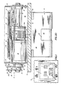
- Fig. 1 is a fragmentary diagrammatic view of an apparatus for dispensing paper notes according to one embodiment of the present invention installed in a wall
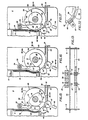
- Fig. 2 is a top plan view of the apparatus of the invention removed from its housing;
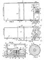
- Fig. 3 is a side elevation of the parts of the apparatus shown in Fig. 2;
- Fig. 4 is a front end elevation view of the apparatus looking in the direction of the arrows 4-4, Fig. 3;
- Fig. 5 is an enlarged sectional view with parts broken away looking in the direction of the arrows 5-5, Fig. 2;
- Fig. 6 is a sectional view looking in the direction of the arrows 6-6, Fig. 2;
- Fig. 7 is a detached perspective view of the feed roller for the picker mechanism;
- Fig. 8 is a detached perspective view of the note stack biasing lever which may be associated with the feed roller of Fig. 7;
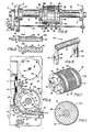
- Fig. 9 is a fragmentary sectional view of the friction rubber segment portion of the feed roller looking in the direction of the arrows 9-9, Fig. 5;
- Fig. 10 is a fragmentary sectional view looking in the direction of the arrows 10-10), Fig. 5;
- Fig. 11 is a sectional view of the feed roller taken on the line 11-11, Fig. 9, showing the feed roller construction between spaced portions of the friction rubber feed roller segment;
- Fig. 12 is a fragmentary view looking in the direction of the arrows 12-12, Fig. 5 illustrating the relationship between the feed and counter-rotating rollers;
- Fig. 13 is a fragmentary view similar to Fig. 12 looking in the direction of the arrows 13-13, Fig. 5, illustrating the thickness gauging and doubles detecting sensor devices forming a part of the apparatus;
- Fig. 14 is an enlarged view with parts broken away, similar to Fig. 4, illustrating the picker feed roller in the "home" position of Figs. 11 and 15 ready to commence a picking operation cycle;
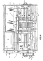
- Fig. 15 is a diagrammatic view similar to portions of Fig. 5 showing the feed roller in "home" position ready to start a picking operation cycle;
- Fig. 16 is a view similar to Fig. 15 with the feed roller rotated through an intial cycle portion to a position ready for its rubber friction segment to engage the note at the one end of the note supply stack which is held out of engagement with the rubber friction segment by the lever means;
- Fig. 17 is a view similar to Fig. 16 illustating lever means disengaged from the note supply stack, enabling the feed roller friction segment to engage and transfer the end note from the note supply stack along the path in the first direction;
- Fig. 18 is a view similar to Figs. 15 through 17 showing a further stage in the feeding cycle with the friction segment transferring the note past a counter-rotating roller and doubles detect roller toward a dispense channel communicating through an ATM housing wall to a customer delivery station;
- Fig. 19 is a view similar to Fig. 18 showing the final cycle stage of discharging a note to the ATM customer delivery station;
- Fig. 20 is an enlarged fragmentary top plan view of the dispense end of the mechanism shown in Fig. 2, installed in an ATM as shown in Figs. 1 and 19; and
- Figs. 20 and 21 are diagrammatic views showing slightly modified form of construction of the lever means and separator means.
- Similar numerals refer to similar parts throughout the various figures of the drawings.
- The fascia of an apparatus for dispensing paper notes, which is in this example an automated paper note teller or dispenser machine is diagrammatically indicated at 1 in Fig. 1 installed in a
wall 2 of a building such as a bank or a remote banking structure. A customer note delivery station for the mechanism is indicated generally at 4 in Figs. 1 and 18 to 20. - The ATM may have a keyboard 5 for actuating the cash dispenser, a slot 6 for receiving a customer's actuating and identification card, and a receipt-issuing slot 7, all of typical ATM cash dispenser construction, and these components may be mounted on the fascia 1.
- The
picker mechanism 3 of the invention preferably is located in the ATM in a compartment formed by spaced side walls 6 and a bottom wall 9 assembled and tied together by one or more cross members generally indicated at 10. - The paper currency or notes 11 to be dispensed are contained in a preferably metal note container generally indicated at 12. The
note container 12 may be a sealed container such as the container shown in United States Patent No. 4,113,140. In this type of container thenotes 11 are arranged in a stack 11a pressed toward anopening 13 through which the notes may be picked one at a time from the stack in the container. - The
note container 12 is assembled with and installed in the machine by sliding the container end having the opening 13 from left to right (Figs. 2 and 3) into the picker mechanism compartment along the bottom wall 9 to the position generally illustrated in Figs. 2 and 3. It is preferred that thecontainer 12 should be oriented so that the stack 11A ofnotes 11 has the notes on edge in the container pressed against theopening 13 and with the length of the notes extending laterally or cross-wise viewing Fig. 4. In this manner thenotes 11 are positioned so that the widths of the notes'extend generally vertically viewing Fig. 5. - The machine has a main feed
roller drive shaft 14 journaled at its ends inbearings 15 mounted onside walls 8 within the compartment containing the picker mechanism. One end of the shaft 14 (the left end Fig. 14) preferably has drive pulleys 16 and 17 mounted thereon. Thepulley 16 is driven by abelt 18 engaged over and driven bypulley 19 on the extended end ofdrive shaft 20 ofdrive motor 21. Thedrive motor 21 is mounted bybolts 22 on the inside of left side wall 8 (Figs. 4 and 14). -
Pulley 17 drivesbelt 23 trained overpulley 24 mounted on a one-way clutch 24a on ashaft 25 which is connected through aspeed reducer 26 with and driving acounter rotating shaft 27 journaled at its ends inmechanism side walls 8.Speed reducer 26 preferably has a 4 to 8 to 1 typically 6 to 1 ratio betweenshafts - The feed roller generally indicated at 28 (Fig. 7) is fixed to main
feed roller shaft 14 within the compartment intermediate the ends of the shaft 14 (Fig. 14). Thefeed roller 28 has acontrol cam 29 mounted on one end thereof.Cam 29 has a segment orlobe 30 with a circular surface concentric with the axis of mainfeed roller shaft 14, and alobe 31 with a shape of varying radial location with respect to the axis ofshaft 14, the purpose of which is described below. - A
pivot shaft 32 also extends between and is journaled at its ends of theside walls 8adjacent feed roller 28 and the end ofcontainer 12, and above both thefeed roller 28 and the container opening 13 (Fig. 5). - A U-shaped lever 33 (Fig. 8) has its
tubular portion 34 pivotally mounted onpivot shaft 32 with itslegs 35 straddling the ends offeed roller 28. Eachleg 35 oflever 33 has a preferablyflat edge 36 and an oppositecurved edge 37. Theflat edge 36 of one of thelegs 35 biased byspring 38 engages thefeed roller cam 29. - When the
cam segment 30 is engaged with the legflat edge 36, as shown in Fig. 5, thecurved leg edge 37 extends throughcontainer opening 13 and pushes the note stack 11A against note stack pressure, and holds thenotes 11 out of contact with thefeed roller 28 as shown in Fig. 5. The at rest or "home" positon of thefeed roller 29 is illustrated in Fig. 5. - The
feed roller 28 when rotating during a picking cycle of one revolution from and back to "home" position in a counter-clockwise direction (Fig. 5) similarly rotatescontrol cam 29, and theleg 35 initially engages thecam lobe 30 andcurved leg edge 37 holds thenotes 11 out of contact with thefeed roller 28. As rotation proceeds andlever leg 35 comes in contact withcam lobe 31, thelever 33, biased byspring 38, releases the note stack 11A enabling the end note to contact thefeed roller 28 of the stack 11A and note from the stack to be picked in the manner described in more detail below, during the extent of contact of thelever leg 37 with thecam lobe 31. As the picking cycle of one revolution of the feed roller and cam approaches termination, thecam segment 30 contacts the lever and moves the levercurved leg portion 37 toward the stack to again hold the stack 11A out of contact with thefeed roller 28. - Referring to Figs. 8 to 12,
feed roller 28 has a smooth circular or cylindrical outer surface comprising a central extended circular orarcuate area portion 39 and narrow circular or arcuatearea end portions 40 with flat circular recessedgrooves 41 formed in the roller between thecentral area 39 and end area portions 40 (Figs 7, 10 and 11). The outer smooth circular feed roller areas orzones friction material segments - The counter-rotating shaft 27 (Figs. 5, 12 and 14) has a pair of
counter-rotating separator rollers 44 mounted thereon in spaced relation at locations opposite the flatfeed roller grooves 41 so that the therollers 44 intermesh with but do not contact thefeed roller 28 as clearly illustrated in Fig. 12 which is a sectional view taken on a plane, as indicated in Fig. 5, passing through the axes ofshafts feed roller 28 andcounter-rotating rollers 44 is described more in detail below. Therollers 44, which are narrower in width than the flatfeed roller grooves 41, have an outer friction rubbermaterial circumferential surface 45. - The automated paper note teller or dispenser machine of the invention also has combined therein a simplified construction for detecting the presence of doubles that may be picked.
- Although the machine is designed in normal operation to separate notes in the stack 11A beneath the end note and to pick and discharge only the end note, nevertheless, for any one of a number of reasons, one or more notes may stick or otherwise adhere to the end note when being picked. This accounts for the inclusion of doubles detection means as a cooperative and interrelated part of the machine.
- A
thickness gauging shaft 46 for this purpose is mounted at its ends on side walls 8 (Figs. 13 and 14) close to and spaced counterclockwise from the counter-rotating shaft 27 (Fig. 5). A pair of notethickness gauging rollers 47 are mounted onshaft 46 in spaced relation at locations also opposite the flatfeed roller grooves 41 so that the gaugingrollers 47 have roller contact with the flatfeed roller grooves 41 as shown in Fig. 13. - The gauging
shaft 46, as shown, has a small diameter in cross section as compared with the very large cross-sectional diameter of the feed roller shaft 14 (Fig. 14). This permits note thickness gauging procedure to be carried out in accordance with procedures shown particularly in Figs. 7 and 8 of, and described in United States Patent No. 4,154,437. - When the machine is assembled, the
shaft 46 has an initial bend formed therein between its end supports; with the gaugingrollers 47 riding in and pressed by the bend against thefeed roller grooves 41. - Thus, as a note is picked and is fed between
feed rollers 28 and gaugingroller 47 as illustrated in Fig. 19,shaft 46 is deflected to increase the bend therein in accordance with the note thickness. Such shaft bend is increased if a doubles is picked and passed betweenrollers - This shaft deflection occurring during the thickness gauging operations described may be sensed by proximity sensor means 48 mounted on a
bar 49 extending betweenside walls 8. - The
proximity sensors 48 of known construction may have four states, stages, phases or modes. The first mode being that when thefeed roller 28 is located at home position as shown in Fig. 5. At this time at least one of the gaugingrollers 47 contacts a notch 50 (Fig. 11) in the feed roller and provides minimum bending to the gaugingshaft 46. This is the sensor "at home" mode. - The second mode is determined by the increased bend in
shaft 46, when therollers 47 ride in thefeed roller grooves 41 with no notes being gauged. This is referred to as the "no-note" mode. - When a single note is being picked normally and passes between the
rollers shaft 46 is increased from that of the "no-note" mode, and this increase is sensed bysensors 48 and may be referred to as a "single note" mode, the third of the four modes sensed. - When a double or even more than two notes are passed between
rollers shaft 46 will be bent or deflected even further. Such increased bend is sensed bysensors 48 as a fourth mode which may be referred to as a "multiple note" mode. - In this manner, the
sensors 48 not only sense no-notes, a single note, and more than one note or a doubles; but also sense when thefeed roller 28 is in home position, that is, at the beginning of one cycle of operation occurring during one revolution of thefeed roller 28. Thus, the sensors act as cycle sensors in addition to acting as doubles detect sensors. - Notes as they are picked, normally one note per cycle, are discharged or ejected rapidly by the feed roller into a
delivery slot 51 preferably formed between top andbottom plates feed roller 28 and beyond the gauging rollers 47 (Figs. 5 and 15-19). Thedelivery slot 51 may terminate at anopening 54 in thebuilding wall 2 or fascia 1 communicating with thecustomer delivery station 4. - The customer delivery station may have an angled trough-
like bottom wall 55 covered by a hingedlid 56. Thelid 56 may have a central cut outportion 57 for ease in grasping dispensed notes from the trough-like bottom wall while only slightly opening thelid 56 and also for visibility of notes that have been dispensed. - The rapid rotation of the
feed roller 28 in normally picking and dispensing notes imparts a high velocity to the dispensed notes sufficient to deliver the notes through thedelivery slot 51 and into the angled trough-like member 55 of thedelivery station 4. The delivery slot surfaces ofplates delivery slot plate 53 if desired. - The
drive motor 21 for the machine is a reversing motor and preferably may be a Stepper Motor product of Bodine Electric Company of 2500 W. Bradley Place, Chicago, Illinois 60618, Catalog ST-1, Type 23T Motor. Stepper Motors are controlled by programming which instructs the motor how many steps to move, by voltage impulses, plus or minus, forward or backward. - The length of movement of a step may be fixed for a particular motor. For example, such stepper motor used as a
drive motor 21 for the machine of the invention may have a step movement of three degrees rotation of thefeed roller 28 per step, so that themotor 21 delivers 120 steps in a picking cycle of feed roller operation. Such one revolution picking cycle of the mechanism picks and delivers one note per cycle. - In usual operation of an ATM cash dispenser, the customer may call for say ten notes of the particular denomination stacked in a note container. Accordingly, when the ATM is actuated, the
stepper motor 21 is instructed to drive thefeed roller 28 for ten cycles thus delivering ten notes, one per cycle of operation. - Details of a picking cycle of operation are illustrated diagrammatically in Figs. 15 through 19.
- A picking cycle starts with the
feed roller 28 at the "home" position described, such as shown in Figs. 6, 11 and 15 with the leadingedge 58 of therubber friction segment 42 offeed roller 28 at rest andmotor 21 is energized. - Figs. 15 through 19 diagrammatically illustrate certain features of the machine; for example, the
friction segment 42 is illustrated by an arcuate line in each of the views slightly greater in diameter than the circular line defining the smooth circularouter surface portion 39 of the feed roller. - The leading
edge 58 of the friction surface is indicated by a shoulder betweenarcuate line 42 and smoothcircular surface 39; and similarly the trailing edge ofarcuate segment 42 is indicated by ashoulder 59. - Further, the reference to the arcuate rubber
friction material segment 42, collectively includes thenarrow segment portions 42a, and themain friction segment 42 which is centrally located between theflat grooves 41. Thenarrow segment portions 42a are located outside of saidgroove 41 and are interrupted fromcentral portion 42 by said grooves. - This relationship provides a total axial length of the feed roller
friction surface portions grooves 41 which, in effect, is twice the width of one of the grooves. - Also, in Figs. 15 through 19 the
counter-rotating roller 44 and the gaugingroller 47 each are shown by circles slightly intersecting thecircular portion 39 which defines the smooth outer surface of thefeed roller 28 because of the relative locations of the indicated components as illustrated in Figs. 12 and 13. In Fig. 12, thecounter-rotating rollers 44 are intermeshed with thegrooves 41 infeed roller 28 but do not contact the feed roller. In Fig. 13. the gaugingrollers 47 are shown in rolling engagement with the flat recessed surfaces ofgrooves 41 in order to perform the gauging and doubles detect functions described. - Returning now to Fig. 15 and to the "home" position of the parts illustrated, at the time when the
drive motor 21 is energized, thecurved edge 37 oflever 33 is holding the note stack 11A out of contact with thesmooth portion 39 of the feed roller. This relationship continues as the feed roller rotates counterclockwise to the position shown in Fig. 16. - Meanwhile, the circumferential friction surface of the
counter-rotating rollers 44 are intermeshed with but out of contact with thefeed roller grooves 41. - When the parts reach the positions shown in Fig. 16, the leading
edge 58 of the feedroller friction segment 42 arrives generally opposite the location of the lower edges of the notes in stack 11A and approaches intermeshing status of friction surface of feed roller and the friction surface of thecounter-rotating rollers 44. - As the feed roller continues to rotate to the position of Fig. 17, the
cam lobe 31releases lever 33 and the feedroller friction segment 42 engages the end note of the stack 11A and by frictional engagement pulls that note from the stack as indicated by the heavy line displayed note 11 B in Fig. 17. - Continued rotation of the
feed roller 28 drives the note 11B past thecounter-rotating roller 44 and past the doubles detect gaugingroller 47 as shown in Fig. 18. - As the feed roller continues rotation from the position of Fig. 18 to that of Fig. 19, the picked note 11B is discharged and the
lever 33 is then moved bycam lobe 30 to hold the stack 11A out of contact with the feed roller. The feed roller then completes its cycle of operation and returns from the position of Fig. 19 to that of Fig. 15, having picked one note. - The construction of the picker mechanism is intended to avoid picking more than one note from the stack 11A at a time. This is accomplished normally by the cooperative action of the
counter-rotating roller 44. If during a picking cycle one or more notes next underneath the end note of the stack commence to emerge from the stack as a note 11 B is being picked as described, the circumferential friction surfaces of the intermeshedcounter-rotating rollers 44 engage the note or notes trying to emerge between the note being picked and move such additional notes back into the stack. - The action of the
counter-rotating rollers 44, however, is not sufficient to impede or prevent the frictional segment engaged end note of the stack from being picked. - The condition producing this result is that the friction-engaging force of the feed
roller friction segment 42 exerted on the outer surface of the stack end note is greatly in excess of that of therollers 44 on the note inner surface. First of all, the zone of contact of thesegment 42 with the note outer surface, as described above, has a greater length than the frictional surface zone of contact of the two narrow widthcounter-rotating rollers 44. Whether these zones of contact with the note by frictional areas of therollers - Increasing the effect of such feed roller friction force is the larger diameter of the
friction roller 28 as compared with that of thecounter-rotating rollers 44, plus the fact that the speed of rotation of thefeed roller 28 is considerably greater than that of thecounter-rotating rollers 44. - Further, the note 11 B being picked is driven between the
feed roller 28 and the notethickness gauging rollers 47 and is pinched between said rollers which aids in continuing to drive the note in note feeding direction, irrespective of any resistance at the trailing portion of the note exerted by the friction separator means, that is, thecounter-rotating rollers 44. - These characteristics normally enable one note to be picked at a time for each cycle of note- picking operation and when a number of notes are to be picked in succession, the spacing between successive notes is automatically maintained the same so that the notes are discharged at a uniform rate into the
customer delivery station 4. - The operation of the machine described below results if some abnormal condition is detected by movement of a note thickness gauging roller away from the feed roller indicating that more than one note thickness had been found. The abnormal condition may be one of numerous kinds, such as the known tendency of notes in a stack of new notes to stick together, or such as the actual presence of adhesion between two notes due to the accidental presence of a sticky substance transferred to a note by a previous note handler, or such as a portion of one note being folded about the end of another note.
- When such increased note thickness is gauged by actuation of the
thickness gauging rollers 47, thesensors 48 through typical control circuitry of known types used in ATMs which may include a programmed microprocessor, transmit a signal to the stepper motor directing it to stop and reverse its drive movement for the same number of steps that have been fed to thefeed roller 28 in its forward motion. This drives the note or notes whose thickness has been gauged, in a reverse direction back into the stack by the reverse action of the feedroller friction segment 42. - As the drive is reversed to enable the
feed roller 28 to drive the abnormal thickness note collection back into the stack, thecounter-rotating rollers 44 are not reversed due to the action of the one-way clutch 24a present in the drive system for theshaft 27 on which thecounter-rotating rollers 44 are mounted (Figs. 12 and 14). - In other words,
pulley 24 is mounted on the one-way clutch 24a in turn mounted onshaft 27, so that whenfeed roller 28 is driven in note feeding direction,counter-rotating rollers 44 are driven in a reverse direction. However, when the . drive for thefeed roller 28 is reversed, the one-way clutch 24a over-runs, and therollers 44 are not driven in a reverse direction. - After the
stepper motor 21 has reversely driven thefeed roller 28 for the same number of steps that the feed roller had been advanced, the stepper motor stops and automatically again reverses to normal forward driving of the feed roller. Ordinarily the drive motor reversal described corrects the abnormal condition and feeds a single note. If such normal feeding does not occur during the first drive motor reversal, the reversals are repeated until the abnormal thickness condition disappears and separation of notes and normal feeding and picking thereof is reestablished. - Such repeated reversals of feed roller movement to correct an abornamal thickness condition involves back and forward note scrubbing of the abnormal thickness notes between the
friction segment 42 and the friction separator devices orrollers 44. This repeated back and forward movement, of course, is a result of the repeated reversed movement of thefeed roller 28. - This cooperative and coordinated relationship between the simple reversing motor drive, the feed roller with a friction segment, the counter-rotating friction rollers, and the thickness gauging rollers, provide a new and unique result. This result eliminates problems heretofore present in ATMs relating to the manner in which doubles are detected, handled, transported and stored. Thus the machine eliminates doubles diversion and transporting doubles to a divert container, and also eliminates a divert container and its protective measures.
- In the unusual circumstance that the back-and- forth movement of detected doubles to and from the stack fails to separate the notes involved and fails to establish normal picking operation of notes, one at a time, from the stack, after a predetermined series of reverse operations the number of which may be programmed into the mechanism control, the abnormal thickness note group may be fed to the
customer discharge station 4, and the note status recorded. - The simplified construction and operation of the automated paper note teller or dispenser machine of the invention permits convenient location of the mechanism adjacent an end of a container for the supply stack of notes to be picked, and adjacent an ATM fascia so that no transport mechanism is required for delivery of the picked notes one at a time to the customer delivery station.
- However, this beneficial result does not preclude the new machine of the invention from being used in ATM constructions where some means of conveying dispensed notes may be desired to present the notes at a location remote from the picker, for example, for conveying the notes with other denomination notes picked from other supply stacks.
- Although the preferred form of note separator means shown and described comprise counter-rotating friction-surfaced
rollers 44,rubber pads 66 may perform the same separating functions when located on pad holders 67 fixed at the position occupied byrollers 44 with such pads directed toward and intermeshed into thefeed roller grooves 41 so as to provide frictional resistance directed toward the inside of the end note being picked. Such pads, likerollers 44 have frictional resistance of a smaller magnitude of frictional force applied toward the inside of the end note being picked by the feedroller friction segment 42, than the segment frictional picking force, (Fig. 22). - Another preferred characteristic of the machine is that the arcuate length of the rubber friction material segment of the feed roller is approximately equal to the note width. This is desirable in positioning the components of the cash dispenser in an ATM from the standpoint of minimizing the required vertical dimension of the housing compartment of the ATM to give flexibility in locating at a most convenient position, the customer delivery station.
- The manner in which the rubber friction
material segment portions feed roller 28 in retaininggrooves 43 is desirable in order to permit simple replacement or renewal of the rubber when it becomes worn. - A slightly modified construction is illustrated in Fig. 21 wherein the stack hold-
back lever 60 normally is located in holding position shown by alever arm 61 projecting upward from thelever pivot axis 62 for engagement with anarmature 63 of a solenoid 64. - Such construction may be used with a drive motor which continuously rotates the feed roller shaft 65. Normally the
solenoid armature 63 holds thelever 60 in the position shown, to which the lever is moved in normal operation by thecam 66. When the machine is directed to dispense one or more notes, thesolenoid armature 63 is withdrawn permitting the friction picker to operate in the manner described and to pick the number of notes called for. The drive motor for the optional continuous rotation of the feed roller may be either a stepper motor as described, or a typical reversing motor. - The feed roller element having the described construction with grooves and friction material segments is preferably made either of metal or of plastic material.
- The rubber used for the feed roller rubber friction material segments, and for the surface of the counter-rotating roller, preferably is urethane rubber.
- The
proximity sensors 48 preferably are a product of Electro Corporation, P.O. Box 3049, 1845-57th, Sarasota, Florida 33578, Type No. PA-12D-43. - The machine has been described as including the use of the lever 33 (Fig. 8) or lever 60 (Fig. 21) to hold back the stack notes from contact with the
feed roller 28 except when thefriction segment 42 is actually engaged with and picking a note. - This arrangement is preferred where the stack of notes contains a random arrangement of new and old notes or all old notes. When the stack of notes contains only new notes, the lever hold-back arrangement may be omitted.
- The hold-back system avoids possible limp, worn note pile-up from note contact under pressure with the smooth feed roller surface portion during rapid one note per cycle picking operations. When only new notes are involved the smooth feed roller surface portion easily slips over new note surfaces.
- Accordingly, the machine construction and operation satisfy the stated objectives; avoid problems that have arisen in the past with prior art machines of either the friction or suction types; enables notes to be picked one at a time and the handling of doubles to be eliminated since doubles are returned to the stack in normal machine operation; provides a low-cost picker mechanism construction which has low maintenance costs; and thereby satisfy needs existing in the field of ATMs.
- In the foregoing description, certain terms have been used for brevity, clearness and understanding but no unnecessary limitation are to be implied therefrom beyond the requirements of the prior art because such terms are used for descriptive purposes and are intended to be broadly construed.
- Moreover, the description and illustration of the invention is by way of example, and the scope of the invention is not limited to the exact details shown or described.
Claims (19)
Applications Claiming Priority (2)
| Application Number | Priority Date | Filing Date | Title |
|---|---|---|---|
| US06/510,410 US4494747A (en) | 1983-07-01 | 1983-07-01 | Paper currency dispenser friction picker mechanism |
| US510410 | 1983-07-01 |
Publications (3)
| Publication Number | Publication Date |
|---|---|
| EP0148877A1 EP0148877A1 (en) | 1985-07-24 |
| EP0148877A4 EP0148877A4 (en) | 1985-10-28 |
| EP0148877B1 true EP0148877B1 (en) | 1988-08-17 |
Family
ID=24030620
Family Applications (1)
| Application Number | Title | Priority Date | Filing Date |
|---|---|---|---|
| EP84902490A Expired EP0148877B1 (en) | 1983-07-01 | 1984-06-13 | Paper currency dispenser apparatus |
Country Status (8)
| Country | Link |
|---|---|
| US (1) | US4494747A (en) |
| EP (1) | EP0148877B1 (en) |
| JP (2) | JPH0742011B2 (en) |
| AU (1) | AU559100B2 (en) |
| CA (1) | CA1228875A (en) |
| DE (1) | DE3473433D1 (en) |
| IT (2) | IT8453592V0 (en) |
| WO (1) | WO1985000348A1 (en) |
Families Citing this family (62)
| Publication number | Priority date | Publication date | Assignee | Title |
|---|---|---|---|---|
| US4660822A (en) * | 1985-02-07 | 1987-04-28 | Brandt, Inc. | Compact apparatus for dispensing a preselected mix of paper currency or the like |
| US4715597A (en) * | 1985-03-19 | 1987-12-29 | Ricoh Company, Ltd. | Automatic document feeder |
| DE3650595T2 (en) * | 1985-06-27 | 1997-05-22 | Interbold | Document delivery device |
| US4871085A (en) * | 1985-06-27 | 1989-10-03 | Diebold Incorporated | Apparatus for identifying and indicating the content of document canisters |
| US5141127A (en) * | 1985-06-27 | 1992-08-25 | Diebold, Incorporated | Method and apparatus for identifying and indicating the content of document canisters |
| US4664369A (en) * | 1985-10-01 | 1987-05-12 | Diebold Incorporated | Multiple sheet indicator apparatus and method |
| US4662536A (en) * | 1985-12-06 | 1987-05-05 | Powers Ernest G | Paper filter dispenser |
| DE3708601A1 (en) * | 1986-03-18 | 1987-10-01 | Canon Kk | Paper feed device for a recording apparatus |
| JP2596040B2 (en) * | 1988-02-13 | 1997-04-02 | オムロン株式会社 | Paper feeding device |
| JPH0726276Y2 (en) * | 1988-05-09 | 1995-06-14 | 旭精工株式会社 | Card dispenser for card vending machines |
| GB8907976D0 (en) * | 1989-04-08 | 1989-05-24 | Rawson L E J | Multi-grade sheet feeding system |
| GB2230760A (en) * | 1989-04-11 | 1990-10-31 | Ofrex Group Holdings Plc | Sheet feeding mechanism |
| US4916493A (en) * | 1989-08-24 | 1990-04-10 | Xerox Corporation | Exit roller reversal gate for duplex printing |
| ES2021913A6 (en) * | 1989-12-20 | 1991-11-16 | Univ Valencia | Machine for dispensing newspapers, magazines and/or similar objects. |
| US5244191A (en) * | 1991-07-08 | 1993-09-14 | Matsushita Electric Industrial Co., Ltd. | Sheet feeding apparatus for image recording system |
| US5373723A (en) * | 1992-09-11 | 1994-12-20 | Chou; Shou-Lai | Apparatus for determining friction between a support roller and a rubber roller |
| JP2531226Y2 (en) * | 1992-11-26 | 1997-04-02 | 喜和 石渡 | Banknote storage mechanism |
| JPH06206646A (en) * | 1993-01-11 | 1994-07-26 | Mita Ind Co Ltd | Paper feeder for image forming device |
| US5293818A (en) * | 1993-05-06 | 1994-03-15 | Mandzuk Raymond A | Transfer device, such as a printer device |
| US5622363A (en) * | 1994-11-23 | 1997-04-22 | Harris Corporation | Sheet feeder system and method |
| US5577720A (en) * | 1995-04-04 | 1996-11-26 | Interbold | Self-adjusting sensor |
| JPH0986705A (en) * | 1995-07-18 | 1997-03-31 | Mitsubishi Electric Corp | Automatic paper feeder |
| US6273413B1 (en) * | 1997-11-28 | 2001-08-14 | Diebold, Incorporated | Automated banking machine with sheet directing apparatus |
| US7584883B2 (en) * | 1996-11-15 | 2009-09-08 | Diebold, Incorporated | Check cashing automated banking machine |
| US7559460B2 (en) * | 1996-11-15 | 2009-07-14 | Diebold Incorporated | Automated banking machine |
| US7513417B2 (en) * | 1996-11-15 | 2009-04-07 | Diebold, Incorporated | Automated banking machine |
| US6164638A (en) * | 1997-11-28 | 2000-12-26 | Dicbold, Incorporates | Automated banking machine with currency recycling canisters |
| US6318714B1 (en) * | 1997-11-28 | 2001-11-20 | Diebold, Incorporated | Document unstack system for currency recycling automated banking machine |
| KR100366418B1 (en) * | 1999-11-22 | 2002-12-31 | 엘지엔시스(주) | cash dispenser |
| US6874778B2 (en) * | 2000-10-31 | 2005-04-05 | Canon Kabushiki Kaisha | Sheet feeding apparatus and image forming apparatus provided with same |
| US20050098622A1 (en) * | 2001-10-09 | 2005-05-12 | Gregory Jantsch | Dispensing of currency |
| US7387236B2 (en) * | 2001-10-09 | 2008-06-17 | Delaware Capital Formation, Inc. | Dispensing of currency |
| WO2004036386A2 (en) * | 2002-10-18 | 2004-04-29 | Diebold, Incorporated | Automated banking machine |
| US7140607B2 (en) * | 2002-10-18 | 2006-11-28 | Diebold Self-Service Systems Division Of Diebold, Incorporated | Cash dispensing automated banking machine with note unstacking and validation |
| ES2389561T3 (en) * | 2003-03-10 | 2012-10-29 | Diebold, Incorporated | Automatic banking machine dispensing cash and method |
| PL214866B1 (en) * | 2003-03-10 | 2013-09-30 | Diebold Inc | Cash dispensing automated banking machine deposit accepting system and method |
| DE10342568A1 (en) * | 2003-09-15 | 2005-04-14 | Giesecke & Devrient Gmbh | Device and method for separating sheet material |
| GB0427693D0 (en) * | 2004-12-17 | 2005-01-19 | Ncr Int Inc | An automated teller machine |
| CN101898693B (en) * | 2005-06-14 | 2014-03-26 | 光荣株式会社 | Paper conveying device |
| US7744082B2 (en) * | 2005-06-14 | 2010-06-29 | Glory Ltd. | Paper-sheet feeding device with kicker roller |
| US20070001378A1 (en) * | 2005-06-20 | 2007-01-04 | Gregory Jantsch | Dispensing of currency |
| US20070001383A1 (en) * | 2005-06-20 | 2007-01-04 | Gregory Jantsch | Dispensing of currency |
| CA2516555A1 (en) * | 2005-08-19 | 2007-02-19 | Cashcode Company Inc. | Banknote validator with banknote stack receiver |
| JP2007076842A (en) * | 2005-09-15 | 2007-03-29 | Brother Ind Ltd | Document holding tray, document conveyance device, and image reading device |
| JP2007131410A (en) * | 2005-11-10 | 2007-05-31 | Toshiba Corp | Paper sheet taking-out device |
| WO2007126878A2 (en) * | 2006-03-29 | 2007-11-08 | Talaris Inc. | Apparatus and method for adding note dispensing positions to a secure cash dispenser |
| JP5034514B2 (en) * | 2007-01-23 | 2012-09-26 | 富士電機リテイルシステムズ株式会社 | How to pay out vertically stored bills |
| EP2266448B1 (en) * | 2009-06-23 | 2017-01-18 | Hans Georg Hagleitner | Device for output of sections of paper strip |
| HUE028107T2 (en) * | 2011-07-13 | 2016-11-28 | Sca Hygiene Prod Ab | Dispenser and stack of sheet products |
| CN112386151A (en) | 2012-10-26 | 2021-02-23 | 易希提卫生与保健公司 | Dispenser |
| WO2014065731A1 (en) * | 2012-10-26 | 2014-05-01 | Sca Hygiene Products Ab | Separation unit and a dispenser comprising a separation unit |
| EP2911564B1 (en) | 2012-10-26 | 2020-01-22 | Essity Hygiene and Health Aktiebolag | Separation unit and a dispenser comprising a separation unit |
| US9990793B2 (en) * | 2013-07-31 | 2018-06-05 | Ncr Corporation | Media item separation |
| CN103708250B (en) | 2013-12-24 | 2016-01-20 | 广州广电运通金融电子股份有限公司 | A kind of separation device of sheet kind medium and financial self-service equipment |
| CN110742539B (en) | 2014-04-28 | 2022-07-26 | 易希提卫生与保健公司 | Dispenser |
| WO2016093535A1 (en) * | 2014-12-10 | 2016-06-16 | 엘지전자 주식회사 | Vehicle display device and vehicle comprising same |
| KR101924059B1 (en) * | 2015-09-01 | 2019-02-22 | 엘지전자 주식회사 | Display apparatus for vehicle and Vehicle including the same |
| ES2668940T3 (en) * | 2015-05-12 | 2018-05-23 | Tranzonic Companies | Paperless toilet seat dispensing device |
| US10167152B2 (en) * | 2016-06-30 | 2019-01-01 | Ncr Corporation | Folded media detection and processing |
| EP3485469B1 (en) * | 2016-07-13 | 2021-10-27 | Diebold Nixdorf, Incorporated | Contact stripper/feed wheel implementation |
| CN108502581B (en) * | 2018-03-23 | 2020-08-18 | 深圳怡化电脑股份有限公司 | Medium separation mechanism and self-service financial equipment |
| KR102093846B1 (en) * | 2020-02-27 | 2020-03-27 | (주)한틀시스템 | Cash dispense machine |
Family Cites Families (15)
| Publication number | Priority date | Publication date | Assignee | Title |
|---|---|---|---|---|
| US1174391A (en) * | 1915-07-28 | 1916-03-07 | Louis K Fisher | Separating means for sheet-feeding machines. |
| BE795343A (en) * | 1972-02-22 | 1973-05-29 | Pennsylvania Res Ass Inc | SHEET TRAINING, SEPARATION AND STACKING MACHINE |
| US3874650A (en) * | 1973-01-05 | 1975-04-01 | Monarch Marking Systems Inc | Record separating, reading, and delivering apparatus |
| JPS5211997B2 (en) * | 1973-05-10 | 1977-04-04 | ||
| US3970298A (en) * | 1975-06-05 | 1976-07-20 | Pitney-Bowes, Inc. | Mixed thickness sheet separator and feeder |
| DE2650564B1 (en) * | 1976-11-04 | 1978-02-16 | Nixdorf Comp Ag | Device for separating receipts, cards and the like, especially banknotes |
| JPS609898Y2 (en) * | 1976-12-10 | 1985-04-05 | ロ−レルバンクマシン株式会社 | Paper sheet feeding roller |
| US4159782A (en) * | 1977-05-02 | 1979-07-03 | Docutel Corporation | Banking machine control |
| US4154437A (en) * | 1977-07-15 | 1979-05-15 | Diebold, Incorporated | Multiple bill detector for currency dispensers |
| JPS5418797A (en) * | 1977-08-15 | 1979-02-13 | Ricoh Co Ltd | Card separating and feeding apparatus |
| JPS5751242Y2 (en) * | 1977-09-16 | 1982-11-09 | ||
| JPS5540505A (en) * | 1978-09-13 | 1980-03-22 | Tachikawa Spring Co | Waist bone supporting and controlling apparatus of seatback |
| US4232860A (en) * | 1978-10-20 | 1980-11-11 | Automecha Ltd. | Paper feeder |
| SE8003705L (en) * | 1980-05-19 | 1981-11-20 | Leif Lundblad | DEFINITION OF SECURITIES AND OTHER DOCUMENTS |
| US4355797A (en) * | 1980-10-06 | 1982-10-26 | Diebold Incorporated | Picker mechanism for automatic banking machines |
-
1983
- 1983-07-01 US US06/510,410 patent/US4494747A/en not_active Expired - Lifetime
-
1984
- 1984-06-13 WO PCT/US1984/000907 patent/WO1985000348A1/en active IP Right Grant
- 1984-06-13 DE DE8484902490T patent/DE3473433D1/en not_active Expired
- 1984-06-13 JP JP59502406A patent/JPH0742011B2/en not_active Expired - Lifetime
- 1984-06-13 EP EP84902490A patent/EP0148877B1/en not_active Expired
- 1984-06-13 AU AU30671/84A patent/AU559100B2/en not_active Expired
- 1984-06-21 CA CA000457160A patent/CA1228875A/en not_active Expired
- 1984-06-29 IT IT8453592U patent/IT8453592V0/en unknown
- 1984-06-29 IT IT67665/84A patent/IT1179722B/en active
-
1994
- 1994-10-18 JP JP6288531A patent/JP2535317B2/en not_active Expired - Lifetime
Also Published As
| Publication number | Publication date |
|---|---|
| JP2535317B2 (en) | 1996-09-18 |
| EP0148877A1 (en) | 1985-07-24 |
| JPH07251958A (en) | 1995-10-03 |
| JPH0742011B2 (en) | 1995-05-10 |
| AU559100B2 (en) | 1987-02-19 |
| DE3473433D1 (en) | 1988-09-22 |
| IT8467665A1 (en) | 1985-12-29 |
| US4494747A (en) | 1985-01-22 |
| CA1228875A (en) | 1987-11-03 |
| IT1179722B (en) | 1987-09-16 |
| IT8467665A0 (en) | 1984-06-29 |
| JPS60501755A (en) | 1985-10-17 |
| EP0148877A4 (en) | 1985-10-28 |
| AU3067184A (en) | 1985-02-07 |
| IT8453592V0 (en) | 1984-06-29 |
| WO1985000348A1 (en) | 1985-01-31 |
Similar Documents
| Publication | Publication Date | Title |
|---|---|---|
| EP0148877B1 (en) | Paper currency dispenser apparatus | |
| EP0616963B1 (en) | Sheet handling apparatus | |
| EP0174200B1 (en) | Sheet dispensing method and apparatus | |
| US4095781A (en) | Currency dispensing apparatus | |
| EP0793199A2 (en) | Bill handling machine | |
| JPH0236977B2 (en) | ||
| JPH0198553A (en) | Sheet treater | |
| EP0132329B1 (en) | Sheet feeding apparatus | |
| JPS5934908Y2 (en) | Collector | |
| CA2065484A1 (en) | Apparatus for receiving and issuing sheets | |
| EP0151808B1 (en) | Improved currency-dispensing method and apparatus | |
| US20210174628A1 (en) | A device, an apparatus and a method for directing bank notes | |
| JPS6112535A (en) | Sheet feeder | |
| JP2502855Y2 (en) | Recycling banknote processing machine | |
| JP7169627B2 (en) | banknote recycle device | |
| GB2111951A (en) | Sheet delivery mechanisms | |
| JPS5819645Y2 (en) | Banknote reject device | |
| JPH0540048Y2 (en) | ||
| JPH0439246A (en) | Cash dispenser | |
| JPH0213418Y2 (en) | ||
| JPH11353532A (en) | Discharge device for thin body such as paper money | |
| JPH04197943A (en) | Pay-out delivery control device in bill pay-in/out machine | |
| JPH0825683B2 (en) | Paper delivery device | |
| KR910007608Y1 (en) | Distributor | |
| WO2002046074A1 (en) | Document supply apparatus |
Legal Events
| Date | Code | Title | Description |
|---|---|---|---|
| PUAI | Public reference made under article 153(3) epc to a published international application that has entered the european phase |
Free format text: ORIGINAL CODE: 0009012 |
|
| 17P | Request for examination filed |
Effective date: 19850220 |
|
| AK | Designated contracting states |
Designated state(s): BE CH DE FR GB LI NL SE |
|
| 17Q | First examination report despatched |
Effective date: 19861014 |
|
| D17Q | First examination report despatched (deleted) | ||
| GRAA | (expected) grant |
Free format text: ORIGINAL CODE: 0009210 |
|
| AK | Designated contracting states |
Kind code of ref document: B1 Designated state(s): BE CH DE FR GB LI NL SE |
|
| REF | Corresponds to: |
Ref document number: 3473433 Country of ref document: DE Date of ref document: 19880922 |
|
| ET | Fr: translation filed | ||
| PLBE | No opposition filed within time limit |
Free format text: ORIGINAL CODE: 0009261 |
|
| STAA | Information on the status of an ep patent application or granted ep patent |
Free format text: STATUS: NO OPPOSITION FILED WITHIN TIME LIMIT |
|
| 26N | No opposition filed | ||
| EAL | Se: european patent in force in sweden |
Ref document number: 84902490.6 |
|
| NLS | Nl: assignments of ep-patents |
Owner name: INTERBOLD |
|
| REG | Reference to a national code |
Ref country code: GB Ref legal event code: IF02 |
|
| PGFP | Annual fee paid to national office [announced via postgrant information from national office to epo] |
Ref country code: FR Payment date: 20030512 Year of fee payment: 20 |
|
| PGFP | Annual fee paid to national office [announced via postgrant information from national office to epo] |
Ref country code: GB Payment date: 20030516 Year of fee payment: 20 |
|
| PGFP | Annual fee paid to national office [announced via postgrant information from national office to epo] |
Ref country code: CH Payment date: 20030519 Year of fee payment: 20 |
|
| PGFP | Annual fee paid to national office [announced via postgrant information from national office to epo] |
Ref country code: NL Payment date: 20030522 Year of fee payment: 20 |
|
| PGFP | Annual fee paid to national office [announced via postgrant information from national office to epo] |
Ref country code: SE Payment date: 20030527 Year of fee payment: 20 Ref country code: DE Payment date: 20030527 Year of fee payment: 20 |
|
| PGFP | Annual fee paid to national office [announced via postgrant information from national office to epo] |
Ref country code: BE Payment date: 20030528 Year of fee payment: 20 |
|
| PG25 | Lapsed in a contracting state [announced via postgrant information from national office to epo] |
Ref country code: LI Free format text: LAPSE BECAUSE OF EXPIRATION OF PROTECTION Effective date: 20040612 Ref country code: GB Free format text: LAPSE BECAUSE OF EXPIRATION OF PROTECTION Effective date: 20040612 Ref country code: CH Free format text: LAPSE BECAUSE OF EXPIRATION OF PROTECTION Effective date: 20040612 |
|
| PG25 | Lapsed in a contracting state [announced via postgrant information from national office to epo] |
Ref country code: NL Free format text: LAPSE BECAUSE OF EXPIRATION OF PROTECTION Effective date: 20040613 |
|
| BE20 | Be: patent expired |
Owner name: *DIEBOLD INC. Effective date: 20040613 |
|
| REG | Reference to a national code |
Ref country code: GB Ref legal event code: PE20 |
|
| REG | Reference to a national code |
Ref country code: CH Ref legal event code: PL |
|
| NLV7 | Nl: ceased due to reaching the maximum lifetime of a patent |
Effective date: 20040613 |
|
| EUG | Se: european patent has lapsed |