EP0148550B1 - Method and apparatus for thruster transient control - Google Patents
Method and apparatus for thruster transient control Download PDFInfo
- Publication number
- EP0148550B1 EP0148550B1 EP84302734A EP84302734A EP0148550B1 EP 0148550 B1 EP0148550 B1 EP 0148550B1 EP 84302734 A EP84302734 A EP 84302734A EP 84302734 A EP84302734 A EP 84302734A EP 0148550 B1 EP0148550 B1 EP 0148550B1
- Authority
- EP
- European Patent Office
- Prior art keywords
- thruster
- axis
- disturbance torque
- maneuver
- spacecraft
- Prior art date
- Legal status (The legal status is an assumption and is not a legal conclusion. Google has not performed a legal analysis and makes no representation as to the accuracy of the status listed.)
- Expired - Lifetime
Links
Images


Classifications
-
- B—PERFORMING OPERATIONS; TRANSPORTING
- B64—AIRCRAFT; AVIATION; COSMONAUTICS
- B64G—COSMONAUTICS; VEHICLES OR EQUIPMENT THEREFOR
- B64G1/00—Cosmonautic vehicles
- B64G1/22—Parts of, or equipment specially adapted for fitting in or to, cosmonautic vehicles
- B64G1/24—Guiding or controlling apparatus, e.g. for attitude control
- B64G1/26—Guiding or controlling apparatus, e.g. for attitude control using jets
-
- B—PERFORMING OPERATIONS; TRANSPORTING
- B64—AIRCRAFT; AVIATION; COSMONAUTICS
- B64G—COSMONAUTICS; VEHICLES OR EQUIPMENT THEREFOR
- B64G1/00—Cosmonautic vehicles
- B64G1/22—Parts of, or equipment specially adapted for fitting in or to, cosmonautic vehicles
- B64G1/24—Guiding or controlling apparatus, e.g. for attitude control
- B64G1/244—Spacecraft control systems
Definitions
- This invention relates to method and apparatus for spacecraft attitude control, and particularly to satellite transient attitude steady state attitude control during transfer orbit, stationkeeping, synchronous orbit and in general during any change in orbit velocity maneuver.
- the invention relates to thruster prebias control in order to compensate for imbalance and cross couplings due to misalignment among a plurality of attitude control thrusters of a spacecraft, such as a synchronous satellite during orbit adjustment.
- Spacecraft particularly satellites designed for geosynchronous orbit and having large structural arrays of solar panels, are particularly susceptible to structural oscillation due to the transient disturbances induced by small rocket engines known as thrusters.
- the transient disturbances cause not only structural oscillations but can cause undesirable changes in spacecraft attitude which affect antenna direction and, therefore, signal target and signal strength.
- the problem of spacecraft dynamics and disturbance torque is particularly acute during the orbit adjustment in the stationkeeping mode wherein the satellite attitude is controlled exclusively by gas thrusters.
- EP-A-0101302 relates to an apparatus for controlling the attitude of a spacecraft with respect to each of three orthogonal axes, comprising means for imparting angular velocity to the spacecraft about each of the axes, means for measuring the angular deviation of the spacecraft with respect to a desired orientation of the spacecraft with respect to each of the axes and for measuring the angular velocity of the spacecraft about each of the axes.
- the apparatus further comprises means for periodically observing the output signal produced by the measuring means and creating in response thereto a pulse train signature for each axis tailored to maneuver the spacecraft towards its desired orientation with respect to that axis and means responsive to each pulse train signature for loading into a shift register and piecewise outputting therefrom signals for alternately switching on and off associated imparting means in accordance with the pulse train signature.
- a method for use in a spacecraft to counteract disturbance transients during a change in velocity maneuver employing a plurality of thrusters, at least a first thruster and a second thruster being disposed to develop mutually counteractive moment arms of thrust relative to at least one axis through a center of mass of the spacecraft, said first thruster and said second thruster being capable of developing unequal moment arms of force, the method comprising the steps of storing prior to said manuever a value representative of an estimated disturbance torque thereafter modulating in response to said stored value one of said first and second thrusters during said maneuver to counteract an actual disturbance torque a sufficient amount to compensate for said actual disturbance torque in order to minimize a net position error without initially detecting said net position error, detecting said net position error, said net position error being indicative of a difference between said estimated disturbance torque and said actual disturbance torque with respect to said axis and thereafter modulating in response to a sum of said stored value and said net position error one of said first and second
- an apparatus for use in a spacecraft for independently modulating thruster discharge to counteract disturbance transients during a change in velocity maneuver comprising a plurality of thrusters, at least a first thruster and a second thruster being disposed to develop mutually counteractive moment arms of thrust relative to at least one axis through a center of mass of said spacecraft, said first thruster and said second thruster being capable of developing unequal thrust, the appartus comprising means arranged to generate a value representative of an estimated net disturbance torque for storage prior to said maneuver, means arranged to modulate one of said first and second thrusters in response to said estimated disturbance torque value obtained following storage during said maneuver to counteract an actual disturbance torque a sufficient amount to compensate for said actual disturbance torque in order to minimize net position error without initially detecting said net position error, means for detecting said net position error, said net position error being indicative of a difference between said estimated disturbance torque and said actual disturbance torque with respect to said one axis, and means for combining said net position
- the invention has particular advantages in that the feedback loop of the servo control system need have only relatively low gain while still accurately controlling spacecraft attitude. Moreover, low gain permits a relatively low control bandwidth which is not sensitive to loop time delay, to sensor phase lag, to nonlinearity of the pulse-width/pulse-frequency thrust system or to parameter uncertainty.
- a complex leadlag network with relatively long delay is included in the position control loop of a servo control system and a high pass function is included in the rate loop of the servo control system to provide damping of the control loop during a change in velocity maneuver.
- FIG. 1 illustrates the features of a typical spacecraft 10, such as a geosynchronous satellite having solar panels 12 and 14 disposed along the pitch axis 6.
- geosynchronous satellites are disposed with the pitch axis 6 aligned with the North-South axis of the earth.
- the yaw axis ljJ is chosen to be in the direction of the earth.
- the roll axis cp is chosen to be along the tangent of the satellite orbit.
- a change in velocity maneuver is effected along the roll axis cp in a westward direction for a geosynchronous satellite.
- the spacecraft 10 includes a position sensor 16, for example an earth position sensor pointed in the direction of the earth along the yaw axis ⁇ .
- the spacecraft 10 is provided with at least three pairs of thrusters, namely roll thrusters 18 and 20 disposed generally to rotate the spacecraft 10 around the roll axis ⁇ , pitch thrusters 22 and 24 disposed to effect primarily pitch attitude changes about the pitch axis 6 and yaw thrusters 26 and 28 disposed to effect yaw changes about the yaw axis .
- the respective thrusters are fired in pairs with equal moment arms about the center of mass of the spacecraft 10 so as not to change spacecraft attitude.
- Such a maneuver is extremely difficult because of difficulty in controlling thrust, thrust dynamics and the location of the center of mass. It is for this purpose that the present invention was developed.
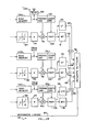
- FIG. 2 there is shown a functional block diagram of an attitude servo control system 30 of the present invention for controlling the orientation of a satellite platform 32 to which is mounted a position and rate sensor assembly 34.
- the orientation and rate of change of the satellite platform 32 is effected by six force inputs, namely roll force inputs 118 and 120 from a first thruster, herein arbitrarily designated the modulated roll thruster (MT) 18 and a second thruster, herein arbitrarily designated the unmodulated roll thruster (UT) 20, pitch force inputs 122 and 124 from respective first and second or modulated pitch thruster 22 and unmodulated pitch thruster 24, and yaw force inputs 126 and 128 from respective first and second or modulated and unmodulated yaw thrusters 26 and 28.
- Mechanical linkage 130 couples the satellite platform 32 with the position and rate sensor assembly 34.
- the position and rate sensor assembly 34 includes means for sensing position relative to the orientation of the satellite platform and means for sensing rate of change of attitude with reference to inertia of the satellite platform 32.
- a roll earth sensor 36 and a pitch earth sensor 38 are operative to extract roll and pitch attitude coordinates by reference to the position of the earth in a field of view relative to the satellite platform 32.
- Rate of change in inertia is provided through a digital integrated rate gyro assembly (DIRA) comprising DIRA units 40A for roll, 40B for pitch and 40C for yaw.
- DIRA digital integrated rate gyro assembly
- the earth sensors 36 and 38 form position loops with respect to movement of the satellite platform 32.
- the DIRAs 40A, 40B, and 40C form rate loops with respect to the change of position of the satellite platform 32.
- Each of these rate loops and position loops have associated therewith time constants relating to the propagation of feedback signals governing the modulation control of the modulated thrusters 18, 22 and 26. Because of the sensitivity of the satellite platform 32 to thrust inputs, the time constants would have to be minimized and the gain of the servo loops would have to be maximized if substantially real-time position and rate feedback were to be provided to control the modulation of the modulated thrusters 18, 22 and 26.
- the position error signals as for example, the signals on roll position error signal line 42 and yaw position error signal line 46 are extracted and stored during a calibration maneuver. They are subsequently employed during a change in velocity maneuver to generate a prebias command directed into the modulation control system of the thrusters thereby to overcome the time delay associated with real-time generation of initial position error signals.
- the change in attitude of the satellite platform 32 which has been effected by input of force by selected counteracting force input pairs under unmodulated conditions is measured during a calibration maneuver and a position error signal thereby generated is used for force calibration.
- the force calibration factor is applied as a prebias command bypassing the servo loop time delay associated with the position sensor.
- each servo loop namely the roll, pitch and yaw channels, which are ideally orthogonal, includes a lowpass filter section 48, 50 and 52 respectively, in the position loop and a highpass filter 54, 56 and 58 in the rate loop.
- These filters are designed to minimize the noise introduced into the loops as a nature of the sensed error signals, namely the position error signals on signal lines 42, 44 and 46 and the rate error signals on roll rate error signal line 60, pitch rate error signal line 62 and yaw rate error signal line 64.
- a rate amplifier 66, 68, 70 having associated therewith respective rate gains K,, for roll rate gain, K RP for pitch rate gain and K R y for yaw rate gain.
- Filtered position signals and rate signals are fed to respective summers 72, 74, 76, the outputs of which are each coupled to a second order compensation network 78, 80, 82.
- the compensation network 78, 80, 82 of each channel provides complex lead-lag compensation tailored to the characteristics of each of the three consolidated servo loops. While these compensation networks 78, 80 and 82 provide desirable servo loop control characteristics, they also introduce a relatively long delay between the error sensing mechanisms and the control mechanisms of the servo loop.
- a nonlinear deadband element 84, 86 and 88 is provided in each of the servo loops to take into account the acceptable limits of steady state attitude error. Otherwise, an inordinate amount of thruster fuel would be wasted while the servo system attempted to maintain attitude within a zero deadband.
- Common loop gain is represented by servo amplifier elements 90,92 and 94, the output of which is fed in negative feedback to respective command summers 96, 98 and 100.
- the output of the command summers 96, 98 and 100 is applied to respective pulsewidth, pulse frequency modulating devices (PWPF) 102, 104, 106, the paired outputs of which each control respective modulated thrusters 18, 22 and 26 and counteracting unmodulated thrusters 20, 24 and 28.
- PWPF pulse frequency modulating devices
- each control channel Associated with each control channel is an off-line feedforward channel which includes a roll error detector 108 in the roll channel, a pitch error detector 110 in the pitch channel and a yaw error detector 112 in the yaw channel.
- the respective error detectors 108, 110, 112 are operative to detect position error induced during start-up operation of the thruster pairs in a calibration maneuver.
- the respective errors are conveyed by a transmitter 114 to a ground station (not shown) or to storage in an on-board bias memory 116A, 116B, 116C wherein the error induced during each maneuver can be recorded for future reference and use.
- roll force inputs 118,120 can induce a change in attitude of the satellite platform 32 affecting most strongly the roll motion of the spacecraft while to a lesser degree pitch and yaw.
- the errors associated with the roll, pitch and yaw signals can be transmitted to a ground control station (not shown) for subsequent input as roll, pitch and yaw prebias commands during activation of the roll thrusters 18 and 20 in a charge of velocity maneuver.
- memory locations in the bias memory 116A, 11GB, 116C can be set aside for storing the primary and crosstalk errors induced during maneuvers involving the other thrusters.
- Signals representing the prebias can be extracted from the bias memory 116A, 116B, 116C or received through a receiver 132 and provided to a command module 134, 136, 138 for each channel.
- the command modules 134, 136, 138 generate the prebias commands to the summers 96, 98, 100 and any associated control commands to the PWPF 102, 104, 106 which in turn control the relative modulation of the paired thrusters.
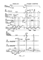
- Figure 4 illustrates phenomena related to attitude control of two axes arbitrarily designated roll and pitch. Attitude phenomena related to the third axis, namely yaw are not shown, as such phenomena are adequately illustrated by the phenomena related to the pitch axis. Specifically, there are two types of phenomena, namely, off-modulation of an active thruster during the firing of a thruster pair and on-modulation of an inactive thruster during firing of a thruster pair along an axis orthogonal to the inactive thruster.
- a roll command maneuver is illustrated.
- a roll command is initiated, typically from a ground station, as illustrated by a continuous roll maneuver command signal 200 following an off signal 210.
- Roll maneuver command signal 200 activates a thruster pair, such as the modulated roll thruster 18 and the unmodulated roll thruster 20 of Figure 2.
- the output of the unmodulated roll thruster 20 is represented by a signal 220, and the output of the modulated roll thruster 18 is illustrated by a signal 218.
- a roll error 224 is developed. The roll error eventually encounters one deadband threshold 226.
- the delayed roll error signal 228 activates the PWPF 102 to off-modulate the modulated roll thruster signal 218 for a period M beginning at a time AT following the crossover by the roll error 224 of the deadband threshold 226.
- thruster 18 is designated the modulated thruster.
- the off-modulation period is shown in signal 218.
- the unmodulated roll thruster 20 is active, as shown by signal 220, thereby causing a rapid reversal in attitude drift as illustrated by the roll error 224 during the corresponding interval.
- the length of the off-modulation period may be preset at an arbitrary figure intended to keep the roll error 224 within the deadband between first threshold 226 and second threshold 230. Nevertheless, due to the inherent bias or imbalance between the modulated and unmodulated roll thrusters while firing, the roll error 224 at the termination of a roll command may well be outside the permitted thresholds and may well cause subsequent roll thruster corrective maneuvers since the roll error signal 228 lags actual roll error 224. A post command pulse 232 of the unmodulated roll thruster signal 220 may therefore be generated in the servo loop to correct the roll error 224.
- the pitch attitude (and also the yaw attitude) may be effected by cross axis moment forces inducing a pitch error 234 followed by a pitch error signal 236 delayed by a loop delay AT.
- a pitch error signal 236 encounters the deadband threshold 238, a signal is generated which activates the appropriate pitch thruster, as represented by pitch thruster signal 240.
- the pitch thruster is active for a predetermined period sufficient to bring the pitch error back within deadband.
- a roll command 200 is actuated under external control and, according to the invention, a roll prebias 300 representing the ratio of disturbance torque to control torque is immediately initiated by a prebias command without reference to the roll errror signal 228.
- the roll prebias command is activated to initiate an automatic closed-loop selection of period P and off modulation interval T in the PWPF 102 during the roll command maneuver.
- the activated signal induces off-modulation periods in the modulated roll thruster signal 218 which are substantially independent of the initial roll error signal 228 with its inherent time delay following the actual roll error 224.
- the period P and the interval T initiated by the roll prebias command is closed-loop selected within the PWPF 102.
- the duration and frequency of the roll prebias 300 is selected to emulate the off-modulation pattern of the modulated roll thruster in the neighborhood of the deadband 226. This technique provides a remarkably accurate method for controlling roll error without the inherent delay of a closed-loop system.
- a prebias command applied to normally nonactive roll thrusters can also be used to on-modulate according to the same technique.
- a pitch prebias command 242 is operative to trigger a pitch thruster, as evidenced by a pitch thruster signal 244 to correct for pitch error 246.
- the pitch error 246 remains within the limits of the deadband.
- the on-modulation of the pitch thruster to control pitch error 246 within the deadband is independent of initial pitch attitude.
- the attitude control loop is activated to maintain the pitch error 246 or roll error 242 inside the deadband. Prototype testing has indicated that a proper prebias command will maintain attitudes control well within the boundaries of the deadband.
- FIG. 3 there is shown one embodiment of a PWPF 102 according to the invention coupled to an unmodulated thruster 20 and a modulated thruster 18.
- the PWPF 102 comprises a servo loop having a lowpass filter 250 coupled through a limiter 252 which in turns is coupled through a hysteresis controller 254, the output of which is fed back through a feedback line 256 in negative feedback to a summing junction 258. Control input into the summing junction 258 is provided from the summer 96 ( Figure 2).
- Table 1 sets forth the parameters for two different minimum duration command control pulses generated by the PWPF 102, the parameters being K M and T M of the lowpass filter 250, parameter L of the limiter 252 and parameters U ON , U OFF and U M of the hysteresis controller 254.
- the output of the hysteresis controller 254 is applied to a thruster logic detector 260, the function of which is to either on-modulate or off-modulate the thrusters depending on the activity states applied to the PWPF 102.
- the thruster logic detector 260 is responsive to control command input signals indicating whether the thruster pair should be activated or inactive, and it is responsive to three possible states of the hysteresis controller 254, namely positive error, negative error and zero error.
- Table 2 illustrates the input states and the possible output states of the thruster logic detector 260.
- the thrusters In the first state, in the absence of a control command to activate the thruster pairs and in the absence of any detected error, the thrusters, namely, a negative thruster and a positive thruster, are both inactive. In the absence of a control command to activate the thruster pair and in the presence of a positive error detected through the PWPF 102, the negative thruster is activated. In the absence of a control command to activate the thruster pairs and in the presence of a negative detected error, the positive thruster is activated. In the presence of a control command and in the absence of error, both the positive and the negative thrusters are activated. In the presence of a control command and a positive error, the negative thruster is activated and the positive thruster is off-modulated. In the presence of a control command and a negative error, the negative thruster is off-modulated and the positive thruster is on-modulated.
Landscapes
- Engineering & Computer Science (AREA)
- Remote Sensing (AREA)
- Chemical & Material Sciences (AREA)
- Combustion & Propulsion (AREA)
- Radar, Positioning & Navigation (AREA)
- Aviation & Aerospace Engineering (AREA)
- Automation & Control Theory (AREA)
- Control Of Position, Course, Altitude, Or Attitude Of Moving Bodies (AREA)
Description
- This invention relates to method and apparatus for spacecraft attitude control, and particularly to satellite transient attitude steady state attitude control during transfer orbit, stationkeeping, synchronous orbit and in general during any change in orbit velocity maneuver. In particular, the invention relates to thruster prebias control in order to compensate for imbalance and cross couplings due to misalignment among a plurality of attitude control thrusters of a spacecraft, such as a synchronous satellite during orbit adjustment.
- Spacecraft, particularly satellites designed for geosynchronous orbit and having large structural arrays of solar panels, are particularly susceptible to structural oscillation due to the transient disturbances induced by small rocket engines known as thrusters. The transient disturbances cause not only structural oscillations but can cause undesirable changes in spacecraft attitude which affect antenna direction and, therefore, signal target and signal strength. The problem of spacecraft dynamics and disturbance torque is particularly acute during the orbit adjustment in the stationkeeping mode wherein the satellite attitude is controlled exclusively by gas thrusters.
- The closest known technique for the stabilization of a spacecraft to compensate for transients is described in a research study by Aerospatiale Cannes of France, entitled "Compatibilite' De La Stabilisation H. Sat Avec Une Mission TV Directe", Document No. 272/882 A, dated 25 December 1978 by P. Brunet. In this study, a technique was proposed wherein the attitude sensor of the satellite would be offset biased to compensate for the transients induced during the application of thrust. This technique presupposes that there will be attitude error induced which can be calibrated to thrust. However, such a technique is difficult to calibrate because of controller compensation delays. An inherently fast, i.e., wide bandwidth feedback loop would be required to render such a scheme functional. This has a number of inherent limitations and shortcomings such as susceptibility to nonlinearities of the thruster controller, substantial problems due to the uncertainties in the spacecraft dynamic parameters and undesired sesnsitivity to time delay and sensor phase lag.
- The following further patents were uncovered in a search of the prior art:
- U.S. Patent No. 4,325,124 to Renner discloses a system for controlling the direction of the momentum vector of a geosynchronous satellite. The Renner system compensates for disturbance torques applied to a satellite in a way which eliminates the requirement for a thruster control loop. The disturbance torque is employed as a compensating torque to superimposed an artificial misalignment on the incidental misalignment of the satellite's solar panels. The artificial misalignment causes the momentum vector of the satellite to be adjusted to the desired direction to restore the desired attitude. The technique, involving correction which uses solar pressure to correct for solar pressure-induced, misalignment, should not be confused with the present invention.
- U.S. Patent No. 4,174,819 to Bruederle et al. describes a controller for attitude stabilization of a satellite in which the controller generates signals to thrusters and includes correction capabilities to permit efficient attitude control. Specifically, the system employs a two thruster pulse dead-beat mechanism to minimize spacecraft nutation.
- U.S. Patent No. 3,572,618 to Willett describes a method for stabilizing aircraft and missiles in which signals representative of the actual state of an airframe are generated by transducers and compared with a command signal fed to a control system whereby the state of the airframe is controlled. The technique involves modifying the sampling rate with respect to the bending mode of frequencies of sampled data systems.
- U.S. Patent No. 3,490,719 to Cantor et al. describes an attitude control system for providing reliable unidirectional transfer between a coarse mode and a fine mode of target acquisition.
- U.S. Patent No. Re. 30,429 to Phillips discloses a technique for minimizing spacecraft nutation due to disturbing torques. A signal responsive control system operates the attitude or orbit-control forces or a combination of both to minimize spacecraft nutation. In particular, the technique of two-pulse dead-beat control is extended to the use of reaction torque from reaction wheels.
- U.S. Patent No. 4,023,752 to Pistiner et al. discloses the elimination of residual spacecraft nutation due to repulsive torques. A signal responsive control system operates repulsive forces of a spacecraft for a predetermined time corresponding to an integral number of nutation periods in order to eliminate spacecraft nutation.
- U.S. Patent No. 3,937,423 to Johansen discloses nutation and roll-error-angle correction. The system employs two-pulse dead-beat thruster control which includes feedback correction paths by which jet triggering thresholds can be adjusted.
- U.S. Patent No. 4,188,666 to Legrand et al. describes a method and system for torque control and energy storage in a spacecraft. The system is operative to control inertia and reaction wheels to achieve a desired physical orientation and spacecraft activity. It is an object of this invention to minimize disturbance torques. In this system, it is stored kinetic energy which is regulated for controlling a momentum wheel and spacecraft attitude.
- U.S. Patent No. 3,968,352 to Andeen describes a torque control system using a closed tachometer loop to minimize wheel drag torque, bearing noise and the like and to derive an improved torque command for a wheel control system. The torque control system employs pulse-width modulation to control reaction wheels. An error signal derived from the difference between an integrated torque-command signal and angular speed signal is coupled to the motor of a reaction wheel to produce a compensated output torque referenced to disturbance torques.
- U.S. Patent No. 3,624,367 to Hamilton et al. discloses a self-optimized and adaptive attitude control system employing on-off reaction thrusters. Pulse-width modulation is determined by measuring angular velocities of the vehicle in order to minimize the number of propulsion system activations and thereby to prolong thruster life. Means are provided for introducing compensation for the presence of a bias force. The control system does not contemplate elimination of offset error but rather is concerned only with minimizing thruster activity.
- U.S. Patent No. 3,409,251 to Lawson et al. discloses a servo system including compensation for undesirable signals such as those produced by the misalignment, offset and long term drift bias of transducers and error signals in an aircraft.
- U.S. Patent No. 3,330,503 to Love et al. discloses a re-entry guidance system for use with a lifting vehicle entering a planet's atmosphere at high velocity. The system is employed to control aerodynamic control surfaces. During re-entry, a linear accelerometer generates an output which is compared to a precomputed nominal acceleration curve from which an error signal is generated which in turn is added to a command signal to insure that an appropriate amount of force is produced by the associated control surface.
- EP-A-0101302 relates to an apparatus for controlling the attitude of a spacecraft with respect to each of three orthogonal axes, comprising means for imparting angular velocity to the spacecraft about each of the axes, means for measuring the angular deviation of the spacecraft with respect to a desired orientation of the spacecraft with respect to each of the axes and for measuring the angular velocity of the spacecraft about each of the axes. The apparatus further comprises means for periodically observing the output signal produced by the measuring means and creating in response thereto a pulse train signature for each axis tailored to maneuver the spacecraft towards its desired orientation with respect to that axis and means responsive to each pulse train signature for loading into a shift register and piecewise outputting therefrom signals for alternately switching on and off associated imparting means in accordance with the pulse train signature.
- According to a first aspect of the invention, there is provided a method for use in a spacecraft to counteract disturbance transients during a change in velocity maneuver, the spacecraft employing a plurality of thrusters, at least a first thruster and a second thruster being disposed to develop mutually counteractive moment arms of thrust relative to at least one axis through a center of mass of the spacecraft, said first thruster and said second thruster being capable of developing unequal moment arms of force, the method comprising the steps of storing prior to said manuever a value representative of an estimated disturbance torque thereafter modulating in response to said stored value one of said first and second thrusters during said maneuver to counteract an actual disturbance torque a sufficient amount to compensate for said actual disturbance torque in order to minimize a net position error without initially detecting said net position error, detecting said net position error, said net position error being indicative of a difference between said estimated disturbance torque and said actual disturbance torque with respect to said axis and thereafter modulating in response to a sum of said stored value and said net position error one of said first and second thrusters during said maneuver to counteract said actual disturbance torque to further minimise said net position error.
- In a second aspect of the invention, there is provided an apparatus for use in a spacecraft for independently modulating thruster discharge to counteract disturbance transients during a change in velocity maneuver, the spacecraft comprising a plurality of thrusters, at least a first thruster and a second thruster being disposed to develop mutually counteractive moment arms of thrust relative to at least one axis through a center of mass of said spacecraft, said first thruster and said second thruster being capable of developing unequal thrust, the appartus comprising means arranged to generate a value representative of an estimated net disturbance torque for storage prior to said maneuver, means arranged to modulate one of said first and second thrusters in response to said estimated disturbance torque value obtained following storage during said maneuver to counteract an actual disturbance torque a sufficient amount to compensate for said actual disturbance torque in order to minimize net position error without initially detecting said net position error, means for detecting said net position error, said net position error being indicative of a difference between said estimated disturbance torque and said actual disturbance torque with respect to said one axis, and means for combining said net position error and said estimated disturbance torque to produce a control value for controlling said modulating means during said maneuver.
- The invention has particular advantages in that the feedback loop of the servo control system need have only relatively low gain while still accurately controlling spacecraft attitude. Moreover, low gain permits a relatively low control bandwidth which is not sensitive to loop time delay, to sensor phase lag, to nonlinearity of the pulse-width/pulse-frequency thrust system or to parameter uncertainty.
- In a particular embodiment, a complex leadlag network with relatively long delay is included in the position control loop of a servo control system and a high pass function is included in the rate loop of the servo control system to provide damping of the control loop during a change in velocity maneuver.
- The invention will be better understood by reference to the following detailed description taken in connection with the accompanying drawings.
-
- Figure 1 is a simplified depiction of a spacecraft showing an arrangement of thrusters.
- Figure 2 is a block diagram of a three-axis thruster control system of a spacecraft in accordance with the invention.
- Figure 3 is a block diagram of a portion of the control system according to the invention.
- Figure 4 is a waveform diagram for illustrating a command maneuver according to the invention and a command maneuver of the prior art.
- Figure 1 illustrates the features of a
typical spacecraft 10, such as a geosynchronous satellite havingsolar panels spacecraft 10 includes aposition sensor 16, for example an earth position sensor pointed in the direction of the earth along the yaw axis ψ. Thespacecraft 10 is provided with at least three pairs of thrusters, namely rollthrusters spacecraft 10 around the roll axis Φ,pitch thrusters yaw thrusters spacecraft 10 so as not to change spacecraft attitude. Such a maneuver is extremely difficult because of difficulty in controlling thrust, thrust dynamics and the location of the center of mass. It is for this purpose that the present invention was developed. - Turning to Figure 2, there is shown a functional block diagram of an attitude
servo control system 30 of the present invention for controlling the orientation of asatellite platform 32 to which is mounted a position andrate sensor assembly 34. The orientation and rate of change of thesatellite platform 32 is effected by six force inputs, namely rollforce inputs pitch force inputs 122 and 124 from respective first and second or modulatedpitch thruster 22 andunmodulated pitch thruster 24, andyaw force inputs unmodulated yaw thrusters Mechanical linkage 130 couples thesatellite platform 32 with the position andrate sensor assembly 34. - The position and
rate sensor assembly 34 includes means for sensing position relative to the orientation of the satellite platform and means for sensing rate of change of attitude with reference to inertia of thesatellite platform 32. Specifically, aroll earth sensor 36 and apitch earth sensor 38 are operative to extract roll and pitch attitude coordinates by reference to the position of the earth in a field of view relative to thesatellite platform 32. Rate of change in inertia is provided through a digital integrated rate gyro assembly (DIRA) comprisingDIRA units 40A for roll, 40B for pitch and 40C for yaw. - The
earth sensors satellite platform 32. TheDIRAs satellite platform 32. Each of these rate loops and position loops have associated therewith time constants relating to the propagation of feedback signals governing the modulation control of the modulatedthrusters satellite platform 32 to thrust inputs, the time constants would have to be minimized and the gain of the servo loops would have to be maximized if substantially real-time position and rate feedback were to be provided to control the modulation of the modulatedthrusters error signal line 42 and yaw position error signal line 46 are extracted and stored during a calibration maneuver. They are subsequently employed during a change in velocity maneuver to generate a prebias command directed into the modulation control system of the thrusters thereby to overcome the time delay associated with real-time generation of initial position error signals. Specifically, according to the invention, the change in attitude of thesatellite platform 32 which has been effected by input of force by selected counteracting force input pairs under unmodulated conditions is measured during a calibration maneuver and a position error signal thereby generated is used for force calibration. The force calibration factor is applied as a prebias command bypassing the servo loop time delay associated with the position sensor. - The operation of the invention will be better understood by reference to a specific embodiment, as shown in Figure 2, and by reference to the timing diagrams of Figure 4. Referring first to Figure 2, each servo loop, namely the roll, pitch and yaw channels, which are ideally orthogonal, includes a
lowpass filter section highpass filter signal lines 42, 44 and 46 and the rate error signals on roll rateerror signal line 60, pitch rateerror signal line 62 and yaw rate error signal line 64. Also associated with each highpass filter in the rate loop is arate amplifier respective summers order compensation network compensation network compensation networks nonlinear deadband element - Common loop gain is represented by
servo amplifier elements respective command summers command summers thrusters unmodulated thrusters PWPF - Associated with each control channel is an off-line feedforward channel which includes a
roll error detector 108 in the roll channel, apitch error detector 110 in the pitch channel and ayaw error detector 112 in the yaw channel. Therespective error detectors transmitter 114 to a ground station (not shown) or to storage in an on-board bias memory satellite platform 32 affecting most strongly the roll motion of the spacecraft while to a lesser degree pitch and yaw. The errors associated with the roll, pitch and yaw signals can be transmitted to a ground control station (not shown) for subsequent input as roll, pitch and yaw prebias commands during activation of theroll thrusters bias memory 116A, 11GB, 116C can be set aside for storing the primary and crosstalk errors induced during maneuvers involving the other thrusters. - Signals representing the prebias can be extracted from the
bias memory receiver 132 and provided to acommand module command modules summers PWPF - Referring to Figure 4, there is shown in comparison timing diagrams of control functions of the prior art (left column) and of the present invention (right column). Figure 4 illustrates phenomena related to attitude control of two axes arbitrarily designated roll and pitch. Attitude phenomena related to the third axis, namely yaw are not shown, as such phenomena are adequately illustrated by the phenomena related to the pitch axis. Specifically, there are two types of phenomena, namely, off-modulation of an active thruster during the firing of a thruster pair and on-modulation of an inactive thruster during firing of a thruster pair along an axis orthogonal to the inactive thruster.
- For the purpose of explanation, a roll command maneuver is illustrated. A roll command is initiated, typically from a ground station, as illustrated by a continuous roll
maneuver command signal 200 following anoff signal 210. Rollmaneuver command signal 200 activates a thruster pair, such as the modulatedroll thruster 18 and theunmodulated roll thruster 20 of Figure 2. The output of theunmodulated roll thruster 20 is represented by asignal 220, and the output of the modulatedroll thruster 18 is illustrated by asignal 218. Because of thrust imbalances as between the modulated roll thruster and the unmodulated roll thruster, aroll error 224 is developed. The roll error eventually encounters onedeadband threshold 226. However, there is an inherent delay AT associated with the servo loop due to time delays between the actual change in attitude and the signal responsive to the sensor. The delayedroll error signal 228 activates thePWPF 102 to off-modulate the modulatedroll thruster signal 218 for a period M beginning at a time AT following the crossover by theroll error 224 of thedeadband threshold 226. Hence,thruster 18 is designated the modulated thruster. The off-modulation period is shown insignal 218. For the interval M ofsignal 218, theunmodulated roll thruster 20 is active, as shown bysignal 220, thereby causing a rapid reversal in attitude drift as illustrated by theroll error 224 during the corresponding interval. The length of the off-modulation period may be preset at an arbitrary figure intended to keep theroll error 224 within the deadband betweenfirst threshold 226 andsecond threshold 230. Nevertheless, due to the inherent bias or imbalance between the modulated and unmodulated roll thrusters while firing, theroll error 224 at the termination of a roll command may well be outside the permitted thresholds and may well cause subsequent roll thruster corrective maneuvers since theroll error signal 228 lagsactual roll error 224. A post command pulse 232 of the unmodulatedroll thruster signal 220 may therefore be generated in the servo loop to correct theroll error 224. - During a roll maneuver, the pitch attitude (and also the yaw attitude) may be effected by cross axis moment forces inducing a
pitch error 234 followed by apitch error signal 236 delayed by a loop delay AT. As the pitch error signal 236 encounters thedeadband threshold 238, a signal is generated which activates the appropriate pitch thruster, as represented bypitch thruster signal 240. The pitch thruster is active for a predetermined period sufficient to bring the pitch error back within deadband. Thus has the attitude control system of the prior art operated. - In the right column of Figure 4 are shown phenomena of the present invention. A
roll command 200 is actuated under external control and, according to the invention, a roll prebias 300 representing the ratio of disturbance torque to control torque is immediately initiated by a prebias command without reference to theroll errror signal 228. The roll prebias command is activated to initiate an automatic closed-loop selection of period P and off modulation interval T in thePWPF 102 during the roll command maneuver. The activated signal induces off-modulation periods in the modulatedroll thruster signal 218 which are substantially independent of the initialroll error signal 228 with its inherent time delay following theactual roll error 224. The period P and the interval T initiated by the roll prebias command is closed-loop selected within thePWPF 102. The duration and frequency of the roll prebias 300 is selected to emulate the off-modulation pattern of the modulated roll thruster in the neighborhood of thedeadband 226. This technique provides a remarkably accurate method for controlling roll error without the inherent delay of a closed-loop system. - Whereas a prebias command may be used to off-modulate an activated roll thruster, a prebias command applied to normally nonactive roll thrusters can also be used to on-modulate according to the same technique. For example, a
pitch prebias command 242 is operative to trigger a pitch thruster, as evidenced by apitch thruster signal 244 to correct forpitch error 246. Thepitch error 246 remains within the limits of the deadband. The on-modulation of the pitch thruster to controlpitch error 246 within the deadband is independent of initial pitch attitude. On the other hand, the attitude control loop is activated to maintain thepitch error 246 orroll error 242 inside the deadband. Prototype testing has indicated that a proper prebias command will maintain attitudes control well within the boundaries of the deadband. - Referring to Figure 3, there is shown one embodiment of a
PWPF 102 according to the invention coupled to anunmodulated thruster 20 and a modulatedthruster 18. ThePWPF 102 comprises a servo loop having alowpass filter 250 coupled through alimiter 252 which in turns is coupled through a hysteresis controller 254, the output of which is fed back through afeedback line 256 in negative feedback to a summingjunction 258. Control input into the summingjunction 258 is provided from the summer 96 (Figure 2). Table 1 sets forth the parameters for two different minimum duration command control pulses generated by thePWPF 102, the parameters being KM and TM of thelowpass filter 250, parameter L of thelimiter 252 and parameters UON, UOFF and UM of the hysteresis controller 254.
- The output of the hysteresis controller 254 is applied to a
thruster logic detector 260, the function of which is to either on-modulate or off-modulate the thrusters depending on the activity states applied to thePWPF 102. Thethruster logic detector 260 is responsive to control command input signals indicating whether the thruster pair should be activated or inactive, and it is responsive to three possible states of the hysteresis controller 254, namely positive error, negative error and zero error. Table 2 illustrates the input states and the possible output states of thethruster logic detector 260.
- There are six possible states. In the first state, in the absence of a control command to activate the thruster pairs and in the absence of any detected error, the thrusters, namely, a negative thruster and a positive thruster, are both inactive. In the absence of a control command to activate the thruster pair and in the presence of a positive error detected through the
PWPF 102, the negative thruster is activated. In the absence of a control command to activate the thruster pairs and in the presence of a negative detected error, the positive thruster is activated. In the presence of a control command and in the absence of error, both the positive and the negative thrusters are activated. In the presence of a control command and a positive error, the negative thruster is activated and the positive thruster is off-modulated. In the presence of a control command and a negative error, the negative thruster is off-modulated and the positive thruster is on-modulated.
Claims (9)
Applications Claiming Priority (2)
| Application Number | Priority Date | Filing Date | Title |
|---|---|---|---|
| US487364 | 1983-04-21 | ||
| US06/487,364 US4537375A (en) | 1983-04-21 | 1983-04-21 | Method and apparatus for thruster transient control |
Publications (4)
| Publication Number | Publication Date |
|---|---|
| EP0148550A2 EP0148550A2 (en) | 1985-07-17 |
| EP0148550A3 EP0148550A3 (en) | 1986-02-12 |
| EP0148550B1 true EP0148550B1 (en) | 1990-06-20 |
| EP0148550B2 EP0148550B2 (en) | 1998-03-04 |
Family
ID=23935437
Family Applications (1)
| Application Number | Title | Priority Date | Filing Date |
|---|---|---|---|
| EP84302734A Expired - Lifetime EP0148550B2 (en) | 1983-04-21 | 1984-04-24 | Method and apparatus for thruster transient control |
Country Status (5)
| Country | Link |
|---|---|
| US (1) | US4537375A (en) |
| EP (1) | EP0148550B2 (en) |
| JP (1) | JPS59206300A (en) |
| CA (1) | CA1219848A (en) |
| DE (1) | DE3482562D1 (en) |
Families Citing this family (50)
| Publication number | Priority date | Publication date | Assignee | Title |
|---|---|---|---|---|
| US4725024A (en) * | 1985-11-15 | 1988-02-16 | Ford Aerospace & Communications Corporation | Method for spinning up a three-axis controlled spacecraft |
| JP2518212B2 (en) * | 1986-06-26 | 1996-07-24 | 日本電気株式会社 | Orbit control method for artificial satellites |
| US4767084A (en) * | 1986-09-18 | 1988-08-30 | Ford Aerospace & Communications Corporation | Autonomous stationkeeping for three-axis stabilized spacecraft |
| EP0333808B1 (en) * | 1987-09-16 | 1993-11-24 | Deutsche Aerospace AG | Device for regulating a set value and/or for stabilizing freely moving objects with stored spin |
| US4848706A (en) * | 1988-02-29 | 1989-07-18 | Ford Aerospace Corporation | Spacecraft attitude control using coupled thrusters |
| US5124925A (en) * | 1990-01-16 | 1992-06-23 | Space Systems/Loral, Inc. | Method for controlling east/west motion of a geostationary satellite |
| US5130931A (en) * | 1990-07-13 | 1992-07-14 | General Electric Company | Spacecraft attitude and velocity control system |
| US5222023A (en) * | 1991-04-02 | 1993-06-22 | Space Systems/Loral, Inc. | Compensated transition for spacecraft attitude control |
| US5140525A (en) * | 1991-07-31 | 1992-08-18 | General Electric Company | Unified spacecraft attitude control system |
| DE4129628A1 (en) * | 1991-09-06 | 1993-03-18 | Deutsche Aerospace | METHOD AND DEVICE FOR CONTROLLING THE POSITION OF A THREE-AXIS-STABILIZED SPIRAL VEHICLE |
| US5205518A (en) * | 1991-11-25 | 1993-04-27 | General Electric Co. | Gyroless yaw control system for a three axis stabilized, zero-momentum spacecraft |
| CA2080612A1 (en) * | 1991-11-27 | 1993-05-28 | Douglas J. Bender | Method and apparatus for compensating for magnetic disturbance torques on a satellite |
| FR2697651B1 (en) * | 1992-10-29 | 1995-02-03 | Aerospatiale | Method and apparatus for calibrating the gyros of a stabilized 3-axis satellite. |
| US5562266A (en) * | 1992-10-29 | 1996-10-08 | Aerospatiale Societe Nationale Industrielle | Rate gyro calibration method and apparatus for a three-axis stabilized satellite |
| US5400252A (en) * | 1992-12-22 | 1995-03-21 | Space Systems/Loral, Inc. | Spacecraft East/West orbit control during a North or South stationkeeping maneuver |
| US5411227A (en) * | 1992-12-23 | 1995-05-02 | Hughes Aircraft Company | Satellite thruster uncertainty estimation in transition mode |
| US5459669A (en) * | 1994-02-14 | 1995-10-17 | Space Systems/Loral, Inc. | Control system and method for spacecraft attitude control |
| US5582368A (en) * | 1995-01-23 | 1996-12-10 | Martin Marietta Corp. | Reaction wheel speed observer system |
| US6439509B1 (en) * | 1995-07-03 | 2002-08-27 | Space Systems/Loral, Inc. | Pre-bias scheme for roll momentum unloads on pitch momentum bias/yaw reaction wheel spacecraft |
| US5752675A (en) * | 1995-07-03 | 1998-05-19 | Space Systems/Loral, Inc. | Thruster control of yaw without yaw measurements |
| US5655735A (en) * | 1995-07-03 | 1997-08-12 | Space Systems Loral, Inc. | Post transition momentum management |
| US5850993A (en) * | 1995-08-25 | 1998-12-22 | Martin Marietta Corp. | Spacecraft thruster operation for improved orbital maneuver accuracy |
| US5646847A (en) * | 1995-08-25 | 1997-07-08 | Martin Marietta Corp. | Universal thruster selection logic for spacecraft attitude control |
| US5687933A (en) * | 1995-08-30 | 1997-11-18 | Martin Marietta Corporation | Attitude control for spacecraft with movable appendages such as solar panels |
| US5806804A (en) * | 1996-11-12 | 1998-09-15 | Lockheed Martin Corp. | Adaptive harmonic disturbance compensation system |
| US5984237A (en) * | 1997-02-13 | 1999-11-16 | Lockheed Martin Corp. | Delta-V targeting system for three-axis controlled spacecraft |
| US6125310A (en) * | 1997-07-18 | 2000-09-26 | Space Systems/Loral, Inc. | Thruster on time signaling with flexure compensation avoidance |
| US6373023B1 (en) | 1999-03-02 | 2002-04-16 | General Dynamics (Ots) Aerospace, Inc. | ARC discharge initiation for a pulsed plasma thruster |
| US6445981B1 (en) * | 2000-03-02 | 2002-09-03 | Space Systems/Loral, Inc. | Controller and control method for satellite orbit-keeping maneuvers |
| RU2211786C1 (en) * | 2002-01-18 | 2003-09-10 | Федеральное государственное унитарное предприятие Московское опытно-конструкторское бюро "Марс" | Method of correction of parameters of program of change of longitudinal motion at terminal control of cryogenic stage guidance to preset orbit |
| US6732977B1 (en) | 2002-02-11 | 2004-05-11 | Lockheed Martin Corporation | System for on-orbit correction of spacecraft payload pointing errors |
| US6695263B1 (en) | 2002-02-12 | 2004-02-24 | Lockheed Martin Corporation | System for geosynchronous spacecraft rapid earth reacquisition |
| US7051980B2 (en) * | 2002-02-26 | 2006-05-30 | Lockheed Martin Corporation | Efficient orbit sparing system for space vehicle constellations |
| US6629672B1 (en) | 2002-03-08 | 2003-10-07 | Lockheed Martin Corporation | Sun sensor alignment compensation system |
| US6702234B1 (en) | 2002-03-29 | 2004-03-09 | Lockheed Martin Corporation | Fault tolerant attitude control system for zero momentum spacecraft |
| RU2223894C1 (en) * | 2002-05-30 | 2004-02-20 | Федеральное государственное унитарное предприятие Московское опытно-конструкторское бюро "Марс" | Method of forming terminal control of guidance of cryogenic stage in preset orbit |
| RU2254271C2 (en) * | 2003-06-27 | 2005-06-20 | Федеральное государственное унитарное предприятие Московское опытно-конструкторское бюро "Марс" (ФГУП МОКБ "Марс") | Method of correction of parameters of longitudinal motion change program at terminal control of cryogenic stage guidance on preset orbit |
| RU2282568C1 (en) * | 2005-02-16 | 2006-08-27 | Федеральное государственное унитарное предприятие Московское опытно-конструкторское бюро "Марс" (ФГУП МОКБ "Марс") | Method of forming program for orientation of cryogenic stage at terminal control of injection into preset orbit |
| US7835826B1 (en) | 2005-12-13 | 2010-11-16 | Lockheed Martin Corporation | Attitude determination system for yaw-steering spacecraft |
| RU2381965C1 (en) * | 2008-08-18 | 2010-02-20 | Открытое акционерное общество "Информационные спутниковые системы" имени академика М.Ф. Решетнева" | Method to simultaneously correct triaxially-stabilised spacecraft circular orbit inclination vector holding and period |
| RU2432595C1 (en) * | 2010-07-02 | 2011-10-27 | Федеральное государственное унитарное предприятие Московское опытно-конструкторское бюро "Марс" (ФГУП МОКБ "Марс") | Method of correcting parameters of upper-stage rocket orientation programme |
| US8998146B2 (en) * | 2012-11-21 | 2015-04-07 | Space Systems/Loral, Llc | Spacecraft momentum unload and station-keeping techniques |
| US9334068B2 (en) * | 2014-04-04 | 2016-05-10 | NOA Inc. | Unified orbit and attitude control for nanosatellites using pulsed ablative thrusters |
| CN105487378B (en) * | 2014-09-17 | 2018-08-24 | 上海新跃仪表厂 | A kind of rail, which drains, disturbs autonomous suppressing method |
| CN105589468B (en) * | 2016-03-08 | 2018-06-29 | 南京航空航天大学 | The bi-motor automatic trim method of three-axis satellite simulator |
| US10625882B2 (en) * | 2017-03-06 | 2020-04-21 | Effective Space Solutions Ltd. | Service satellite for providing in-orbit services using variable thruster control |
| CN108983801B (en) * | 2018-08-14 | 2021-05-28 | 北京航空航天大学 | A Spacecraft Anti-jamming Attitude Control Method Based on Dynamic Characteristics of Reaction Flywheel |
| US20210284361A1 (en) * | 2019-07-17 | 2021-09-16 | Skeyeon, Inc. | Systems and methods for attitude control for a satellite |
| RU2739645C1 (en) * | 2019-12-25 | 2020-12-28 | Федеральное государственное унитарное предприятие "Научно-производственный центр автоматики и приборостроения имени академика Н.А. Пилюгина" (ФГУП "НПЦАП") | Method of compensating loss of thrust by accelerating unit orientation machines |
| CN119929185B (en) * | 2024-12-31 | 2025-11-07 | 北京控制工程研究所 | A high-precision KBR phase center on-orbit calibration planning and control method |
Family Cites Families (17)
| Publication number | Priority date | Publication date | Assignee | Title |
|---|---|---|---|---|
| US30429A (en) * | 1860-10-16 | Blind-slat machine | ||
| US3330503A (en) * | 1964-08-10 | 1967-07-11 | Trw Inc | Re-entry guidance system |
| US3409251A (en) * | 1966-12-01 | 1968-11-05 | Sperry Rand Corp | Servo means having compensation for undesirable signals |
| US3572618A (en) * | 1967-11-01 | 1971-03-30 | Univ Iowa State Res Found Inc | Method for stabilizing aircraft and missiles |
| US3490719A (en) * | 1968-01-24 | 1970-01-20 | Nasa | Attitude control system |
| US3643897A (en) * | 1968-10-18 | 1972-02-22 | Communications Satellite Corp | Nutation correction system for spin-stabilized satellite |
| US3624367A (en) * | 1968-11-12 | 1971-11-30 | Gen Electric | Self-optimized and adaptive attitude control system |
| US3866025A (en) * | 1972-03-17 | 1975-02-11 | Rca Corp | Spacecraft attitude control system |
| US4023752A (en) * | 1973-12-10 | 1977-05-17 | Rca Corporation | Elimination of residual spacecraft nutation due to propulsive torques |
| US3937423A (en) * | 1974-01-25 | 1976-02-10 | Hughes Aircraft Company | Nutation and roll error angle correction means |
| US3968352A (en) * | 1974-05-17 | 1976-07-06 | Sperry Rand Corporation | Torque control system for reaction wheel assemblies and the like |
| US3984071A (en) * | 1974-08-29 | 1976-10-05 | Trw Inc. | Satellite nutation attenuation apparatus |
| FR2393364A1 (en) * | 1977-05-31 | 1978-12-29 | Aerospatiale | METHOD AND INTEGRATED SYSTEM FOR TORQUE CONTROL AND ENERGY CONDITIONING FOR A SPACE VEHICLE |
| DE2732201C2 (en) * | 1977-07-16 | 1983-01-13 | Messerschmitt-Bölkow-Blohm GmbH, 8000 München | Regulator for the attitude stabilization of a satellite |
| USRE30429E (en) | 1978-12-12 | 1980-11-04 | Rca Corporation | Minimization of residual spacecraft nutation due to disturbing torques |
| US4325124A (en) * | 1979-02-28 | 1982-04-13 | Organisation Europeenne De Recherches Spatiales | System for controlling the direction of the momentum vector of a geosynchronous satellite |
| US4599697A (en) * | 1982-08-11 | 1986-07-08 | Ford Aerospace & Communications Corporation | Digital PWPF three axis spacecraft attitude control |
-
1983
- 1983-04-21 US US06/487,364 patent/US4537375A/en not_active Expired - Lifetime
- 1983-12-22 CA CA000444133A patent/CA1219848A/en not_active Expired
-
1984
- 1984-04-20 JP JP59078776A patent/JPS59206300A/en active Granted
- 1984-04-24 DE DE8484302734T patent/DE3482562D1/en not_active Expired - Lifetime
- 1984-04-24 EP EP84302734A patent/EP0148550B2/en not_active Expired - Lifetime
Also Published As
| Publication number | Publication date |
|---|---|
| CA1219848A (en) | 1987-03-31 |
| JPS59206300A (en) | 1984-11-22 |
| US4537375A (en) | 1985-08-27 |
| EP0148550A2 (en) | 1985-07-17 |
| JPH0450239B2 (en) | 1992-08-13 |
| EP0148550B2 (en) | 1998-03-04 |
| DE3482562D1 (en) | 1990-07-26 |
| EP0148550A3 (en) | 1986-02-12 |
Similar Documents
| Publication | Publication Date | Title |
|---|---|---|
| EP0148550B2 (en) | Method and apparatus for thruster transient control | |
| EP0453096B1 (en) | Apparatus for inclined orbit attitude control of a satellite in an inclined orbit | |
| US5349532A (en) | Spacecraft attitude control and momentum unloading using gimballed and throttled thrusters | |
| US6296207B1 (en) | Combined stationkeeping and momentum management | |
| EP0225683B1 (en) | Method for spinning up a three-axis controlled spacecraft | |
| US5806804A (en) | Adaptive harmonic disturbance compensation system | |
| US6292722B1 (en) | Magnetic torquer control with thruster augmentation | |
| US4931942A (en) | Transition control system for spacecraft attitude control | |
| US5459669A (en) | Control system and method for spacecraft attitude control | |
| CA1196075A (en) | Digital pwpf three axis spacecraft attitude control | |
| EP0251692B1 (en) | Orbit control system for a satellite | |
| US4732354A (en) | Active damping of satellite nutation | |
| US5139218A (en) | Fast earth recovery procedure for earth-pointing satellites | |
| US5687933A (en) | Attitude control for spacecraft with movable appendages such as solar panels | |
| US5984237A (en) | Delta-V targeting system for three-axis controlled spacecraft | |
| WO1988010459A1 (en) | Nutation sensor and nutation control system for a dual-spin stabilized satellite | |
| LEBSOCK et al. | Double gimballed reaction wheel attitude control system for high altitude communications satellites | |
| US5308025A (en) | Spacecraft spin axis capture system and method | |
| USRE30429E (en) | Minimization of residual spacecraft nutation due to disturbing torques | |
| BARBERA et al. | The design of a two wheel momentum bias system for the attitude control of spacecraft in low altitude orbits | |
| Sreesawet et al. | Neural Networks Based Adaptive Controller for Attitude Control of All-Electric Satellites | |
| Brauch et al. | Orbit and Attitude Stabilization System for “Symphonie” Communications Satellite | |
| Fox | Attitude control subsystem performance of the RCA Series 3000 satellite | |
| Cavallo et al. | A re-entry capsule control system design for microgravity experiments | |
| MARKLEY et al. | A Zero-Gyro safemode controller for HST |
Legal Events
| Date | Code | Title | Description |
|---|---|---|---|
| PUAI | Public reference made under article 153(3) epc to a published international application that has entered the european phase |
Free format text: ORIGINAL CODE: 0009012 |
|
| AK | Designated contracting states |
Designated state(s): DE FR GB |
|
| PUAL | Search report despatched |
Free format text: ORIGINAL CODE: 0009013 |
|
| AK | Designated contracting states |
Designated state(s): DE FR GB |
|
| 17P | Request for examination filed |
Effective date: 19860123 |
|
| 17Q | First examination report despatched |
Effective date: 19871214 |
|
| GRAA | (expected) grant |
Free format text: ORIGINAL CODE: 0009210 |
|
| AK | Designated contracting states |
Kind code of ref document: B1 Designated state(s): DE FR GB |
|
| REF | Corresponds to: |
Ref document number: 3482562 Country of ref document: DE Date of ref document: 19900726 |
|
| ET | Fr: translation filed | ||
| PLBI | Opposition filed |
Free format text: ORIGINAL CODE: 0009260 |
|
| 26 | Opposition filed |
Opponent name: MESSERSCHMITT - BOELKOW - BLOHM GMBH, OTTOBRUNN Effective date: 19910320 |
|
| PLAB | Opposition data, opponent's data or that of the opponent's representative modified |
Free format text: ORIGINAL CODE: 0009299OPPO |
|
| R26 | Opposition filed (corrected) |
Opponent name: DEUTSCHE AEROSPACE AKTIENGESELLSCHAFT Effective date: 19910320 |
|
| REG | Reference to a national code |
Ref country code: GB Ref legal event code: 732E |
|
| REG | Reference to a national code |
Ref country code: FR Ref legal event code: TP |
|
| RAP2 | Party data changed (patent owner data changed or rights of a patent transferred) |
Owner name: SPACE SYSTEMS / LORAL INC. |
|
| APAC | Appeal dossier modified |
Free format text: ORIGINAL CODE: EPIDOS NOAPO |
|
| APAC | Appeal dossier modified |
Free format text: ORIGINAL CODE: EPIDOS NOAPO |
|
| APCC | Communication from the board of appeal sent |
Free format text: ORIGINAL CODE: EPIDOS OBAPO |
|
| APCC | Communication from the board of appeal sent |
Free format text: ORIGINAL CODE: EPIDOS OBAPO |
|
| APAC | Appeal dossier modified |
Free format text: ORIGINAL CODE: EPIDOS NOAPO |
|
| APAC | Appeal dossier modified |
Free format text: ORIGINAL CODE: EPIDOS NOAPO |
|
| PLAW | Interlocutory decision in opposition |
Free format text: ORIGINAL CODE: EPIDOS IDOP |
|
| PUAH | Patent maintained in amended form |
Free format text: ORIGINAL CODE: 0009272 |
|
| STAA | Information on the status of an ep patent application or granted ep patent |
Free format text: STATUS: PATENT MAINTAINED AS AMENDED |
|
| 27A | Patent maintained in amended form |
Effective date: 19980304 |
|
| AK | Designated contracting states |
Kind code of ref document: B2 Designated state(s): DE FR GB |
|
| ET3 | Fr: translation filed ** decision concerning opposition | ||
| REG | Reference to a national code |
Ref country code: GB Ref legal event code: IF02 |
|
| PGFP | Annual fee paid to national office [announced via postgrant information from national office to epo] |
Ref country code: FR Payment date: 20020401 Year of fee payment: 19 |
|
| PGFP | Annual fee paid to national office [announced via postgrant information from national office to epo] |
Ref country code: GB Payment date: 20020417 Year of fee payment: 19 |
|
| PGFP | Annual fee paid to national office [announced via postgrant information from national office to epo] |
Ref country code: DE Payment date: 20020418 Year of fee payment: 19 |
|
| PG25 | Lapsed in a contracting state [announced via postgrant information from national office to epo] |
Ref country code: GB Free format text: LAPSE BECAUSE OF NON-PAYMENT OF DUE FEES Effective date: 20030424 |
|
| PG25 | Lapsed in a contracting state [announced via postgrant information from national office to epo] |
Ref country code: DE Free format text: LAPSE BECAUSE OF NON-PAYMENT OF DUE FEES Effective date: 20031101 |
|
| GBPC | Gb: european patent ceased through non-payment of renewal fee | ||
| PG25 | Lapsed in a contracting state [announced via postgrant information from national office to epo] |
Ref country code: FR Free format text: LAPSE BECAUSE OF NON-PAYMENT OF DUE FEES Effective date: 20031231 |
|
| REG | Reference to a national code |
Ref country code: FR Ref legal event code: ST |
|
| APAH | Appeal reference modified |
Free format text: ORIGINAL CODE: EPIDOSCREFNO |