EP0147242A2 - Vibration isolating devices - Google Patents
Vibration isolating devices Download PDFInfo
- Publication number
- EP0147242A2 EP0147242A2 EP84309150A EP84309150A EP0147242A2 EP 0147242 A2 EP0147242 A2 EP 0147242A2 EP 84309150 A EP84309150 A EP 84309150A EP 84309150 A EP84309150 A EP 84309150A EP 0147242 A2 EP0147242 A2 EP 0147242A2
- Authority
- EP
- European Patent Office
- Prior art keywords
- vibration
- restricted passage
- vibration isolating
- frequency
- isolating device
- Prior art date
- Legal status (The legal status is an assumption and is not a legal conclusion. Google has not performed a legal analysis and makes no representation as to the accuracy of the status listed.)
- Granted
Links
Images


Classifications
-
- F—MECHANICAL ENGINEERING; LIGHTING; HEATING; WEAPONS; BLASTING
- F16—ENGINEERING ELEMENTS AND UNITS; GENERAL MEASURES FOR PRODUCING AND MAINTAINING EFFECTIVE FUNCTIONING OF MACHINES OR INSTALLATIONS; THERMAL INSULATION IN GENERAL
- F16F—SPRINGS; SHOCK-ABSORBERS; MEANS FOR DAMPING VIBRATION
- F16F13/00—Units comprising springs of the non-fluid type as well as vibration-dampers, shock-absorbers, or fluid springs
- F16F13/04—Units comprising springs of the non-fluid type as well as vibration-dampers, shock-absorbers, or fluid springs comprising both a plastics spring and a damper, e.g. a friction damper
- F16F13/06—Units comprising springs of the non-fluid type as well as vibration-dampers, shock-absorbers, or fluid springs comprising both a plastics spring and a damper, e.g. a friction damper the damper being a fluid damper, e.g. the plastics spring not forming a part of the wall of the fluid chamber of the damper
- F16F13/08—Units comprising springs of the non-fluid type as well as vibration-dampers, shock-absorbers, or fluid springs comprising both a plastics spring and a damper, e.g. a friction damper the damper being a fluid damper, e.g. the plastics spring not forming a part of the wall of the fluid chamber of the damper the plastics spring forming at least a part of the wall of the fluid chamber of the damper
- F16F13/10—Units comprising springs of the non-fluid type as well as vibration-dampers, shock-absorbers, or fluid springs comprising both a plastics spring and a damper, e.g. a friction damper the damper being a fluid damper, e.g. the plastics spring not forming a part of the wall of the fluid chamber of the damper the plastics spring forming at least a part of the wall of the fluid chamber of the damper the wall being at least in part formed by a flexible membrane or the like
Definitions
- This invention relates to a vibration isolating device for damping vibrations from vibration source.
- the vibration isolating device generally called as a rubber vibration isolator is used, for example, as an engine mount for automobile vehicles, whereby vibra-. tions from an internal-combustion engine are absorbed so as not to be transmitted to a vehicle chassis.
- a vibration isolating device comprising two vibration-damping liquid chambers separated by a partition member provided with a restricted-passage, in which vibrations from vibration source are absorbed by a flow resistance subjected to the liquid when the vibration is transmitted to the one chamber to thereby flow the liquid from the one chamber to the other through the restricted passage.
- the vibration transmitting force is lowered as far as possible at various vibration frequencies, but also the damping force is developed at a frequency range of 10-20 Hz corresponding to the vibration from the engine.
- a vibration isolating device comprising a main vibration-absorbing body composed mainly of an elastomeric material and provided at its inside with a hollow chamber containing a vibration-damping liquid therein, and plural partition members each provided with a restricted passage therein to divide said hollow chamber into at least three small liquid chambers, one of said restricted passages having a sectional area larger than that of the other remaining restricted passages.
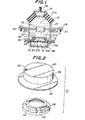
- Fig. 1 is sectionally shown a first embodiment of the vibration isolating device according to the invention.
- This vibration isolating device is used as an engine mount for automobile vehicle.
- the vibration isolating device comprises a hollow bottom cylinder 10, to the inside of which at its axially middle position is clamped an outer peripheral portion of a ring plate 12. Further, a lower diaphragm 14 is clamped at its outer peripheral portion between the ring plate 12 and a step portion 10A of the cylinder 10 formed just beneath the ring plate 12 and forms an air chamber 16 together with a bottom plate 10B of the cylinder 10. This air chamber 16 may be communicated with an exterior through a hole formed in the bottom plate 10B.
- the upper end portion of the bottom cylinder 10 is fixed to a lower end portion of a joint cylinder 20 through an upper partition member 18.
- the upper end portion of the joint cylinder 20 is enlarged upward, to which is bonded a rubber member 22 as a vibration-absorbing main body by vulcanization.
- a rubber member 22 as a vibration-absorbing main body by vulcanization.
- other elastomeric materials may be used instead of the rubber member 22.
- the upper end portion of the rubber member 22 is bonded by vulcanization to a base plate 24 provided with a fitting bolt 26.
- the base plate 24 is used for carrying an engine (not shown), wherein the engine is fixed to the base plate 24 through the fitting bolt 26.
- a flange 28 is protruded outward from the lower end portion of the joint cylinder 20 and provided with plural fitting bolts 30 for fixing a vehicle chassis (not shown).
- a closed space is defined as a liquid chamber by the bottom cylinder 10, lower diaphragm 14, joint cylinder 20, rubber member 22 and base plate 24 and filled with a vibration-damping liquid such as water or the like.
- the upper partition member 18 divides the closed space into an upper liquid chamber 37A and a middle liquid chamber 37B. Both the liquid chambers are communicated with each other through a cylindrical hole 38 formed in the center of the partition member 18 as a restricted passage.
- the ring plate 12 clamped together with the lower diaphragm 14 to the bottom cylinder 10 serves as a lower partition member and comprises a central upheaved portion composed of a cylindrical part 58 and a ceiling part 60, which divides the closed space into the middle liquid chamber 37B and a lower liquid chamber 37C.
- the closed space is divided into the upper liquid chamber 37A, middle liquid chamber 37B and lower liquid chamber 37C by the upper partition member 18 and the lower partition member 12.
- the ring plate 12 is formed by lapping and fixing two plate materials 56 and 62.
- the plate material 56 is a hat-shaped body provided with the cylindrical part 58 and the ceiling part 60 and made, for example, by deep drawing of a disc metal sheet.
- To a recess bottom of the plate material 56 is fixed the plate material 62 of an annular metal sheet provided at its outer peripheral portion with a ring-like depression 63.
- a restricted passage or an orifice 64 is formed between the plate material 56 and the plate material 62, and communicated with the middle liquid chamber 37B through an opening 66 formed in the ceiling part 60 of the plate material 56 on the one hand and with the lower liquid chamber 37C through an opening 68 formed in the plate material 62 on the other hand.
- the partition member 18 provided with the cylindrical hole 38 is disposed at a side of vibration source or near the base plate 24.
- the orifice 64 is small in the diameter and long in the axial length as compared with the cylindrical hole 38. (The axial length of the orifice 64 is more than 5 times the sectional area thereof.)
- the flange 28 is mounted on the vehicle chassis and fixed thereto through the fitting bolts 30, while the engine for automobile vehicle is fixed to the base plate 24 through the fitting bolt 26.
- the dead weight of the engine is applied to the base plate 24 to increase the pressure inside the upper liquid chamber 37A.
- Such an increase of the pressure is transmitted to the middle liquid chamber 37B through the cylindrical hole 38 and further to the lower liquid chamber 37C through the orifice 64, whereby the lower diaphragm 14 is displaced toward a direction of contracting the air chamber 16.
- vibrations generated from the engine are transmitted to the device through the base plate 24.
- the rubber member 22 can absorb the vibration owing to its damping function based on the internal friction.
- the vibration-damping effect is further enhanced by the viscosity resistance caused in the flowing of the liquid through the restricted passage having a long axial length and a small sectional area or the orifice 64.
- the cylindrical hole 38 hardly develops the vibration-damping action because it has a large sectional area.
- the vibration-damping effect against vibrations of low frequency and large amplitude is large because the orifice 64 is a C-shaped, long restricted passage defined between the plate material 56 and the plate material 62.
- the axial length of the orifice 64 may optionally be adjusted by changing a relative angle between the openings 66 and 68 in the fixing of the plate material 62 to the plate material 56 by welding or the like.
- the bottom cylinder 10 may be made from a metal or a flexible elastomer. As the bottom cylinder is rendered flexible, the resonance frequency produced in the cylindrical hole 38 and the orifice 64 becomes lower, from which a proper resonance frequency can be selected.
- the upper liquid chamber 37A Assuming that the volume of the upper liquid chamber 37A is changed by A cm 3 when the rubber member 22 is bent by 1 cm under the application of the engine dead weight, if the upper liquid chamber 37A has an effective diameter of Do cm and an effective sectional area of ⁇ (D o/ 2) 2 and the cylindrical hole 38 has a length of L cm and a diameter of D cm, it is required to satisfy D/D o of not less than 1/3 and L/D 2 of not more than 1/3.
- dynamic factor means a ratio of dynamic spring constant to static spring constant.
- Fig. 3a shows a relation between the frequency and the dynamic factor in the device of Fig. 1
- Fig. 3b shows a relation between the frequency and the loss factor (tan 6) in the same device, from which it is understood that a large vibration-damping force can be obtained at an arbitrary frequency.
- a second embodiment of the vibration isolating device according to the invention which is a modification of the device shown in Fig. 1. That is, the ring plate or partition member 18 is provided with an opening 18A instead of the cylindrical hole 38. Further, a rubber member 70 having a hardness larger than that of the rubber member 22 is secured at its one end to an upper surface of the base blate 24 and at the other end to a fitting plate 71 for an engine provided with the fitting bolt 26. Moreover, the bottom plate 10B is provided at its outer bottom surface with a fitting bolt 30'.
- the building-up of the dynamic factor in the liquid column resonance can be made low as shown in Fig. 5.
- the rubber member 70 may also be disposed at the side of the bottom cylinder 10.
- a third embodiment of the vibration isolating device which is also a modification of the device shown in Fig. 1. That is, the partition member 18 is provided with an opening 18A instead of the cylindrical hole 38. Further, the plate material 56 constituting a part of the partition member 12 is provided at the center of the ceiling portion 60 with a circular hole 60A for receiving a movable disc body 70.
- This movable disc body 70 is provided at its outer peripheral edge with a flange 74 of J -shape in section and is possible to move in up and down direction by a slight amount (about 0.1-0.05 mm) with respect to the peripheral edge.of the circular hole 60A, whereby the pressure increase can be suppressed under high frequency vibrations.
- the fitting position of the movable disc body 72 is not restricted as far as it is existent between the middle liquid chamber 37B and the lower liquid chamber 37C.
- a fourth embodiment of the vibration isolating device according to the invention which is a further modification of the device shown in Fig. 4.
- the partition member 12 is formed by clamping an annular plate 56A between the bottom cylinder 10 and the bottom plate 10B thereof and inserting the plate material 56 provided at its outer peripheral edge with a flange 74 of D -shape in section into a hole of the annular plate 56A.
- a fifth embodiment of the vibration isolating device according to the invention which is a modification of the device shown in Fig. 6. That is, a rubber membrane 76 is fixed to a peripheral edge of the circular hole 60A formed in the central portion of the ceiling portion 60 instead of the movable disc body 72. In this case, wire cords or the like are embedded in the rubber membrane 76 to restrict the moving quantity of the membrane 76. Thus, the rubber membrane 76 plays the same role as the movable disc body 72.
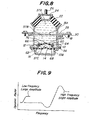
- Fig. 9 shows the relation between the frequency and the dynamic factor in the devices of Figs.6, 7 and 8.
- Figs. 10a and 10b show experimental results in the device of Fig. 8.
- the upper liquid chamber 37A is filled with 70 cc of an antifreezing liquid
- each of the middle and lower liquid chambers 37B, 37C is filled with 30 cc of an antifreezing liquid
- the air chamber 16 is filled with 70 cc of air
- the rubber member has a dynamic spring constant of 120 kgf/cm and tan ⁇ (loss factor) of 0.1
- the bottom cylinder 10 is an elastomer having the same volume elasticity as that of the rubber member and a dynamic spring constant of 220 kgf/cm.
- the opening 18A has a diameter of 4 cm and a length of 0.5 cm and the orifice 64 has a diameter of 0.8 cm and a length of 5.0 cm.
- tan 6 can be made large against vibrations having a frequency of 10-15 Hz and an amplitude of ⁇ 1 mm as shown in Figs. 10a and 10b.
- the device since the device has the rubber membrane 76 as a movable member, there is no building-up of the dynamic spring constant against vibrations having a frequency of about 10 Hz and a small amplitude of about ⁇ 0.05 mm and tan ⁇ is not produced at a frequency of about 10 Hz.
- the dynamic spring constant can considerably be reduced at a frequency of 100-180 Hz due to the presence of the opening 18A.
- Fig. 11 is shown a sixth embodiment of the vibration isolating device according to the invention, which is also a modification of Fig. 4.
- a ring member 78 is embedded in the rubber member 22 to adjust the elastic force of the rubber member 22.
- a regulating plate 80 is integrally fixed to the top surface of the base plate 24 and extends outward therefrom.
- the outer peripheral portion of the regulating plate 80 is bent downward at a right angle to form a regulation part 82.
- An annular rubber stopper 84 is secured to the inner surface of the regulation part 82 and is opposite to a rubber member 86 fixed to the outer peripheral surface of the joint cylinder 20. In this embodiment, therefore, the movement of the base plate 24 in the lateral direction can be restricted.
- Fig. 13 is shown an eighth embodiment of the vibration isolating device according to the invention, wherein the partition member 18 is formed by lapping and fixing two plate materials 90 and 92 in the same shape as in the ring plate 12 to form an orifice 88.
- the orifice 88 is large in the sectional area and short in the axial length as compared with the orifice 64 of the ring plate 12.
- Fig. 14 is shown a ninth embodiment of the vibration isolating device according to the invention, wherein the ring plate 12 composed of the two plate material 56 and 62 as shown in Fig. 2 is clamped at its outer periphery between a ring plate member 12A and the lower diaphragm 14 in the middle portion of the bottom cylinder 10 and also the partition member 18 composed of two plate materials 90 and 92 is clamped at its outer periphery between a ring plate member 18A and the joint cylinder 20. Further, a cylindrical diaphragm 32 is bonded by vulcanization at its upper and lower end portions to the ring plate members 18A and 12A, whereby an air chamber 34 is formed between the cylindrical diaphragm 32 and the bottom cylinder 10-. In this case the air chamber 34 may be communicated with an exterior through a hole formed in the bottom cylinder 10.
- Fig. 15 shows the relation between the frequency and the loss factor (tan 6) of the device shown in Fig. 14, wherein a characteristic curve 100 is the case against vibrations having a low frequency and a large amplitude and a characteristic curve 102 is the case against vibrations having a high frequency and a small amplitude.
- Fig. 16 shows the relation between the frequency and the dynamic factor of the device shown in Fig. 14, wherein a characteristic curve 104 is the case against vibrations having a low- frequency and a large amplitude and a characteristic curve 106 is the case against vibrations having a high frequency and a small amplitude.
- Figs. 15 and 16 the characteristics 100 and 104 are achieved by the orifice 64, while the characteristics 102 and 106 are achieved by the orifice 88.
- a characteristic 108 shown by dotted lines in Fig. 16 shows the relation between the frequency and the dynamic factor when only the orifice 64 is provided in the device of Fig. 14.
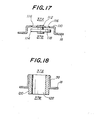
- Fig. 17 is shown a modification of the partition member 18 as shown in Fig. 1, wherein the partition member 18 is a hat-shaped body of a plate material 110 and a flat plate 114 is disposed in a recess portion of the plate material 110 through a pin 112 fixed to the center of the ceiling part of the plate material 110. Further, a plurality of small circular holes 116 are formed in the ceiling part around the pin 112 in correspondence with the flat plate 114.
- the upper liquid chamber 37A is communicated with the middle liquid chamber 37B through a restricted passage 118 defined between the ceiling part of the plate material 110 having holes 116 and the flat plate 114.
- Fig. 18 is shown another modification of the partition member 18 shown in Fig. 1, wherein a hollow cylindrical body 120 is fixed to the inner peripheral surface of that portion of the partition member 18 which forms the cylindrical hole 38. Therefore, the inside of the cylindrical body 120 defines a restricted passage 90.
- vibrations having a high frequency and a small amplitude can be absorbed by the liquid column resonance through the restricted passage 118 or 122.
- the vibration frequency to be absorbed can be adjusted by optionally changing the size of such a restricted passage.
- the invention is applicable to the vibration isolating devices having four or more small liquid chambers.
- a restricted passage having a largest sectional area among restricted passages communicating the liquid chambers with each other is disposed near the side of vibration source.
- the hollow chamber in the main vibration-absorbing body composed mainly of the elastomeric material is. filled with a vibration-damping liquid and divided into at least three liquid chambers by plural restricted passages, and a first restricted passage among these restricted passages has a diameter larger than that of the remaining restricted passages, so that vibrations over a wide frequency range can be damped effectively. Further, the size of the restricted passage can be adequately changed in accordance with the vibration frequency to be absorbed.
Abstract
Description
- This invention relates to a vibration isolating device for damping vibrations from vibration source.
- The vibration isolating device generally called as a rubber vibration isolator is used, for example, as an engine mount for automobile vehicles, whereby vibra-. tions from an internal-combustion engine are absorbed so as not to be transmitted to a vehicle chassis.
- As the vibration isolating device of this type,, there has been proposed a vibration isolating device comprising two vibration-damping liquid chambers separated by a partition member provided with a restricted-passage, in which vibrations from vibration source are absorbed by a flow resistance subjected to the liquid when the vibration is transmitted to the one chamber to thereby flow the liquid from the one chamber to the other through the restricted passage. In this device, not only the vibration transmitting force is lowered as far as possible at various vibration frequencies, but also the damping force is developed at a frequency range of 10-20 Hz corresponding to the vibration from the engine.
- In the conventional engine mount, however, it is very difficult to absorb vibrations of particular frequency other than the engine vibration. That is, when the vibration input to the engine mount is a high frequency, the amplitude is small to render the restricted passage into a clogged state, so that the pressure inside the liquid chamber rises to increase the dynamic spring constant. As a result, the vibration transmitting rate is undesirably raised to deteriorate the ride comfort on the vehicle.
- As a countermeasure for solving the latter problem, there has also been proposed a vibration isolating device capable of absorbing high-frequency vibrations, but it is not yet sufficient to damp the high-frequency vibrations. Therefore, it is strongly demanded to develop a vibration isolating device capable of damping vibrations at a wider frequency range.
- With the foregoing in mind, it is an object of the invention to provide a vibration isolating device which can effectively prevent the transmission of vibrations to a vehicle chassis by not only generating a damping force against a low frequency vibration but also suppressing a dynamic factor to not more than 1.5 times with the resonance of the damping liquid against vibrations of a higher frequency range.
- According to the invention, there is the provision of a vibration isolating device comprising a main vibration-absorbing body composed mainly of an elastomeric material and provided at its inside with a hollow chamber containing a vibration-damping liquid therein, and plural partition members each provided with a restricted passage therein to divide said hollow chamber into at least three small liquid chambers, one of said restricted passages having a sectional area larger than that of the other remaining restricted passages.
- The invention will be described with reference to the accompanying drawings, wherein:
- Fig. 1 is a sectional view of a first embodiment of the vibration isolating device according to the invention;
- Fig. 2 is an exploded perspective view of a lower partition member used in the vibration isolating device of Fig. 1;
- Figs. 3a and 3b are graphs showing dynamic factor and tan 6 with respect to frequency in the device of Fig. 1, respectively;
- Fig. 4 is a sectional view of a second embodiment of the vibration isolating device according to the invention;
- Fig. 5 is a graph showing a relation between frequency and dynamic factor in the device of Fig. 4;
- Figs. 6 to 8 are sectional views of third to fifth embodiments of the vibration isolating device according to the invention, respectively;
- Fig. 9 is graph showing a relation between frequency and dynamic factor in the devices of Figs. 6, 7 and 8;
- Figs. 10a and 10b are graphs showing dynamic factor and tan δ with respect to frequency in the device of Fig. 8, respectively;
- Figs. 11 to 14 are sectional views of sixth to ninth embodiments of the vibration isolating device according to the invention, respectively;
- Figs. 15 and 16 are graphs showing tan 6 and dynamic factor with respect to frequency in the device of Fig. 14, respectively; and
- Figs. 17 and 18 are sectional views of the other embodiments of the partition member used in the invention, respectively.
- Like parts are designated by like numerals throughout the different figures of the drawings.
- In Fig. 1 is sectionally shown a first embodiment of the vibration isolating device according to the invention. This vibration isolating device is used as an engine mount for automobile vehicle.
- The vibration isolating device comprises a
hollow bottom cylinder 10, to the inside of which at its axially middle position is clamped an outer peripheral portion of aring plate 12. Further, alower diaphragm 14 is clamped at its outer peripheral portion between thering plate 12 and a step portion 10A of thecylinder 10 formed just beneath thering plate 12 and forms anair chamber 16 together with abottom plate 10B of thecylinder 10. Thisair chamber 16 may be communicated with an exterior through a hole formed in thebottom plate 10B. - The upper end portion of the
bottom cylinder 10 is fixed to a lower end portion of ajoint cylinder 20 through anupper partition member 18. - The upper end portion of the
joint cylinder 20 is enlarged upward, to which is bonded arubber member 22 as a vibration-absorbing main body by vulcanization. In this case, other elastomeric materials may be used instead of therubber member 22. The upper end portion of therubber member 22 is bonded by vulcanization to abase plate 24 provided with afitting bolt 26. Thebase plate 24 is used for carrying an engine (not shown), wherein the engine is fixed to thebase plate 24 through thefitting bolt 26. - A
flange 28 is protruded outward from the lower end portion of thejoint cylinder 20 and provided withplural fitting bolts 30 for fixing a vehicle chassis (not shown). - A closed space is defined as a liquid chamber by the
bottom cylinder 10,lower diaphragm 14,joint cylinder 20,rubber member 22 andbase plate 24 and filled with a vibration-damping liquid such as water or the like. - The
upper partition member 18 divides the closed space into an upperliquid chamber 37A and a middleliquid chamber 37B. Both the liquid chambers are communicated with each other through acylindrical hole 38 formed in the center of thepartition member 18 as a restricted passage. - The
ring plate 12 clamped together with thelower diaphragm 14 to thebottom cylinder 10 serves as a lower partition member and comprises a central upheaved portion composed of acylindrical part 58 and aceiling part 60, which divides the closed space into the middleliquid chamber 37B and a lowerliquid chamber 37C. Thus, the closed space is divided into theupper liquid chamber 37A, middleliquid chamber 37B and lowerliquid chamber 37C by theupper partition member 18 and thelower partition member 12. - As shown in Fig. 2, the
ring plate 12 is formed by lapping and fixing twoplate materials plate material 56 is a hat-shaped body provided with thecylindrical part 58 and theceiling part 60 and made, for example, by deep drawing of a disc metal sheet. To a recess bottom of theplate material 56 is fixed theplate material 62 of an annular metal sheet provided at its outer peripheral portion with a ring-like depression 63. In this way, a restricted passage or anorifice 64 is formed between theplate material 56 and theplate material 62, and communicated with the middleliquid chamber 37B through anopening 66 formed in theceiling part 60 of theplate material 56 on the one hand and with thelower liquid chamber 37C through anopening 68 formed in theplate material 62 on the other hand. - In this illustrated embodiment, the
partition member 18 provided with thecylindrical hole 38 is disposed at a side of vibration source or near thebase plate 24. Further, theorifice 64 is small in the diameter and long in the axial length as compared with thecylindrical hole 38. (The axial length of theorifice 64 is more than 5 times the sectional area thereof.) - The operation of the vibration isolating device of Fig. 1 will be described below.
- The
flange 28 is mounted on the vehicle chassis and fixed thereto through thefitting bolts 30, while the engine for automobile vehicle is fixed to thebase plate 24 through thefitting bolt 26. - In the mounting of the engine, the dead weight of the engine is applied to the
base plate 24 to increase the pressure inside the upperliquid chamber 37A. Such an increase of the pressure is transmitted to the middleliquid chamber 37B through thecylindrical hole 38 and further to thelower liquid chamber 37C through theorifice 64, whereby thelower diaphragm 14 is displaced toward a direction of contracting theair chamber 16. - In the working of the engine, vibrations generated from the engine are transmitted to the device through the
base plate 24. Of course, therubber member 22 can absorb the vibration owing to its damping function based on the internal friction. - In case of a low vibration frequency, for example, when vibrations have a frequency range of 5-20 Hz and an amplitude of ±0.5-1.0 mm, the vibration-damping effect is further enhanced by the viscosity resistance caused in the flowing of the liquid through the restricted passage having a long axial length and a small sectional area or the
orifice 64. In this case, thecylindrical hole 38 hardly develops the vibration-damping action because it has a large sectional area. - Particularly, the vibration-damping effect against vibrations of low frequency and large amplitude is large because the
orifice 64 is a C-shaped, long restricted passage defined between theplate material 56 and theplate material 62. Moreover, the axial length of theorifice 64 may optionally be adjusted by changing a relative angle between theopenings plate material 62 to theplate material 56 by welding or the like. - In case of a high vibration frequency, for example, when vibrations have a frequency range of more than 20 Hz and a slight amplitude, there is a possibility that the
orifice 64 becomes a clogged state. In this case, thecylindrical hole 38 does not produce the clogging owing to its large sectional area, so that the liquid inside the device produces a liquid column resonance, whereby specified high frequency vibrations are appropriately absorbed in accordance with the shape and size of thecylindrical hole 38. - In the illustrated embodiment, the
bottom cylinder 10 may be made from a metal or a flexible elastomer. As the bottom cylinder is rendered flexible, the resonance frequency produced in thecylindrical hole 38 and theorifice 64 becomes lower, from which a proper resonance frequency can be selected. - The size of the
cylindrical hole 38 in Fig. 1 will be described below. - Assuming that the volume of the upper
liquid chamber 37A is changed by A cm3 when therubber member 22 is bent by 1 cm under the application of the engine dead weight, if the upperliquid chamber 37A has an effective diameter of Do cm and an effective sectional area of π (Do/2)2 and thecylindrical hole 38 has a length of L cm and a diameter of D cm, it is required to satisfy D/Do of not less than 1/3 and L/D2 of not more than 1/3. - When D/Do is less than 1/3, the
cylindrical hole 38 is apt to produce the clogging at the high vibration frequency. Further: when L/D2 is more than 1/3, the reduction of dynamic factor occurs at low vibration frequency. The term "dynamic factor" used herein means a ratio of dynamic spring constant to static spring constant. - When the size of the
cylindrical hole 38 satisfies the above requirements, a low dynamic factor can be obtained at a high frequency range of 100-200 Hz. - Fig. 3a shows a relation between the frequency and the dynamic factor in the device of Fig. 1, and Fig. 3b shows a relation between the frequency and the loss factor (tan 6) in the same device, from which it is understood that a large vibration-damping force can be obtained at an arbitrary frequency.
- In Fig. 4 is shown a second embodiment of the vibration isolating device according to the invention, which is a modification of the device shown in Fig. 1. That is, the ring plate or
partition member 18 is provided with anopening 18A instead of thecylindrical hole 38. Further, arubber member 70 having a hardness larger than that of therubber member 22 is secured at its one end to an upper surface of the base blate 24 and at the other end to afitting plate 71 for an engine provided with thefitting bolt 26. Moreover, thebottom plate 10B is provided at its outer bottom surface with a fitting bolt 30'. - In the embodiment of Fig. 4, the building-up of the dynamic factor in the liquid column resonance can be made low as shown in Fig. 5. Moreover, the
rubber member 70 may also be disposed at the side of thebottom cylinder 10. - In Fig. 6 is shown a third embodiment of the vibration isolating device according to the invention, which is also a modification of the device shown in Fig. 1. That is, the
partition member 18 is provided with anopening 18A instead of thecylindrical hole 38. Further, theplate material 56 constituting a part of thepartition member 12 is provided at the center of theceiling portion 60 with acircular hole 60A for receiving amovable disc body 70. Thismovable disc body 70 is provided at its outer peripheral edge with aflange 74 of J-shape in section and is possible to move in up and down direction by a slight amount (about 0.1-0.05 mm) with respect to the peripheral edge.of thecircular hole 60A, whereby the pressure increase can be suppressed under high frequency vibrations. The fitting position of themovable disc body 72 is not restricted as far as it is existent between the middleliquid chamber 37B and thelower liquid chamber 37C. - In Fig. 7 is shown a fourth embodiment of the vibration isolating device according to the invention, which is a further modification of the device shown in Fig. 4. In this case, the
partition member 12 is formed by clamping anannular plate 56A between thebottom cylinder 10 and thebottom plate 10B thereof and inserting theplate material 56 provided at its outer peripheral edge with aflange 74 of D-shape in section into a hole of theannular plate 56A. Thus, it is possible to slightly move theplate material 56 in up and down direction with respect to theannular plate 56A and hence thebottom cylinder 10, whereby there can be obtained the same effect as in the device of Fig. 6. - In Fig. 8 is shown a fifth embodiment of the vibration isolating device according to the invention, which is a modification of the device shown in Fig. 6. That is, a
rubber membrane 76 is fixed to a peripheral edge of thecircular hole 60A formed in the central portion of theceiling portion 60 instead of themovable disc body 72. In this case, wire cords or the like are embedded in therubber membrane 76 to restrict the moving quantity of themembrane 76. Thus, therubber membrane 76 plays the same role as themovable disc body 72. - Fig. 9 shows the relation between the frequency and the dynamic factor in the devices of Figs.6, 7 and 8.
- Figs. 10a and 10b show experimental results in the device of Fig. 8. In this experiment, the upper
liquid chamber 37A is filled with 70 cc of an antifreezing liquid, each of the middle and lowerliquid chambers air chamber 16 is filled with 70 cc of air, the rubber member has a dynamic spring constant of 120 kgf/cm and tan δ (loss factor) of 0.1, and thebottom cylinder 10 is an elastomer having the same volume elasticity as that of the rubber member and a dynamic spring constant of 220 kgf/cm. Further, theopening 18A has a diameter of 4 cm and a length of 0.5 cm and theorifice 64 has a diameter of 0.8 cm and a length of 5.0 cm. In the device having the above dimensions, tan 6 can be made large against vibrations having a frequency of 10-15 Hz and an amplitude of ±1 mm as shown in Figs. 10a and 10b. Further, since the device has therubber membrane 76 as a movable member, there is no building-up of the dynamic spring constant against vibrations having a frequency of about 10 Hz and a small amplitude of about ±0.05 mm and tan δ is not produced at a frequency of about 10 Hz. And also, the dynamic spring constant can considerably be reduced at a frequency of 100-180 Hz due to the presence of theopening 18A. - In Fig. 11 is shown a sixth embodiment of the vibration isolating device according to the invention, which is also a modification of Fig. 4. In this case, a
ring member 78 is embedded in therubber member 22 to adjust the elastic force of therubber member 22. - In Fig. 12 is shown a seventh embodiment of the vibration isolating device according to the invention, wherein a regulating
plate 80 is integrally fixed to the top surface of thebase plate 24 and extends outward therefrom. The outer peripheral portion of the regulatingplate 80 is bent downward at a right angle to form aregulation part 82. Anannular rubber stopper 84 is secured to the inner surface of theregulation part 82 and is opposite to arubber member 86 fixed to the outer peripheral surface of thejoint cylinder 20. In this embodiment, therefore, the movement of thebase plate 24 in the lateral direction can be restricted. - In Fig. 13 is shown an eighth embodiment of the vibration isolating device according to the invention, wherein the
partition member 18 is formed by lapping and fixing twoplate materials ring plate 12 to form anorifice 88. In this case, theorifice 88 is large in the sectional area and short in the axial length as compared with theorifice 64 of thering plate 12. - In Fig. 14 is shown a ninth embodiment of the vibration isolating device according to the invention, wherein the
ring plate 12 composed of the twoplate material ring plate member 12A and thelower diaphragm 14 in the middle portion of thebottom cylinder 10 and also thepartition member 18 composed of twoplate materials ring plate member 18A and thejoint cylinder 20. Further, acylindrical diaphragm 32 is bonded by vulcanization at its upper and lower end portions to thering plate members air chamber 34 is formed between thecylindrical diaphragm 32 and the bottom cylinder 10-. In this case theair chamber 34 may be communicated with an exterior through a hole formed in thebottom cylinder 10. - Fig. 15 shows the relation between the frequency and the loss factor (tan 6) of the device shown in Fig. 14, wherein a
characteristic curve 100 is the case against vibrations having a low frequency and a large amplitude and acharacteristic curve 102 is the case against vibrations having a high frequency and a small amplitude. Furthermore, Fig. 16 shows the relation between the frequency and the dynamic factor of the device shown in Fig. 14, wherein acharacteristic curve 104 is the case against vibrations having a low- frequency and a large amplitude and acharacteristic curve 106 is the case against vibrations having a high frequency and a small amplitude. - In Figs. 15 and 16, the
characteristics orifice 64, while thecharacteristics orifice 88. A characteristic 108 shown by dotted lines in Fig. 16 shows the relation between the frequency and the dynamic factor when only theorifice 64 is provided in the device of Fig. 14. - In Fig. 17 is shown a modification of the
partition member 18 as shown in Fig. 1, wherein thepartition member 18 is a hat-shaped body of a plate material 110 and aflat plate 114 is disposed in a recess portion of the plate material 110 through apin 112 fixed to the center of the ceiling part of the plate material 110. Further, a plurality of smallcircular holes 116 are formed in the ceiling part around thepin 112 in correspondence with theflat plate 114. Thus, the upperliquid chamber 37A is communicated with the middleliquid chamber 37B through arestricted passage 118 defined between the ceiling part of the plate material 110 havingholes 116 and theflat plate 114. - In Fig. 18 is shown another modification of the
partition member 18 shown in Fig. 1, wherein a hollowcylindrical body 120 is fixed to the inner peripheral surface of that portion of thepartition member 18 which forms thecylindrical hole 38. Therefore, the inside of thecylindrical body 120 defines a restrictedpassage 90. - In the embodiments of Figs. 17 and 18, vibrations having a high frequency and a small amplitude can be absorbed by the liquid column resonance through the restricted
passage - Although all of the above illustrated embodiments have been described with respect to the small three liquid chambers divided by two partition members, the invention is applicable to the vibration isolating devices having four or more small liquid chambers. In the latter case, a restricted passage having a largest sectional area among restricted passages communicating the liquid chambers with each other is disposed near the side of vibration source.
- As mentioned above, according to the invention, the hollow chamber in the main vibration-absorbing body composed mainly of the elastomeric material is. filled with a vibration-damping liquid and divided into at least three liquid chambers by plural restricted passages, and a first restricted passage among these restricted passages has a diameter larger than that of the remaining restricted passages, so that vibrations over a wide frequency range can be damped effectively. Further, the size of the restricted passage can be adequately changed in accordance with the vibration frequency to be absorbed.
Claims (3)
Applications Claiming Priority (4)
| Application Number | Priority Date | Filing Date | Title |
|---|---|---|---|
| JP24890883A JPS60139941A (en) | 1983-12-28 | 1983-12-28 | Vibration isolator |
| JP248908/83 | 1983-12-28 | ||
| JP59121530A JPH061094B2 (en) | 1984-06-13 | 1984-06-13 | Anti-vibration device |
| JP121530/84 | 1984-06-13 |
Publications (3)
| Publication Number | Publication Date |
|---|---|
| EP0147242A2 true EP0147242A2 (en) | 1985-07-03 |
| EP0147242A3 EP0147242A3 (en) | 1986-05-07 |
| EP0147242B1 EP0147242B1 (en) | 1991-09-25 |
Family
ID=26458876
Family Applications (1)
| Application Number | Title | Priority Date | Filing Date |
|---|---|---|---|
| EP84309150A Expired - Lifetime EP0147242B1 (en) | 1983-12-28 | 1984-12-28 | Vibration isolating devices |
Country Status (3)
| Country | Link |
|---|---|
| US (1) | US4630808A (en) |
| EP (1) | EP0147242B1 (en) |
| DE (1) | DE3485117D1 (en) |
Cited By (21)
| Publication number | Priority date | Publication date | Assignee | Title |
|---|---|---|---|---|
| FR2559864A1 (en) * | 1984-02-21 | 1985-08-23 | Honda Motor Co Ltd | VIBRATION ISOLATOR |
| EP0173273A2 (en) * | 1984-08-27 | 1986-03-05 | Bridgestone Corporation | Vibration isolating apparatus |
| EP0174184A2 (en) * | 1984-09-07 | 1986-03-12 | Bridgestone Corporation | Vibration isolating apparatus |
| FR2589208A1 (en) * | 1985-10-28 | 1987-04-30 | Hutchinson Sa | IMPROVEMENTS ON HYDRAULIC ANTIVIBRATORY SUPPORTS |
| DE3700589A1 (en) * | 1986-01-10 | 1987-07-16 | Bridgestone Corp | VIBRATION DAMPER |
| FR2596838A1 (en) * | 1986-04-05 | 1987-10-09 | Freudenberg Carl | Engine bearing with hydraulic damping |
| FR2599451A1 (en) * | 1986-05-27 | 1987-12-04 | Freudenberg Carl | ENGINE SUPPORT |
| EP0259054A2 (en) * | 1986-09-05 | 1988-03-09 | Lord Corporation | Vibration attenuator using electrorheological and other fluids |
| EP0276673A1 (en) * | 1987-01-21 | 1988-08-03 | ITT Industrie Riunite SpA | Elastic antivibration support with hydraulic damping, especially for a piston engine |
| US4793600A (en) * | 1986-03-14 | 1988-12-27 | Bridgestone Corporation | Vibration isolating apparatus |
| EP0297174A2 (en) * | 1987-07-02 | 1989-01-04 | Firma Carl Freudenberg | Engine mounting |
| FR2617930A1 (en) * | 1987-07-07 | 1989-01-13 | Peugeot | HYDROELASTIC SUPPORT, IN PARTICULAR FOR PROVIDING THE SUSPENSION OF AN ENGINE IN A VEHICLE |
| US4856750A (en) * | 1987-04-13 | 1989-08-15 | Automobiles Peugeot | Hydroelastic support, in particular for the suspension of a vehicle engine |
| US4861006A (en) * | 1986-09-16 | 1989-08-29 | Bridgestone Corporation | Anti-vibration apparatus |
| US4871150A (en) * | 1987-01-20 | 1989-10-03 | Automobiles Peugeot | Elastically yieldable support in particular for the suspension of a vehicle engine |
| EP0384966A2 (en) * | 1989-03-01 | 1990-09-05 | Firma Carl Freudenberg | Engine mounting |
| EP0390670A1 (en) * | 1989-03-28 | 1990-10-03 | Automobiles Peugeot | Modified damping device with automatically variable damping |
| FR2663706A1 (en) * | 1990-06-26 | 1991-12-27 | Tokai Rubber Ind Ltd | Elastic mount filled with a fluid and including means for controlling the elastic deformation of one or more diaphragms defining one or more equilibrium chambers |
| US5078369A (en) * | 1988-03-08 | 1992-01-07 | Automobiles Peugeot | Elastically yieldable connection with a hydraulic stiffening |
| DE4123892A1 (en) * | 1990-07-19 | 1992-02-20 | Tokai Rubber Ind Ltd | ELASTIC STORAGE WITH A FLUID FILLING |
| FR2702021A1 (en) * | 1993-02-26 | 1994-09-02 | Peugeot | Modular hydroelastic mount |
Families Citing this family (15)
| Publication number | Priority date | Publication date | Assignee | Title |
|---|---|---|---|---|
| DE3526686A1 (en) * | 1985-07-25 | 1987-02-05 | Metzeler Kautschuk | TWO-CHAMBER ENGINE MOUNT WITH HYDRAULIC DAMPING |
| IT1185942B (en) * | 1985-09-18 | 1987-11-18 | G A Soc Applic Gomma Antivibra | SUPPORT FOR THE ELASTIC SUSPENSION OF A MOTOR OF A VEHICLE COMPARED TO THE BODYWORK OF THE SAME |
| US4721292A (en) * | 1986-07-24 | 1988-01-26 | Tokai Rubber Industries, Ltd. | Fluid-filled elastic mounting structure |
| JPS63176844A (en) * | 1986-09-16 | 1988-07-21 | Bridgestone Corp | Vibration-proof bush |
| US4795140A (en) * | 1986-12-30 | 1989-01-03 | Bridgestone Corporation | Vibration isolating apparatus |
| JPS6479442A (en) * | 1987-09-21 | 1989-03-24 | Tokai Rubber Ind Ltd | Fluid-sealed type mounting device |
| US4925162A (en) * | 1988-06-17 | 1990-05-15 | Bridgestone Corporation | Vibration isolating devices |
| DE4322958C2 (en) * | 1993-07-09 | 1996-11-21 | Freudenberg Carl Fa | Active control element |
| US5402317A (en) * | 1993-12-29 | 1995-03-28 | The United States Of America As Represented By The Secretary Of The Navy | Method and means for isolating equipment from shock loads |
| JP4261038B2 (en) * | 2000-08-24 | 2009-04-30 | 東洋ゴム工業株式会社 | Controlled liquid filled vibration isolator |
| DE102005006557A1 (en) * | 2005-02-11 | 2006-08-31 | Zf Friedrichshafen Ag | Bump stop for a door or flap of a motor vehicle |
| DE102010030626A1 (en) * | 2010-06-29 | 2011-12-29 | Robert Bosch Gmbh | Pulsation damper element for a fluid pump and associated fluid pump |
| EP3070365B1 (en) * | 2013-11-11 | 2018-12-19 | Bridgestone Corporation | Vibration damping device |
| JP6384986B2 (en) * | 2014-04-24 | 2018-09-05 | 株式会社ブリヂストン | Vibration isolator |
| US10145443B2 (en) | 2015-01-26 | 2018-12-04 | Itt Manufacturing Enterprises Llc | Compliant elastomeric shock absorbing apparatus |
Citations (10)
| Publication number | Priority date | Publication date | Assignee | Title |
|---|---|---|---|---|
| FR2415241A1 (en) * | 1978-01-24 | 1979-08-17 | Audi Ag | HYDRAULIC CUSHIONED RUBBER MOUNTING BRACKET |
| GB2041485A (en) * | 1979-02-10 | 1980-09-10 | Freudenberg C Kg | Fluid-damped elastomeric mountings |
| FR2472116A1 (en) * | 1979-12-13 | 1981-06-26 | Continental Gummi Werke Ag | ELASTIC BEARING |
| JPS5694043A (en) * | 1979-12-26 | 1981-07-30 | Toyoda Gosei Co Ltd | Liquid encapsulation vibration preventer |
| JPS5776340A (en) * | 1980-10-29 | 1982-05-13 | Toyoda Gosei Co Ltd | Liquid sealed-in vibration-proof apparatus |
| GB2087511A (en) * | 1980-11-18 | 1982-05-26 | Imp Clevite Inc | Self-leveling fluid damped elastomeric spring unit |
| DE8119912U1 (en) * | 1981-07-08 | 1982-07-08 | Boge Gmbh, 5208 Eitorf | Elastomer bearings, especially single-chamber rubber bearings with hydraulic damping |
| DE3142673A1 (en) * | 1981-10-28 | 1983-05-05 | Continental Gummi-Werke Ag, 3000 Hannover | Elastic mount, in particular for the engine in motor vehicles |
| DE3207889A1 (en) * | 1982-03-05 | 1983-09-15 | Continental Gummi-Werke Ag, 3000 Hannover | Elastic mount with hydraulic damping |
| JPS59190531A (en) * | 1983-04-08 | 1984-10-29 | Honda Motor Co Ltd | Engine mount with fluid inside |
Family Cites Families (4)
| Publication number | Priority date | Publication date | Assignee | Title |
|---|---|---|---|---|
| DE2962362D1 (en) * | 1978-12-07 | 1982-04-29 | Peugeot | Elastic mounting, particularly for the suspension of a vehicle motor |
| US4483521A (en) * | 1981-07-01 | 1984-11-20 | Nissan Motor Company, Limited | Rubber and fluid type vibration damper |
| DE3225700C1 (en) * | 1982-07-09 | 1983-11-17 | Fa. Carl Freudenberg, 6940 Weinheim | Elastic rubber bearing |
| US4588173A (en) * | 1983-11-23 | 1986-05-13 | General Motors Corporation | Hydraulic-elastomeric mount |
-
1984
- 1984-12-28 DE DE8484309150T patent/DE3485117D1/en not_active Expired - Fee Related
- 1984-12-28 US US06/687,337 patent/US4630808A/en not_active Expired - Lifetime
- 1984-12-28 EP EP84309150A patent/EP0147242B1/en not_active Expired - Lifetime
Patent Citations (10)
| Publication number | Priority date | Publication date | Assignee | Title |
|---|---|---|---|---|
| FR2415241A1 (en) * | 1978-01-24 | 1979-08-17 | Audi Ag | HYDRAULIC CUSHIONED RUBBER MOUNTING BRACKET |
| GB2041485A (en) * | 1979-02-10 | 1980-09-10 | Freudenberg C Kg | Fluid-damped elastomeric mountings |
| FR2472116A1 (en) * | 1979-12-13 | 1981-06-26 | Continental Gummi Werke Ag | ELASTIC BEARING |
| JPS5694043A (en) * | 1979-12-26 | 1981-07-30 | Toyoda Gosei Co Ltd | Liquid encapsulation vibration preventer |
| JPS5776340A (en) * | 1980-10-29 | 1982-05-13 | Toyoda Gosei Co Ltd | Liquid sealed-in vibration-proof apparatus |
| GB2087511A (en) * | 1980-11-18 | 1982-05-26 | Imp Clevite Inc | Self-leveling fluid damped elastomeric spring unit |
| DE8119912U1 (en) * | 1981-07-08 | 1982-07-08 | Boge Gmbh, 5208 Eitorf | Elastomer bearings, especially single-chamber rubber bearings with hydraulic damping |
| DE3142673A1 (en) * | 1981-10-28 | 1983-05-05 | Continental Gummi-Werke Ag, 3000 Hannover | Elastic mount, in particular for the engine in motor vehicles |
| DE3207889A1 (en) * | 1982-03-05 | 1983-09-15 | Continental Gummi-Werke Ag, 3000 Hannover | Elastic mount with hydraulic damping |
| JPS59190531A (en) * | 1983-04-08 | 1984-10-29 | Honda Motor Co Ltd | Engine mount with fluid inside |
Non-Patent Citations (3)
| Title |
|---|
| PATENTS ABSTRACTS OF JAPAN, vol. 5, no. 170 (M-94) [842], 29th October 1981; & JP - A - 56 94 043 (TOYODA GOSEI K.K.) 30-07-1981 * |
| PATENTS ABSTRACTS OF JAPAN, vol. 6, no. 161 (M-151) [1039], 24th August 1982; & JP - A - 57 76 340 (TOYODA GOSEI K.K.) 13-05-1982 * |
| PATENTS ABSTRACTS OF JAPAN, vol. 9, no. 55 (M-362) [1778], 9th March 1985; & JP - A - 59 190 531 (HONDA GIKEN KOGYO K.K.) 29-10-1984 * |
Cited By (33)
| Publication number | Priority date | Publication date | Assignee | Title |
|---|---|---|---|---|
| FR2559864A1 (en) * | 1984-02-21 | 1985-08-23 | Honda Motor Co Ltd | VIBRATION ISOLATOR |
| EP0173273A3 (en) * | 1984-08-27 | 1988-03-30 | Bridgestone Corporation | Vibration isolating apparatus |
| EP0173273A2 (en) * | 1984-08-27 | 1986-03-05 | Bridgestone Corporation | Vibration isolating apparatus |
| EP0174184A2 (en) * | 1984-09-07 | 1986-03-12 | Bridgestone Corporation | Vibration isolating apparatus |
| EP0174184A3 (en) * | 1984-09-07 | 1986-05-14 | Bridgestone Corporation | Vibration isolating apparatus |
| US4802658A (en) * | 1984-09-07 | 1989-02-07 | Bridgestone Corporation | Vibration isolating apparatus |
| EP0225227A1 (en) * | 1985-10-28 | 1987-06-10 | Hutchinson | Modifications of hydraulic anti-vibration mountings |
| FR2589208A1 (en) * | 1985-10-28 | 1987-04-30 | Hutchinson Sa | IMPROVEMENTS ON HYDRAULIC ANTIVIBRATORY SUPPORTS |
| DE3700589A1 (en) * | 1986-01-10 | 1987-07-16 | Bridgestone Corp | VIBRATION DAMPER |
| US4793600A (en) * | 1986-03-14 | 1988-12-27 | Bridgestone Corporation | Vibration isolating apparatus |
| FR2596838A1 (en) * | 1986-04-05 | 1987-10-09 | Freudenberg Carl | Engine bearing with hydraulic damping |
| US4971300A (en) * | 1986-04-05 | 1990-11-20 | Firma Carl Freudenberg | Motor mount having improved hydraulic damping |
| FR2599451A1 (en) * | 1986-05-27 | 1987-12-04 | Freudenberg Carl | ENGINE SUPPORT |
| EP0259054A2 (en) * | 1986-09-05 | 1988-03-09 | Lord Corporation | Vibration attenuator using electrorheological and other fluids |
| EP0259054A3 (en) * | 1986-09-05 | 1988-09-21 | Lord Corporation | Vibration attenuator using electrorheological and other fluids |
| US4973031A (en) * | 1986-09-16 | 1990-11-27 | Bridgestone Corporation | Anti-vibration apparatus |
| US4861006A (en) * | 1986-09-16 | 1989-08-29 | Bridgestone Corporation | Anti-vibration apparatus |
| US4871150A (en) * | 1987-01-20 | 1989-10-03 | Automobiles Peugeot | Elastically yieldable support in particular for the suspension of a vehicle engine |
| EP0276673A1 (en) * | 1987-01-21 | 1988-08-03 | ITT Industrie Riunite SpA | Elastic antivibration support with hydraulic damping, especially for a piston engine |
| US4856750A (en) * | 1987-04-13 | 1989-08-15 | Automobiles Peugeot | Hydroelastic support, in particular for the suspension of a vehicle engine |
| EP0297174A3 (en) * | 1987-07-02 | 1989-06-28 | Firma Carl Freudenberg | Engine mounting |
| DE3721811A1 (en) * | 1987-07-02 | 1989-01-12 | Freudenberg Carl Fa | ENGINE MOUNT |
| EP0297174A2 (en) * | 1987-07-02 | 1989-01-04 | Firma Carl Freudenberg | Engine mounting |
| FR2617930A1 (en) * | 1987-07-07 | 1989-01-13 | Peugeot | HYDROELASTIC SUPPORT, IN PARTICULAR FOR PROVIDING THE SUSPENSION OF AN ENGINE IN A VEHICLE |
| US4893797A (en) * | 1987-07-07 | 1990-01-16 | Automobiles Peugeot | Hydroelastic support, in particular for the suspension of a motor in a vehicle |
| US5078369A (en) * | 1988-03-08 | 1992-01-07 | Automobiles Peugeot | Elastically yieldable connection with a hydraulic stiffening |
| EP0384966A3 (en) * | 1989-03-01 | 1990-11-14 | Firma Carl Freudenberg | Engine mounting |
| EP0384966A2 (en) * | 1989-03-01 | 1990-09-05 | Firma Carl Freudenberg | Engine mounting |
| EP0390670A1 (en) * | 1989-03-28 | 1990-10-03 | Automobiles Peugeot | Modified damping device with automatically variable damping |
| FR2645079A1 (en) * | 1989-03-28 | 1990-10-05 | Peugeot | PERFECTED AUTOMATIC VARIABLE DAMPER DEVICE |
| FR2663706A1 (en) * | 1990-06-26 | 1991-12-27 | Tokai Rubber Ind Ltd | Elastic mount filled with a fluid and including means for controlling the elastic deformation of one or more diaphragms defining one or more equilibrium chambers |
| DE4123892A1 (en) * | 1990-07-19 | 1992-02-20 | Tokai Rubber Ind Ltd | ELASTIC STORAGE WITH A FLUID FILLING |
| FR2702021A1 (en) * | 1993-02-26 | 1994-09-02 | Peugeot | Modular hydroelastic mount |
Also Published As
| Publication number | Publication date |
|---|---|
| EP0147242A3 (en) | 1986-05-07 |
| EP0147242B1 (en) | 1991-09-25 |
| US4630808A (en) | 1986-12-23 |
| DE3485117D1 (en) | 1991-10-31 |
Similar Documents
| Publication | Publication Date | Title |
|---|---|---|
| EP0147242A2 (en) | Vibration isolating devices | |
| JP2977796B2 (en) | Fluid-filled elastic vibration damping device | |
| US4660812A (en) | Vibration isolating apparatus | |
| US4773634A (en) | Hydraulically damped elastic motor unit | |
| US4595183A (en) | Vibration isolating device | |
| US7232118B2 (en) | Fluid filled vibration damping device | |
| US5094433A (en) | Vibration isolating device | |
| JP3049105B2 (en) | Bush type vibration damping device and bush type liquid filling vibration damping device | |
| EP0065298A2 (en) | Engine mount device | |
| EP0133588A2 (en) | Vibration isolating device and system | |
| US7216858B2 (en) | Fluid-filled vibration damping device | |
| US5058866A (en) | Hydraulically damped mount | |
| EP0523896B1 (en) | Vibration isolating apparatus | |
| JPH05196086A (en) | Elastic engine mount | |
| US4850578A (en) | Fluid-filled elastic mount for damping a wide frequency range of vibrations | |
| EP0174184B1 (en) | Vibration isolating apparatus | |
| US4946147A (en) | Fluid-filled elastic mounting structure having orifices | |
| JP4301189B2 (en) | Fluid filled vibration isolator | |
| JP4075066B2 (en) | Fluid filled engine mount | |
| JPS63266242A (en) | Fluid-sealed type mount device | |
| JPS612936A (en) | Vibro-isolator | |
| JPS61197836A (en) | Vibration preventing device | |
| JPH08135726A (en) | Vibration control device | |
| JPH0434018B2 (en) | ||
| EP0326665A1 (en) | Vibration damping device |
Legal Events
| Date | Code | Title | Description |
|---|---|---|---|
| PUAI | Public reference made under article 153(3) epc to a published international application that has entered the european phase |
Free format text: ORIGINAL CODE: 0009012 |
|
| AK | Designated contracting states |
Designated state(s): DE FR GB IT |
|
| PUAL | Search report despatched |
Free format text: ORIGINAL CODE: 0009013 |
|
| AK | Designated contracting states |
Kind code of ref document: A3 Designated state(s): DE FR GB IT |
|
| 17P | Request for examination filed |
Effective date: 19860709 |
|
| 17Q | First examination report despatched |
Effective date: 19870805 |
|
| GRAA | (expected) grant |
Free format text: ORIGINAL CODE: 0009210 |
|
| AK | Designated contracting states |
Kind code of ref document: B1 Designated state(s): DE FR GB IT |
|
| PG25 | Lapsed in a contracting state [announced via postgrant information from national office to epo] |
Ref country code: IT Free format text: LAPSE BECAUSE OF FAILURE TO SUBMIT A TRANSLATION OF THE DESCRIPTION OR TO PAY THE FEE WITHIN THE PRESCRIBED TIME-LIMIT;WARNING: LAPSES OF ITALIAN PATENTS WITH EFFECTIVE DATE BEFORE 2007 MAY HAVE OCCURRED AT ANY TIME BEFORE 2007. THE CORRECT EFFECTIVE DATE MAY BE DIFFERENT FROM THE ONE RECORDED. Effective date: 19910925 |
|
| REF | Corresponds to: |
Ref document number: 3485117 Country of ref document: DE Date of ref document: 19911031 |
|
| EN | Fr: translation not filed | ||
| PG25 | Lapsed in a contracting state [announced via postgrant information from national office to epo] |
Ref country code: FR Effective date: 19920214 |
|
| PLBE | No opposition filed within time limit |
Free format text: ORIGINAL CODE: 0009261 |
|
| STAA | Information on the status of an ep patent application or granted ep patent |
Free format text: STATUS: NO OPPOSITION FILED WITHIN TIME LIMIT |
|
| 26N | No opposition filed | ||
| REG | Reference to a national code |
Ref country code: FR Ref legal event code: ST |
|
| REG | Reference to a national code |
Ref country code: GB Ref legal event code: IF02 |
|
| PGFP | Annual fee paid to national office [announced via postgrant information from national office to epo] |
Ref country code: GB Payment date: 20021224 Year of fee payment: 19 |
|
| PGFP | Annual fee paid to national office [announced via postgrant information from national office to epo] |
Ref country code: DE Payment date: 20030109 Year of fee payment: 19 |
|
| PG25 | Lapsed in a contracting state [announced via postgrant information from national office to epo] |
Ref country code: GB Free format text: LAPSE BECAUSE OF NON-PAYMENT OF DUE FEES Effective date: 20031228 |
|
| PG25 | Lapsed in a contracting state [announced via postgrant information from national office to epo] |
Ref country code: DE Free format text: LAPSE BECAUSE OF NON-PAYMENT OF DUE FEES Effective date: 20040701 |
|
| GBPC | Gb: european patent ceased through non-payment of renewal fee |
Effective date: 20031228 |