EP0146566B1 - Scheme for reducing transmission delay following collision of transmissions in communication networks - Google Patents
Scheme for reducing transmission delay following collision of transmissions in communication networks Download PDFInfo
- Publication number
- EP0146566B1 EP0146566B1 EP84901914A EP84901914A EP0146566B1 EP 0146566 B1 EP0146566 B1 EP 0146566B1 EP 84901914 A EP84901914 A EP 84901914A EP 84901914 A EP84901914 A EP 84901914A EP 0146566 B1 EP0146566 B1 EP 0146566B1
- Authority
- EP
- European Patent Office
- Prior art keywords
- time period
- medium
- determining
- backoff
- backoff time
- Prior art date
- Legal status (The legal status is an assumption and is not a legal conclusion. Google has not performed a legal analysis and makes no representation as to the accuracy of the status listed.)
- Expired
Links
Images


Classifications
-
- H—ELECTRICITY
- H04—ELECTRIC COMMUNICATION TECHNIQUE
- H04B—TRANSMISSION
- H04B15/00—Suppression or limitation of noise or interference
- H04B15/02—Reducing interference from electric apparatus by means located at or near the interfering apparatus
-
- H—ELECTRICITY
- H04—ELECTRIC COMMUNICATION TECHNIQUE
- H04L—TRANSMISSION OF DIGITAL INFORMATION, e.g. TELEGRAPHIC COMMUNICATION
- H04L12/00—Data switching networks
- H04L12/28—Data switching networks characterised by path configuration, e.g. LAN [Local Area Networks] or WAN [Wide Area Networks]
- H04L12/40—Bus networks
- H04L12/4013—Management of data rate on the bus
- H04L12/40136—Nodes adapting their rate to the physical link properties
-
- H—ELECTRICITY
- H04—ELECTRIC COMMUNICATION TECHNIQUE
- H04L—TRANSMISSION OF DIGITAL INFORMATION, e.g. TELEGRAPHIC COMMUNICATION
- H04L12/00—Data switching networks
- H04L12/28—Data switching networks characterised by path configuration, e.g. LAN [Local Area Networks] or WAN [Wide Area Networks]
- H04L12/40—Bus networks
- H04L12/407—Bus networks with decentralised control
- H04L12/413—Bus networks with decentralised control with random access, e.g. carrier-sense multiple-access with collision detection [CSMA-CD]
Definitions
- the invention relates to communication networks in general and the response to transmission collisions by contention protocol networks in particular.
- a communication network comprises a plurality of stations connected to a communication medium.
- Each station includes a communicating device ; for example, a processor, a mass storage device, or an input and output terminal, and circuitry for interconnecting the device with the medium.
- Communications through the medium follow a prescribed communication protocol.
- a protocol is a set of rules describing the circumstances under which a station may communicate through the medium, the format of the communications, the proper response to various eventualities that may occur during communications, and other matters that must be consistent from station to station in order for the various stations to be able to communicate with each other.
- CSMA/CD Carrier Sense Multiple Access with Collision Detection
- each station in the network follows a predetermined formula for determining how long it must wait before reattempting a transmission of a collided communication.
- the delay time is referred to as a backoff period. Timing of the backoff period begins when a station terminates a collision-producing transmission.
- the formula for computing the backoff period uses a random number multiple of a basic delay time period, referred to as a time slot, to determine the backoff period.
- the time slot is at least equal in duration to the network's collision window, which is the maximum time period during which any transmission is in danger of possibly colliding with another transmission.
- the random number is independently generated at each station, and hence the backoff period generally varies from station to station.
- a new random number is generated at each station following each collision, and hence the backoff period generally varies at each station from collision to collision. Nevertheless, the formula leads to an average period of time following a collision during which period no station will attempt to retransmit a collided communication.
- the time slot is a function of transmission propagation delays, which are determined by the physical parameters of the network.
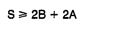
- the time slot, S has conventionally (e. g. «Computer » vol. 15, n° 8, August 1982, pp. 10-27) been computed as where A is the maximum interstation transmission propagation delay and where B is intrastation propagation delay.
- B is defined as the time elapsed from the point at which a first station initiates transmission to the point at which a second station can avoid initiating transmission in response to sensing transmission by the first station, assuming zero interstation transmission propagation delay on the medium.
- These propagation delays are inherent in the network. Therefore the minimum time slot, as conventionally determined, is presently immutable for a given network, and reduction of average transmission delay time is constrained thereby.
- the present invention is directed toward solving this prior art problem.
- the time slot for determining the backoff period is shortened to yield a shorter average delay time after collision.
- the backoff period is determined as a function, such as a multiple, of the time slot S wherein if timing of the backoff period is commenced only when the medium becomes quiescent following a collision, and communication is allowed to resume following expiration of the backoff period.
- Timing of the backoff period from the point at which the medium becomes quiescent enables the use of a shorter than conventional time slot, which in turn advantageously yields a shorter average collision backoff period.
- the network's communication throughput is thereby improved.
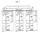
- the network comprises a plurality of communicating stations 90-92 connected for communication to a common communication medium, for example a coaxial cable bus 110.
- the coaxial cable bus 110 terminates at its ends in conventional terminators 94 and 95 that prevent reflections of communications from the ends of the bus 110.
- the stations 90-92 include communicating devices, for example processors and peripherals, referred to as hosts 100-102, respectively.
- the stations 90-92 are connected to the coaxial cable bus 110 via conventional transceivers 120-122, respectively.
- the hosts 100-102 are interfaced to the transceivers 120-122, respectively, for communication on the bus 110 by network interface units 130-132, respectively. Connection between the network interface units 130-132 and the transceivers 120-122 is via drop cables 140-142, respectively, such as twisted wire pairs.
- the hosts 100-102 communicate with each other by having messages transmitted to each other across the bus 110. Because use of the bus 110 is shared by the hosts 100-102, only one host can be effectively transmitting at any one time, and the hosts 100-102 contend for use of the bus 110. Contention resolution is a task of the network interface units 130-132, which operate in response to information about activities on the bus 110 supplied to them by the transceivers 120-122, respectively.
- the transceiver 120 is a conventional unit comprised of a transmitter 221, a receiver 222, and a collision detector 223.
- the transmitter 221 obtains messages from the network interface unit 130 and broadcasts, transmits, them on the coaxial cable bus 110.
- the receiver 222 receives all communications, messages, broadcast over the coaxial cable bus 110 and passes them on to the network interface unit 130.
- the collision detector 223 monitors activities on the bus 110 at the transceiver 120, for example transmissions of the transmitter 221 and receptions of the receiver 222, for purposes of determining the occurrence of collisions of two or more transmissions on the coaxial cable bus 110. When the collision detector 223 detects a collision, it sends a collision-indicative signal (COLL) to the network interface unit 130.
- COLL collision-indicative signal
- a representative network interface unit 130 is shown in Fig. 3.
- the network interface unit basically comprises a transmit control section 331, a transmit buffer memory 332, a receive control section 333, and a receive buffer memory 334.
- the receive control section 333 is a conventional circuit that receives messages from the receiver 222, checks the destination addresses of the messages to determine whether they are intended for the host 100, and if so, performs error checking on the messages, extracts data from the messages, transfers the data to the conventional receive buffer memory 334 for temporary storage, and controls the transfer of the data from the receive buffer memory 334 to the host 100, all in a conventional way.
- the receive control section 333 also conventionally generates a signal, commonly referred to as a carrier detect (CARR) signal, when it detects that the cable 110 is not quiescent i. e., when transmissions passing over the bus 110 and are being received by the receive control section 333 via the receiver 222.
- CARR carrier detect
- the receive control section 333 sends the carrier detect signal to the transmit control section 331.
- the transmit control section 331 extracts from the conventional transmit buffer memory 332 . destination addresses and data that have been stored therein by the host 100, and forms messages that include the data along with the address information designating the intended recipients of the messages and information suitable for checking the messages for errors, all in a conventional manner.
- the transmit control section 331 determines when a message may be broadcast through the network, and then sends the message to the transmitter 221 for transmission on the coaxial cable 110.
- the transmit control section 331 is shown in greater detail in Fig. 4.
- a transmit logic controller 405. controls the transmission of information from the transmit buffer memory 332 to the transmitter 221.
- the controller 405 provides the intelligence of the transmit control section 331.
- the transmit logic controller 405 may be, for example, a conventionally implemented sequential state machine, or a conventional microprogrammed controller.
- the operation of the transmit logic controller 405 is summarized in the logical flow diagram of Fig. 5. Figs. 4 and 5 should be referred to jointly in conjunction with the following discussion.
- the transmit logic controller 405 receives a signal telling it to transmit a message.
- This signal may be a signal generated by- the transmit buffer memory 332 indicating that the memory 332 is full and sent to the transmit logic controller 405 over a signal line labeled GO in Fig. 4.
- the GO line may be connected to the host 100 and the signal thereon may be generated by the host 100 after it has loaded the memory 332.
- the transmit logic controller 405 responds to the signal commanding it to transmit a message by checking whether the carrier detect signal is present.
- the transmit logic controller 405 does so by checking the output of a carrier detect circuit 402 which interfaces the carrier detect signal line, originating at the receive control section 333, to the transmit logic controller 405.
- the transmit logic controller 405 continues to monitor this signal.
- the transmit logic controller 405 initiates assembly of a message and transmission thereof to the cable 110, as indicated in block 502 of Fig. 5.
- the transmit logic controller 405 performs the activities summarized by block 502 by sending appropriately sequenced signals to : conventional code generators 410 to generate a message preamble and an error check code for the message ; a shift register 407 to retrieve address and data information from the transmit buffer memory 332 and to convert it into bit serial format ; and a multiplexer 409 to selectively couple the outputs of the code generators 410 and the shift register 407 to the drop cable 140 leading to the transmitter 221.
- an interface unit 131-132 may have already begun a transmission when the interface unit 130 found the coaxial cable bus 110 quiescent and began its own transmission. Conversely, an interface unit 131-132 may find the bus 110 to be quiescent and begin transmitting thereon after the interface unit 130 has commenced its transmission. In such situations the simultaneous transmissions collide on the medium 110 and become scrambled. Therefore the collided transmissions must be aborted and then reattempted.
- the collision i. e., the scrambled communications
- the collision detector 223 which reports it in the form of the collision detect signal to the transmit logic controller 405. Therefore, while the transmit logic controller 405 is undertaking the above-described activities, it also checks for the collision detect signal, as indicated in block 503 of Fig. 5.
- the transmit logic controller 405 does so by monitoring the output of a collision detect circuit 401 which interfaces the collision detect signal line, originating at the collision detector 223 of the transceiver 120, to the transmit logic controller 405.
- the transmit logic controller 405 continues with the transmission of the message and continues to check for the collision detect signal. If the transmission is completed without detection of a collision, as suggested by the block 504, the transmission is deemed a success, as indicated in block 505, and the transmit logic controller 405 then resumes waiting for the receipt of the next transmit message signal over the GO line.
- the transmit logic controller 405 re-. sponds thereto by causing message transmission to cease and a jam signal to be transmitted, as indicated in block 506.
- the transmit logic controller 405 does so by : sending signals to the shift register 407 and the code generators 410 to turn them off ; sending a signal to a jam generator 408 to cause it to generate a predetermined signal sequence ; and sending a signal to the multiplexer 409 to cause it to couple the output of the jam generator 408 to the drop line 140 leading to the transmitter 221.
- the signal sequence generated by the jam generator 408 is transmitted on the bus 110 ans reinforces there the collision, guaranteeing that the duration of the collision is sufficient to insure its detection by all transmitting stations in the network.
- the transmit logic controller 405 monitors the output of the carrier detect circuit 402, as indicated in block 507. While the carrier detect signal is present, the transmit logic control 405 continues to wait and to monitor further the presence of the signal. Only when the carrier detect signal ceases to be present, indicating that the cable 110 has become quiescent, does the transmit logic controller 105 begin to time a collision backoff period before reattempting transmission.
- the transmit logic controller 405 increments a collision counter 413 of a backoff compute circuit 403, to keep track of the number of times a failed attempt has been made to transmit the message. As indicated in block 509, the transmit logic controller 405 then checks the count of the collision counter 413 to determine whether the count has exceeded a predetermined threshold. If so, the transmit logic controller 405 generates an error signal, as indicated in block 510, and sends the error signal to the host 100 over the signal line designated as ERR in Fig. 4. If the threshold count has not been exceeded, the transmit logic controller 405 sends a signal to the backoff compute circuit 403 to cause it to compute a backoff value, as suggested by block 511.
- the backoff compute circuit 403 is a conventional circuit of the type used in contention protocol networks to compute a backoff value for use in collision avoidance.
- the backoff value designated as R
- R is a random number that is optionally modified, for example multiplied, by the number of collisions experienced by the transmitted message, which is the count of the collision counter 413.
- the value of R depends on the specific backoff algorithm employed, and various backoff algorithms are known to the art. But for purposes of collision avoidance, R is generally selected from any group of numbers the difference between any two of which is at least one. Conventionally, R is generally selected from non-negative pseudo-random integers.
- the backoff value R is utilized in determining the backoff period for which the transmit logic controller 405 must wait following a collision before attempting to retransmit the collided message.
- the compute backoff circuit 403 computes the backoff value and loads it Into backoff waiting circuit 411.
- the circuit 411 uses the backoff value to compute the backoff time period, and then times the backoff time period for the transmit logic controller 405.
- the transmit logic controller 405 After it has caused the backoff value to be computed at the block 511, the transmit logic controller 405 begins to monitor the output of the backoff waiting circuit 411 to determine whether the backoff time period has expired, as indicated in block 512.
- the backoff waiting circuit 411 includes a backoff counter register 404 and a backoff weighting circuit 406.
- the backoff counter register 404 stores the backoff value R that is received from the compute backoff circuit 403.
- the backoff weighting circuit 406 is a timing circuit that periodically decrements the value of the backoff counter 404.
- the time interval between decremen- tations is the time slot S of the network. Since it takes R time slot periods to decrement the count of the backoff counter 404 to zero, the backoff time period, designated as T, can be expressed as the product.
- the time slot S is a function of the network delay parameters B and A, as was mentioned previously.
- the delay parameter A is the inter- station, or medium, propagation delay, i. e.. the time it takes a signal transmitted on the coaxial cable bus 110 by a station 90 at one end of the cable 110 to traverse the bus 110 to a station 92 at the opposite end of the bus 110. Because stations may be connected to the utmost ends of the bus 110, A is generally taken to be the end-to-end propagation delay of the bus 110, which is a function of the length of the bus 110, as suggested by the pictorial representation of A in Fig. 1.
- the delay parameter B is the intrastation propagation delay.
- B is measured as the time from the point at which the transmit logic controller 405 of one station, for example the station 90, generates signals at its outputs to initiate a transmission, such as signals to the code generators 410 and the multiplexer 409 to generate and transfer out to the bus 110 the preamble of a message, to the point at which the transmit logic controller 405 of another station, for example the station 92, can avoid generating signals at its outputs that would initiate a transmission, in response to detecting the transmission of the one station 90, such as in response to receiving a carrier detect indication from the carrier detect circuit 402.
- the computation of the delay parameter B assumes no inter- station propagation delay, i. e., it excludes A.
- the parameter B includes the signal propagation delay from the transmit logic controller 405 of a station to the bus 110.
- the parameter B also includes the signal propagation delay from the bus 110 to the transmit logic controller 405 of a station and the time of response to the signal by the controller 405. Since the stations 90-92 are assumed to be substantially identical, except for the hosts 100-102, the parameter B may also be defined to include the signal propagation delay loop from the transmit logic controller 405 of a station, for example the station 90, to the bus 110 and back from the bus 110 to the transmit logic controller 405 of the same station 90, and the time of response to the signal by the controller 405, as suggested by the pictorial representation of B in Fig. 1.
- the parameter B may be seen to represent the propagation delay within a single station, even though the measurement of B is defined in terms of two stations.
- the lower bound for the time slot S is taken to be
- the average time period of transmission delay following a collision may be reduced in comparison to its conventional value without increasing the probability of occurrence of a further collision, providing that all other things remain equal. Since the average period of quiescence is reduced, network throughput capacity is improved.
- the value of S is selected such that and preferable such that and the backoff weighting circuit 406 is preadjusted to repeatedly time the selected time slot S.
- the backoff weighting circuit 406 Upon timing out the time slot S, the backoff weighting circuit 406 decrements the contents of the backoff counter 404 by one.
- the backoff weighting circuit 406 must time out the time slots a total of R times, for a total elapsed time period of T, before the backoff counter 404 is decremented to zero.
- the backoff weighting circuit 406 signals to the transmit logic controller 405 that the backoff period has elapsed. Following the expiration of the backoff time period, the transmit logic controller 405 is allowed to return its operation to the block 501 to reattempt transmission of the collided message.
Landscapes
- Engineering & Computer Science (AREA)
- Computer Networks & Wireless Communication (AREA)
- Signal Processing (AREA)
- Quality & Reliability (AREA)
- Small-Scale Networks (AREA)
- Optical Communication System (AREA)
Abstract
Description
- The invention relates to communication networks in general and the response to transmission collisions by contention protocol networks in particular.
- A communication network comprises a plurality of stations connected to a communication medium. Each station includes a communicating device ; for example, a processor, a mass storage device, or an input and output terminal, and circuitry for interconnecting the device with the medium. Communications through the medium follow a prescribed communication protocol. A protocol is a set of rules describing the circumstances under which a station may communicate through the medium, the format of the communications, the proper response to various eventualities that may occur during communications, and other matters that must be consistent from station to station in order for the various stations to be able to communicate with each other.
- While many communication protocols exist, one type of protocol that has become popular in recent years is the so-called Carrier Sense Multiple Access with Collision Detection (CSMA/CD) protocol. In a CSMA/CD network, the stations contend for use of the communication medium. A station is allowed to transmit through the medium only when it detects the medium to be idle. Because of signal propagation delays, it is possible for two or more stations to determine that the medium is idle and to start transmitting simultaneously. These transmissions interfere with each other and become scrambled. This interference is referred to as a collision.
- Because the transmissions become scrambled in a collision, retransmission of collided communications is necessary. To minimize the possibility of their transmissions colliding again, the stations must stagger their retransmissions. For this purpose, each station in the network follows a predetermined formula for determining how long it must wait before reattempting a transmission of a collided communication. The delay time is referred to as a backoff period. Timing of the backoff period begins when a station terminates a collision-producing transmission.
- The formula for computing the backoff period uses a random number multiple of a basic delay time period, referred to as a time slot, to determine the backoff period. The time slot is at least equal in duration to the network's collision window, which is the maximum time period during which any transmission is in danger of possibly colliding with another transmission. To stagger the stations' retransmissions, the random number is independently generated at each station, and hence the backoff period generally varies from station to station. To avoid giving any station preferential access to the medium, a new random number is generated at each station following each collision, and hence the backoff period generally varies at each station from collision to collision. Nevertheless, the formula leads to an average period of time following a collision during which period no station will attempt to retransmit a collided communication.
- The time during which no station is transmitting and the medium is idle is wasted from the viewpoint of network performance. This, of course, adversely affects network communication throughput : the greater the idle periode, the lower the maximum network capacity per unit of time. Therefore, to maximize network throughput, it is desirable to minimize the average retransmission delay following a collision. And since the delay is a product of the time slot, a shortening of the time slot yields a shorter average delay.
- However, the time slot is a function of transmission propagation delays, which are determined by the physical parameters of the network. In particular, the time slot, S, has conventionally (e. g. «Computer », vol. 15, n° 8, August 1982, pp. 10-27) been computed as
- The present invention is directed toward solving this prior art problem. According to the invention, the time slot for determining the backoff period is shortened to yield a shorter average delay time after collision. Using the previously given definitions of delays A and B, the backoff period is determined as a function, such as a multiple, of the time slot S wherein

- Timing of the backoff period from the point at which the medium becomes quiescent enables the use of a shorter than conventional time slot, which in turn advantageously yields a shorter average collision backoff period. The network's communication throughput is thereby improved.
- These and other advantages of the present invention will become apparent from the following description of the illustrative embodiment of the invention, taken together with the drawing.
-
- Figure 1 is a block diagram of an illustrative example of a communication network ;
- Figure 2 is a block diagram of a transceiver of the network of Fig. 1 ;
- Figure 3 is a block diagram of a network interface unit of the network of Fig. 1 ;
- Figure 4 is a block diagram of the transmit control section of the network interface unit of Fig. 3 ; and
- Figure 5 is a logical flow diagram of the operation of the transmit logic controller of the transmit control section of Fig. 4.
- A simplified diagram of a communication network is presented in Fig. 1. The network comprises a plurality of communicating stations 90-92 connected for communication to a common communication medium, for example a coaxial cable bus 110. The coaxial cable bus 110 terminates at its ends in
conventional terminators - The hosts 100-102 communicate with each other by having messages transmitted to each other across the bus 110. Because use of the bus 110 is shared by the hosts 100-102, only one host can be effectively transmitting at any one time, and the hosts 100-102 contend for use of the bus 110. Contention resolution is a task of the network interface units 130-132, which operate in response to information about activities on the bus 110 supplied to them by the transceivers 120-122, respectively.
- A
representative transceiver 120 is shown in Fig. 2. Thetransceiver 120 is a conventional unit comprised of atransmitter 221, areceiver 222, and acollision detector 223. Thetransmitter 221 obtains messages from thenetwork interface unit 130 and broadcasts, transmits, them on the coaxial cable bus 110. Thereceiver 222 receives all communications, messages, broadcast over the coaxial cable bus 110 and passes them on to thenetwork interface unit 130. Thecollision detector 223 monitors activities on the bus 110 at thetransceiver 120, for example transmissions of thetransmitter 221 and receptions of thereceiver 222, for purposes of determining the occurrence of collisions of two or more transmissions on the coaxial cable bus 110. When thecollision detector 223 detects a collision, it sends a collision-indicative signal (COLL) to thenetwork interface unit 130. - A representative
network interface unit 130 is shown in Fig. 3. The network interface unit basically comprises atransmit control section 331, atransmit buffer memory 332, areceive control section 333, and areceive buffer memory 334. Thereceive control section 333 is a conventional circuit that receives messages from thereceiver 222, checks the destination addresses of the messages to determine whether they are intended for thehost 100, and if so, performs error checking on the messages, extracts data from the messages, transfers the data to the conventionalreceive buffer memory 334 for temporary storage, and controls the transfer of the data from the receivebuffer memory 334 to thehost 100, all in a conventional way. The receivecontrol section 333 also conventionally generates a signal, commonly referred to as a carrier detect (CARR) signal, when it detects that the cable 110 is not quiescent i. e., when transmissions passing over the bus 110 and are being received by the receivecontrol section 333 via thereceiver 222. The receivecontrol section 333 sends the carrier detect signal to the transmitcontrol section 331. - The transmit
control section 331 extracts from the conventional transmitbuffer memory 332 . destination addresses and data that have been stored therein by thehost 100, and forms messages that include the data along with the address information designating the intended recipients of the messages and information suitable for checking the messages for errors, all in a conventional manner. On the basis of the carrier detect signal received from the receivecontrol section 333 and the collision detect signal received from thecollision detector 223, the transmitcontrol section 331 determines when a message may be broadcast through the network, and then sends the message to thetransmitter 221 for transmission on the coaxial cable 110. - The transmit
control section 331 is shown in greater detail in Fig. 4. At the heart of the transmitcontrol section 331 is a transmitlogic controller 405. The transmitlogic controller 405 controls the transmission of information from the transmitbuffer memory 332 to thetransmitter 221. Thecontroller 405 provides the intelligence of the transmitcontrol section 331. The transmitlogic controller 405 may be, for example, a conventionally implemented sequential state machine, or a conventional microprogrammed controller. The operation of the transmitlogic controller 405 is summarized in the logical flow diagram of Fig. 5. Figs. 4 and 5 should be referred to jointly in conjunction with the following discussion. - When the
transmitter buffer memory 332 contains information that is to be broadcast through the network, the transmitlogic controller 405 receives a signal telling it to transmit a message. This signal may be a signal generated by- the transmitbuffer memory 332 indicating that thememory 332 is full and sent to the transmitlogic controller 405 over a signal line labeled GO in Fig. 4. Alternatively, the GO line may be connected to thehost 100 and the signal thereon may be generated by thehost 100 after it has loaded thememory 332. - As indicated in
block logic controller 405 responds to the signal commanding it to transmit a message by checking whether the carrier detect signal is present. The transmitlogic controller 405 does so by checking the output of a carrier detectcircuit 402 which interfaces the carrier detect signal line, originating at the receivecontrol section 333, to the transmitlogic controller 405. - If the carrier detect signal is present, indicating that the cable 110 is busy, the transmit
logic controller 405 continues to monitor this signal. When the carrier detect signal becomes absent, indicating that the cable 110 is quiescent, the transmitlogic controller 405 initiates assembly of a message and transmission thereof to the cable 110, as indicated inblock 502 of Fig. 5. - Referring to Fig. 4, the transmit
logic controller 405 performs the activities summarized byblock 502 by sending appropriately sequenced signals to :conventional code generators 410 to generate a message preamble and an error check code for the message ; ashift register 407 to retrieve address and data information from the transmitbuffer memory 332 and to convert it into bit serial format ; and amultiplexer 409 to selectively couple the outputs of thecode generators 410 and theshift register 407 to thedrop cable 140 leading to thetransmitter 221. - Because transmissions propagate through the network at a finite speed, an interface unit 131-132 may have already begun a transmission when the
interface unit 130 found the coaxial cable bus 110 quiescent and began its own transmission. Conversely, an interface unit 131-132 may find the bus 110 to be quiescent and begin transmitting thereon after theinterface unit 130 has commenced its transmission. In such situations the simultaneous transmissions collide on the medium 110 and become scrambled. Therefore the collided transmissions must be aborted and then reattempted. - The collision, i. e., the scrambled communications, is sensed by the
collision detector 223 which reports it in the form of the collision detect signal to the transmitlogic controller 405. Therefore, while the transmitlogic controller 405 is undertaking the above-described activities, it also checks for the collision detect signal, as indicated inblock 503 of Fig. 5. The transmitlogic controller 405 does so by monitoring the output of a collision detectcircuit 401 which interfaces the collision detect signal line, originating at thecollision detector 223 of thetransceiver 120, to the transmitlogic controller 405. - If the collision detect signal is not present, indicating that the transmission is proceeding without interference from transmissions originating with other hosts 101-102, and the transmission is not completed, as indicated in
block 504, the transmitlogic controller 405 continues with the transmission of the message and continues to check for the collision detect signal. If the transmission is completed without detection of a collision, as suggested by theblock 504, the transmission is deemed a success, as indicated inblock 505, and the transmitlogic controller 405 then resumes waiting for the receipt of the next transmit message signal over the GO line. - Returning to a consideration of the
block 503, if at any time during the transmission of the message from the transmit control 331 a collision is detected, the transmitlogic controller 405 re-. sponds thereto by causing message transmission to cease and a jam signal to be transmitted, as indicated inblock 506. The transmitlogic controller 405 does so by : sending signals to theshift register 407 and thecode generators 410 to turn them off ; sending a signal to ajam generator 408 to cause it to generate a predetermined signal sequence ; and sending a signal to themultiplexer 409 to cause it to couple the output of thejam generator 408 to thedrop line 140 leading to thetransmitter 221. The signal sequence generated by thejam generator 408 is transmitted on the bus 110 ans reinforces there the collision, guaranteeing that the duration of the collision is sufficient to insure its detection by all transmitting stations in the network. - Following transmission of the jam signal, the transmit
logic controller 405 monitors the output of the carrier detectcircuit 402, as indicated inblock 507. While the carrier detect signal is present, the transmitlogic control 405 continues to wait and to monitor further the presence of the signal. Only when the carrier detect signal ceases to be present, indicating that the cable 110 has become quiescent, does the transmit logic controller 105 begin to time a collision backoff period before reattempting transmission. - As indicated by
block 508, upon sensing that the coaxial cable 1.10 has become quiescent, the transmitlogic controller 405 increments acollision counter 413 of abackoff compute circuit 403, to keep track of the number of times a failed attempt has been made to transmit the message. As indicated inblock 509, the transmitlogic controller 405 then checks the count of thecollision counter 413 to determine whether the count has exceeded a predetermined threshold. If so, the transmitlogic controller 405 generates an error signal, as indicated inblock 510, and sends the error signal to thehost 100 over the signal line designated as ERR in Fig. 4. If the threshold count has not been exceeded, the transmitlogic controller 405 sends a signal to thebackoff compute circuit 403 to cause it to compute a backoff value, as suggested byblock 511. - The
backoff compute circuit 403 is a conventional circuit of the type used in contention protocol networks to compute a backoff value for use in collision avoidance. Conventionally, the backoff value, designated as R, is a random number that is optionally modified, for example multiplied, by the number of collisions experienced by the transmitted message, which is the count of thecollision counter 413. The value of R depends on the specific backoff algorithm employed, and various backoff algorithms are known to the art. But for purposes of collision avoidance, R is generally selected from any group of numbers the difference between any two of which is at least one. Conventionally, R is generally selected from non-negative pseudo-random integers. The backoff value R is utilized in determining the backoff period for which the transmitlogic controller 405 must wait following a collision before attempting to retransmit the collided message. Thecompute backoff circuit 403 computes the backoff value and loads it Into backoff waiting circuit 411. The circuit 411 uses the backoff value to compute the backoff time period, and then times the backoff time period for the transmitlogic controller 405. - After it has caused the backoff value to be computed at the
block 511, the transmitlogic controller 405 begins to monitor the output of the backoff waiting circuit 411 to determine whether the backoff time period has expired, as indicated inblock 512. - The backoff waiting circuit 411 includes a backoff counter register 404 and a
backoff weighting circuit 406. The backoff counter register 404 stores the backoff value R that is received from thecompute backoff circuit 403. Thebackoff weighting circuit 406 is a timing circuit that periodically decrements the value of the backoff counter 404. The time interval between decremen- tations is the time slot S of the network. Since it takes R time slot periods to decrement the count of the backoff counter 404 to zero, the backoff time period, designated as T, can be expressed as the product.
- The time slot S is a function of the network delay parameters B and A, as was mentioned previously. The delay parameter A is the inter- station, or medium, propagation delay, i. e.. the time it takes a signal transmitted on the coaxial cable bus 110 by a
station 90 at one end of the cable 110 to traverse the bus 110 to astation 92 at the opposite end of the bus 110. Because stations may be connected to the utmost ends of the bus 110, A is generally taken to be the end-to-end propagation delay of the bus 110, which is a function of the length of the bus 110, as suggested by the pictorial representation of A in Fig. 1. - The delay parameter B is the intrastation propagation delay. B is measured as the time from the point at which the transmit
logic controller 405 of one station, for example thestation 90, generates signals at its outputs to initiate a transmission, such as signals to thecode generators 410 and themultiplexer 409 to generate and transfer out to the bus 110 the preamble of a message, to the point at which the transmitlogic controller 405 of another station, for example thestation 92, can avoid generating signals at its outputs that would initiate a transmission, in response to detecting the transmission of the onestation 90, such as in response to receiving a carrier detect indication from the carrier detectcircuit 402. The computation of the delay parameter B assumes no inter- station propagation delay, i. e., it excludes A. The parameter B includes the signal propagation delay from the transmitlogic controller 405 of a station to the bus 110. The parameter B also includes the signal propagation delay from the bus 110 to the transmitlogic controller 405 of a station and the time of response to the signal by thecontroller 405. Since the stations 90-92 are assumed to be substantially identical, except for the hosts 100-102, the parameter B may also be defined to include the signal propagation delay loop from the transmitlogic controller 405 of a station, for example thestation 90, to the bus 110 and back from the bus 110 to the transmitlogic controller 405 of thesame station 90, and the time of response to the signal by thecontroller 405, as suggested by the pictorial representation of B in Fig. 1. Thus the parameter B may be seen to represent the propagation delay within a single station, even though the measurement of B is defined in terms of two stations. - In the network as described herein, the lower bound for the time slot S is taken to be

- Hence when the value of the network time slot S is taken to be

- The value of S is selected such that


backoff weighting circuit 406 is preadjusted to repeatedly time the selected time slot S. Upon timing out the time slot S, thebackoff weighting circuit 406 decrements the contents of the backoff counter 404 by one. Thus thebackoff weighting circuit 406 must time out the time slots a total of R times, for a total elapsed time period of T, before the backoff counter 404 is decremented to zero. When the backoff counter 404 is decremented to zero, thebackoff weighting circuit 406 signals to the transmitlogic controller 405 that the backoff period has elapsed. Following the expiration of the backoff time period, the transmitlogic controller 405 is allowed to return its operation to theblock 501 to reattempt transmission of the collided message.
Claims (9)






Applications Claiming Priority (2)
| Application Number | Priority Date | Filing Date | Title |
|---|---|---|---|
| US06/498,792 US4598285A (en) | 1983-05-27 | 1983-05-27 | Scheme for reducing transmission delay following collision of transmissions in communication networks |
| US498792 | 1983-05-27 |
Publications (2)
| Publication Number | Publication Date |
|---|---|
| EP0146566A1 EP0146566A1 (en) | 1985-07-03 |
| EP0146566B1 true EP0146566B1 (en) | 1987-08-19 |
Family
ID=23982519
Family Applications (1)
| Application Number | Title | Priority Date | Filing Date |
|---|---|---|---|
| EP84901914A Expired EP0146566B1 (en) | 1983-05-27 | 1984-04-27 | Scheme for reducing transmission delay following collision of transmissions in communication networks |
Country Status (8)
| Country | Link |
|---|---|
| US (1) | US4598285A (en) |
| EP (1) | EP0146566B1 (en) |
| JP (1) | JPS60501484A (en) |
| KR (1) | KR840009375A (en) |
| AU (1) | AU547428B2 (en) |
| DE (1) | DE3465560D1 (en) |
| IT (1) | IT1176214B (en) |
| WO (1) | WO1984004862A1 (en) |
Families Citing this family (36)
| Publication number | Priority date | Publication date | Assignee | Title |
|---|---|---|---|---|
| FR2597686B1 (en) * | 1984-11-07 | 1988-12-23 | Inst Nat Rech Inf Automat | METHOD AND DEVICE FOR TRANSMITTING MESSAGES BETWEEN DIFFERENT STATIONS, THROUGH A LOCAL BROADCAST NETWORK. |
| EP0187503A3 (en) * | 1984-12-31 | 1987-08-19 | Xerox Corporation | Shared line communication system |
| US4757460A (en) * | 1985-06-14 | 1988-07-12 | Zenith Electronics Corporation | Communications network with individualized access delays |
| JPS6276341A (en) * | 1985-09-27 | 1987-04-08 | Toshiba Corp | Method and apparatus for communication |
| US4751701A (en) * | 1985-11-14 | 1988-06-14 | Hughes Network Systems, Inc. | TDM collision detector |
| US4774707A (en) * | 1986-09-10 | 1988-09-27 | General Electric Company | Random access communication system with scheduled data transmission and asynchronous contention scheduling |
| JPH06101732B2 (en) * | 1987-11-30 | 1994-12-12 | 三菱電機株式会社 | Communication control method |
| JPH0693684B2 (en) * | 1989-03-03 | 1994-11-16 | 株式会社日立製作所 | Method and device for communication between field sensor and communication device |
| DE3930316A1 (en) * | 1989-09-11 | 1991-03-21 | Carmelita Dr Rer Nat Goerg | CHANNEL ACCESS METHOD FOR A LOCAL TRANSMISSION NETWORK CONFIGURED AS A BUS SYSTEM |
| GB9026347D0 (en) * | 1990-12-04 | 1991-01-23 | Racal Res Ltd | Improvements in or relating to data communications |
| US5268899A (en) * | 1991-10-17 | 1993-12-07 | 3Com Corporation | Apparatus for generating pseudo-random numbers in a communication system, or other system involving a shared resource |
| JP3168681B2 (en) * | 1992-04-22 | 2001-05-21 | 株式会社日立製作所 | Data transmission method and system for concentrator network |
| GB9217374D0 (en) * | 1992-08-14 | 1992-09-30 | Ncr Int Inc | Wireless local area network transmission system |
| US5311512A (en) * | 1992-12-14 | 1994-05-10 | At&T Bell Laboratories | Multiple-master digital communication technique utilizing a dedicated contention bus |
| JPH06188909A (en) * | 1992-12-18 | 1994-07-08 | Fujitsu Ltd | Abnormal packet processing method |
| DE69426139T2 (en) * | 1993-06-30 | 2001-05-17 | Cabletron Systems, Inc. | Collision reduction method for Ethernet networks |
| US5436903A (en) * | 1993-06-30 | 1995-07-25 | Digital Equipment Corporation | Method and apparatus for use in a network of the ethernet type, to improve fairness by controlling collision backoff times and using stopped backoff timing in the event of channel capture |
| US5453987A (en) * | 1994-02-15 | 1995-09-26 | The Mitre Corporation | Random access protocol for multi-media networks |
| US5699515A (en) * | 1995-01-23 | 1997-12-16 | Hewlett-Packard Company | Backoff scheme for access collision on a local area network |
| SG42760A1 (en) * | 1995-07-25 | 1997-10-17 | Univ Singapore | A radio conferencing method and apparatus |
| US6091936A (en) * | 1996-03-29 | 2000-07-18 | Ericsson Inc. | Method and apparatus for reducing co-channel interference |
| US6041383A (en) * | 1996-07-22 | 2000-03-21 | Cabletron Systems, Inc. | Establishing control of lock token for shared objects upon approval messages from all other processes |
| US6633577B1 (en) * | 1997-03-26 | 2003-10-14 | Nec Corporation | Handshaking circuit for resolving contention on a transmission medium regardless of its length |
| JP3161359B2 (en) * | 1997-03-26 | 2001-04-25 | 日本電気株式会社 | Network arbitration circuit |
| US6205153B1 (en) | 1997-05-09 | 2001-03-20 | Siemens Information And Communications Systems, Inc. | System and method for improving CSMA/CD network performance during collisions |
| US6172984B1 (en) | 1997-06-19 | 2001-01-09 | Siemens Information And Communication Networks, Inc. | System and method for reducing the latency for time sensitive data over CSMA/CD networks |
| ES2192746T3 (en) * | 1997-12-02 | 2003-10-16 | Two Way Tv Ltd | PROCEDURE AND DATA TRANSMISSION DEVICE. |
| US6625162B2 (en) * | 1997-12-17 | 2003-09-23 | Canon Kabushiki Kaisha | Method and apparatus for data transmission with control over access to a transmission medium |
| US6937609B1 (en) * | 1999-05-25 | 2005-08-30 | Cingular Wireless Ii, Inc. | Method for improving efficiency in a time sharing network |
| US7051226B1 (en) * | 1999-08-10 | 2006-05-23 | 3Com Corporation | Method and system for providing priority to a station in a congested half duplex Ethernet network |
| US7570656B2 (en) * | 2001-06-18 | 2009-08-04 | Yitran Communications Ltd. | Channel access method for powerline carrier based media access control protocol |
| JP4033294B2 (en) * | 2002-07-11 | 2008-01-16 | ヤマハマリン株式会社 | Data communication method in ship network |
| EP1808983A1 (en) * | 2006-01-13 | 2007-07-18 | THOMSON Licensing | Process and devices for selective collision detection |
| US20090303888A1 (en) * | 2007-05-03 | 2009-12-10 | Honeywell International Inc. | Method and system for optimizing wireless networks through feedback and adaptation |
| EP3761570B1 (en) * | 2019-07-02 | 2024-05-08 | Nxp B.V. | Collision detection on a can bus |
| CN114928816B (en) * | 2022-04-24 | 2023-06-23 | 深圳数马电子技术有限公司 | Device connection method, system, terminal device, detection apparatus, and storage medium |
Family Cites Families (6)
| Publication number | Priority date | Publication date | Assignee | Title |
|---|---|---|---|---|
| US4063220A (en) * | 1975-03-31 | 1977-12-13 | Xerox Corporation | Multipoint data communication system with collision detection |
| US4234952A (en) * | 1979-06-07 | 1980-11-18 | Ford Motor Company | Conflict resolution by retransmission delay on shared communication medium |
| US4337465A (en) * | 1980-09-25 | 1982-06-29 | Burroughs Corporation | Line driver circuit for a local area contention network |
| US4332027A (en) * | 1981-10-01 | 1982-05-25 | Burroughs Corporation | Local area contention network data communication system |
| US4412326A (en) * | 1981-10-23 | 1983-10-25 | Bell Telephone Laboratories, Inc. | Collision avoiding system, apparatus and protocol for a multiple access digital communications system including variable length packets |
| US4543654A (en) * | 1983-02-03 | 1985-09-24 | Wang Laboratories, Inc. | Interfacing a communication network |
-
1983
- 1983-05-27 US US06/498,792 patent/US4598285A/en not_active Expired - Fee Related
-
1984
- 1984-04-27 EP EP84901914A patent/EP0146566B1/en not_active Expired
- 1984-04-27 AU AU28637/84A patent/AU547428B2/en not_active Ceased
- 1984-04-27 WO PCT/US1984/000637 patent/WO1984004862A1/en not_active Ceased
- 1984-04-27 JP JP59501855A patent/JPS60501484A/en active Pending
- 1984-04-27 DE DE8484901914T patent/DE3465560D1/en not_active Expired
- 1984-05-25 IT IT21111/84A patent/IT1176214B/en active
- 1984-05-26 KR KR1019840002910A patent/KR840009375A/en not_active Withdrawn
Also Published As
| Publication number | Publication date |
|---|---|
| US4598285A (en) | 1986-07-01 |
| EP0146566A1 (en) | 1985-07-03 |
| WO1984004862A1 (en) | 1984-12-06 |
| KR840009375A (en) | 1984-12-26 |
| AU2863784A (en) | 1984-12-13 |
| IT8421111A1 (en) | 1985-11-25 |
| AU547428B2 (en) | 1985-10-17 |
| JPS60501484A (en) | 1985-09-05 |
| DE3465560D1 (en) | 1987-09-24 |
| IT8421111A0 (en) | 1984-05-25 |
| IT1176214B (en) | 1987-08-18 |
Similar Documents
| Publication | Publication Date | Title |
|---|---|---|
| AU547428B2 (en) | Scheme for reducing transmission delay following collision oftransmissions in communication networks | |
| US4570257A (en) | Communication system with slot time error detection | |
| US4581734A (en) | Multipriority communication system | |
| EP0475682B1 (en) | Local area network having a wireless transmission link | |
| US5621735A (en) | Adaptive time-division multiplexing communications protocol method and system | |
| EP0140077B1 (en) | Method for controlling access to the communications medium in a carrier sense multiple access system with collision avoidance | |
| EP0076880B1 (en) | A local area contention network data communication system | |
| EP0124381B1 (en) | Contention-type data communication system | |
| US5572546A (en) | Data communications system with multilink protocol | |
| US4677612A (en) | Communication system with subdivided transmission cycles | |
| US4569044A (en) | Distributed data communication system | |
| US4682324A (en) | Implicit preemptive lan | |
| EP0103008B1 (en) | Improved multipoint data communication system with local arbitration | |
| EP0117677B1 (en) | Data communication systems | |
| EP0439646B1 (en) | Optical star network protocol and system with minimised delay between consecutive packets | |
| US4506361A (en) | Retransmission control system | |
| US4561092A (en) | Method and apparatus for data communications over local area and small area networks | |
| EP0634853A2 (en) | Wireless communication network system | |
| EP0730360A2 (en) | Two priority fair distributed round robin protocol for a network having cascaded hubs | |
| JPH0710069B2 (en) | Packet communication system | |
| EP0064818A1 (en) | Data collision avoidance method | |
| EP0172884B1 (en) | Multipriority communication system | |
| EP0125095A1 (en) | Packet communication system | |
| US4751700A (en) | Method and apparatus for local area communication networks | |
| JPS6120447A (en) | Information communication control method |
Legal Events
| Date | Code | Title | Description |
|---|---|---|---|
| PUAI | Public reference made under article 153(3) epc to a published international application that has entered the european phase |
Free format text: ORIGINAL CODE: 0009012 |
|
| AK | Designated contracting states |
Designated state(s): BE DE FR GB NL |
|
| 17P | Request for examination filed |
Effective date: 19850509 |
|
| 17Q | First examination report despatched |
Effective date: 19860902 |
|
| GRAA | (expected) grant |
Free format text: ORIGINAL CODE: 0009210 |
|
| AK | Designated contracting states |
Kind code of ref document: B1 Designated state(s): BE DE FR GB NL |
|
| REF | Corresponds to: |
Ref document number: 3465560 Country of ref document: DE Date of ref document: 19870924 |
|
| ET | Fr: translation filed | ||
| PLBE | No opposition filed within time limit |
Free format text: ORIGINAL CODE: 0009261 |
|
| STAA | Information on the status of an ep patent application or granted ep patent |
Free format text: STATUS: NO OPPOSITION FILED WITHIN TIME LIMIT |
|
| 26N | No opposition filed | ||
| PGFP | Annual fee paid to national office [announced via postgrant information from national office to epo] |
Ref country code: BE Payment date: 19930301 Year of fee payment: 10 |
|
| PGFP | Annual fee paid to national office [announced via postgrant information from national office to epo] |
Ref country code: GB Payment date: 19930323 Year of fee payment: 10 |
|
| PGFP | Annual fee paid to national office [announced via postgrant information from national office to epo] |
Ref country code: DE Payment date: 19930325 Year of fee payment: 10 |
|
| PGFP | Annual fee paid to national office [announced via postgrant information from national office to epo] |
Ref country code: FR Payment date: 19930329 Year of fee payment: 10 |
|
| PGFP | Annual fee paid to national office [announced via postgrant information from national office to epo] |
Ref country code: NL Payment date: 19930430 Year of fee payment: 10 |
|
| PG25 | Lapsed in a contracting state [announced via postgrant information from national office to epo] |
Ref country code: GB Effective date: 19940427 |
|
| PG25 | Lapsed in a contracting state [announced via postgrant information from national office to epo] |
Ref country code: BE Effective date: 19940430 |
|
| BERE | Be: lapsed |
Owner name: AMERICAN TELEPHONE AND TELEGRAPH CY Effective date: 19940430 |
|
| PG25 | Lapsed in a contracting state [announced via postgrant information from national office to epo] |
Ref country code: NL Effective date: 19941101 |
|
| NLV4 | Nl: lapsed or anulled due to non-payment of the annual fee | ||
| GBPC | Gb: european patent ceased through non-payment of renewal fee |
Effective date: 19940427 |
|
| PG25 | Lapsed in a contracting state [announced via postgrant information from national office to epo] |
Ref country code: FR Effective date: 19941229 |
|
| PG25 | Lapsed in a contracting state [announced via postgrant information from national office to epo] |
Ref country code: DE Effective date: 19950103 |
|
| REG | Reference to a national code |
Ref country code: FR Ref legal event code: ST |