EP0146319B1 - Vehicle door structure - Google Patents
Vehicle door structure Download PDFInfo
- Publication number
- EP0146319B1 EP0146319B1 EP84308512A EP84308512A EP0146319B1 EP 0146319 B1 EP0146319 B1 EP 0146319B1 EP 84308512 A EP84308512 A EP 84308512A EP 84308512 A EP84308512 A EP 84308512A EP 0146319 B1 EP0146319 B1 EP 0146319B1
- Authority
- EP
- European Patent Office
- Prior art keywords
- slider
- door window
- door
- vehicle door
- window
- Prior art date
- Legal status (The legal status is an assumption and is not a legal conclusion. Google has not performed a legal analysis and makes no representation as to the accuracy of the status listed.)
- Expired
Links
Images

Classifications
-
- B—PERFORMING OPERATIONS; TRANSPORTING
- B60—VEHICLES IN GENERAL
- B60J—WINDOWS, WINDSCREENS, NON-FIXED ROOFS, DOORS, OR SIMILAR DEVICES FOR VEHICLES; REMOVABLE EXTERNAL PROTECTIVE COVERINGS SPECIALLY ADAPTED FOR VEHICLES
- B60J10/00—Sealing arrangements
- B60J10/70—Sealing arrangements specially adapted for windows or windscreens
- B60J10/74—Sealing arrangements specially adapted for windows or windscreens for sliding window panes, e.g. sash guides
- B60J10/79—Sealing arrangements specially adapted for windows or windscreens for sliding window panes, e.g. sash guides for flush-glass windows, i.e. for windows flush with the vehicle body or the window frame
Definitions
- the present invention relates generally to a vehicle door structure, and more particularly to a vehicle door structure having an exterior surface portion of a door window located in a vehicle door, such that it is almost flush with an exterior surface portion of an enclosing door frame. Further, the present invention provides an apparatus which secures more reliably a door window to a resilient member, the resilient member being attached by an adhesive substance to the door window.
- This invention reduces undesirable air resistance and noise which are generated by wind passing across the exterior surface portions of the window and door frame. Further, this door structure eliminates the narrow field of vision which is present in known devices.
- the vehicle door structure also improves the door assembly in that it provides for more reliable attachment between a resilient member and the door window.
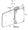
- FIG. 7 An example of a known door structure is disclosed in Japanese Laid-Open Utility Model JP-U-158322/81 (Japanese Utility Model Application No. Sho 55-58647), which is shown in Figure 7 of the present application.
- a rear end portion 102 of a door window 100 is fixed to a slider 200 which guides the door window 100 during the vertical displacement thereof.
- An adhesive 50 is provided between the rear end portion 102 of the door window 100 and the slider 200 to fix the slider 200 to the door window 100.
- Figure 7 shows that an upper surface 202 of the slider 200 is horizontally sectioned. The adhesive 50 is not enclosed by any portion of the slider 200, which permits the adhesive 50 to spread onto the upper surface 202 of the slider 200.
- the present invention was made in view of the foregoing background and to overcome the foregoing drawbacks. It is accordingly an object of this invention to provide an improved vehicle door structure, wherein the adhesive employed for fixing a door window to the slider does not spread onto undesirable surfaces of the slider.
- the invention provides a vehicle door structure, comprising a door frame mounted onto a vehicle such that it opens and closes for a passenger's ingress or egress, a door window having a plurality of corner portions, the door window being provided in the door frame such that an exterior surface of the door window is substantially flush with an exterior surface of the door frame, and a slider having a longitudinal groove therein to receive a side edge portion of the door window which is secured therein by an adhesive introduced into the groove, the slider acting to guide the door window along the door frame during an upward and downward displacement thereof, characterized in that the slider is formed at its upper end with a portion which closes the upper end of said groove therein and, together with opposite side walls of said groove, surrounds one of the plurality of corner portions of the door window, so that when the adhesive is introduced into said groove in the slider, the adhesive does not spread onto the upper end surface of the slider.
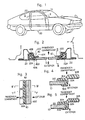
- FIG 1 shows a perspective view of a vehicle body which utilizes a structure according to the present invention.
- a door window 10 is mounted such that it can be upwardly and downwardly displaced, by any known means of operation, within a door frame 22 of a door 20.
- Figure 2 shows an enlarged cross-sectional view taken along the line II-II in Figure 1.
- the door window 10 is mounted within the door frame 22.
- the door frame 22 has door window guide grooves 220 and 222 at front and rear portions of the frame 22.
- a cushioning member 224 is provided within the grooves 220 and 222.
- the sliders 30 and 40 are fixed to the door window 10 at the front and rear end portions thereof.
- Figures 4 and 5 show that the slider 30, which, for example, is made of synthetic resin, comprises an exterior portion 302, an interior portion 304, and a connecting portion 306 which connects the exterior portion 302 with the interior portion 304.
- the slider 30 also has an elongated front end portion 308.
- the exterior portion 302 of the front slider 30 extends in an almost parallel relationship with the exterior surface of the door window 10, and is almost flush with the exterior surface of the door frame 22.
- the interior portion 304 of the front slider 30 similarly extends in a parallel relationship with the ' interior surface of the door window 10.
- the connecting portion 306 of the slider 30 extends laterally across the door frame and connects the interior portion 304 with the exterior portion 302.
- the interior portion 304 of the slider 30 forwardly extends in the vehicle to form the elongated front end portion 308.
- the forward end of the elongated front end portion 308 is fitted into the cushioning member 224.
- a rear slider 40 can also be made of synthetic resin and comprises an exterior portion 402, an interior portion 404, a connecting portion 406, and an elongated rear end portion 408.
- the exterior portion 402 of the rear slider 40 extends in an almost parallel relationship with the exterior surface of the door window 10, and is almost flush with the exterior surface of the door frame 22.
- the interior portion 404 of the rear slider 40 extends in an almost parallel relationship with the interior surface of the door window 10.
- the connecting portion 406 of the rear slider 40 extends laterally across the door frame and connects the interior portion 404 with the exterior portion 402.
- the interior portion 404 of the slider 40 extends rearwardly to form the elongated rear end portion 408.
- the rearward end of the elongated portion 408 fits into the groove 222 and is surrounded by the cushioning member 224.
- the portions 304 and 306 of the front slider 30 have ribs 310 which partially surround the front portion of the door window 10. As shown in Figure 3, a plurality of ribs 310 are separately provided at different vertical positions such that they properly locate the door window 10 within the slider 30.
- the front end of the door window 10 is fitted into the space defined between the portions 302, 304 and 306 of the slider 30.
- An adhesive 50 such as silicon adhesive or urethane adhesive, is fitted into the space between the door window 10 and the ribs 310, as shown in Figure 5.
- the adhesive 50 fixes the slider 30 to the front end of the door window 10.
- the slider 40 is similarly fixed to the rear end of the door window 10.
- Figure 6 shows a partial perspective view which illustrates a portion of the vehicle door structure according to the present invention.
- a rearward upper corner portion 12 of the door window 10 is inclined as shown in Figure 6.
- the inclined corner portion 12 of the door window 10 is slidably fitted into a groove in the slider 40.
- the upper end surface 42 of the slider 40 is designed such that it has a flat upper surface which encloses the inclined corner portion 12 of the door window 10 underneath.
- the adhesive 50 which connects the slider 30 to the door window does not spread out onto the upper surface 42 of the slider 40. Hence, the undesirable features of the prior art have been obviated.
- a forward upper corner portion of a door window can be similarly surrounded by a slider such that both the forward and rearward upper corner portions of the door window prevent the adhesive 50 from spreading onto the upper end surface of the slider.
Landscapes
- Engineering & Computer Science (AREA)
- Mechanical Engineering (AREA)
- Window Of Vehicle (AREA)
- Seal Device For Vehicle (AREA)
Description
- The present invention relates generally to a vehicle door structure, and more particularly to a vehicle door structure having an exterior surface portion of a door window located in a vehicle door, such that it is almost flush with an exterior surface portion of an enclosing door frame. Further, the present invention provides an apparatus which secures more reliably a door window to a resilient member, the resilient member being attached by an adhesive substance to the door window.
- This invention reduces undesirable air resistance and noise which are generated by wind passing across the exterior surface portions of the window and door frame. Further, this door structure eliminates the narrow field of vision which is present in known devices. The vehicle door structure also improves the door assembly in that it provides for more reliable attachment between a resilient member and the door window.
- An example of a known door structure is disclosed in Japanese Laid-Open Utility Model JP-U-158322/81 (Japanese Utility Model Application No. Sho 55-58647), which is shown in Figure 7 of the present application. According to this known structure, a
rear end portion 102 of adoor window 100 is fixed to aslider 200 which guides thedoor window 100 during the vertical displacement thereof. An adhesive 50 is provided between therear end portion 102 of thedoor window 100 and theslider 200 to fix theslider 200 to thedoor window 100. Figure 7 shows that anupper surface 202 of theslider 200 is horizontally sectioned. Theadhesive 50 is not enclosed by any portion of theslider 200, which permits theadhesive 50 to spread onto theupper surface 202 of theslider 200. When thedoor window 100 is displaced downwardly by any means of operation, a passenger sitting nearest to the door visually observes theupper surface 202 of theslider 200. Thus, if theadhesive 50 spreads out onto theupper surface 202 of theslider 200, dust, dirt and moisture can accumulate upon the adhesive. Further, the spreading of the adhesive is undesirable from an aesthetic standpoint as well. - The present invention was made in view of the foregoing background and to overcome the foregoing drawbacks. It is accordingly an object of this invention to provide an improved vehicle door structure, wherein the adhesive employed for fixing a door window to the slider does not spread onto undesirable surfaces of the slider.
- To attain the above objects, the invention provides a vehicle door structure, comprising a door frame mounted onto a vehicle such that it opens and closes for a passenger's ingress or egress, a door window having a plurality of corner portions, the door window being provided in the door frame such that an exterior surface of the door window is substantially flush with an exterior surface of the door frame, and a slider having a longitudinal groove therein to receive a side edge portion of the door window which is secured therein by an adhesive introduced into the groove, the slider acting to guide the door window along the door frame during an upward and downward displacement thereof, characterized in that the slider is formed at its upper end with a portion which closes the upper end of said groove therein and, together with opposite side walls of said groove, surrounds one of the plurality of corner portions of the door window, so that when the adhesive is introduced into said groove in the slider, the adhesive does not spread onto the upper end surface of the slider.
- The above objects, features and advantages of the present invention will become more apparent from the following description of the preferred embodiments taken in conjunction with the accompanying drawings, wherein:
- Fig. 1 is a perspective view of a vehicle body wherein a vehicle body structure according to the present invention is employed;
- Fig. 2 is an enlarged cross-sectional view taken along the line II-II in Figure 1;
- Fig. 3 is a partially enlarged cross-sectional view taken along the line III-III in Figure 2;
- Fig. 4 is a cross-sectional view taken along the line IV-IV in Figure 3;
- Fig. 5 is a cross-sectional view taken along the line V-V in Figure 3;
- Fig. 6 is a partial perspective view which illustrates the rear portion of the vehicle door structure according to the present invention; and
- Fig. 7 is a partial perspective view of a known vehicle door structure, illustrating its rear portion (as disclosed in JP-U-158322/81).
- The present invention is described in detail with reference to the accompanying drawings which illustrate different embodiments of the present invention.
- Figure 1 shows a perspective view of a vehicle body which utilizes a structure according to the present invention. A
door window 10 is mounted such that it can be upwardly and downwardly displaced, by any known means of operation, within adoor frame 22 of a door 20. Figure 2 shows an enlarged cross-sectional view taken along the line II-II in Figure 1. As shown in Figure 2, thedoor window 10 is mounted within thedoor frame 22. Thedoor frame 22 has doorwindow guide grooves frame 22. Acushioning member 224 is provided within thegrooves sliders door window 10 at the front and rear end portions thereof. Figures 4 and 5 show that theslider 30, which, for example, is made of synthetic resin, comprises anexterior portion 302, aninterior portion 304, and a connectingportion 306 which connects theexterior portion 302 with theinterior portion 304. Theslider 30 also has an elongatedfront end portion 308. Theexterior portion 302 of thefront slider 30 extends in an almost parallel relationship with the exterior surface of thedoor window 10, and is almost flush with the exterior surface of thedoor frame 22. Theinterior portion 304 of thefront slider 30 similarly extends in a parallel relationship with the' interior surface of thedoor window 10. The connectingportion 306 of theslider 30 extends laterally across the door frame and connects theinterior portion 304 with theexterior portion 302. Theinterior portion 304 of theslider 30 forwardly extends in the vehicle to form the elongatedfront end portion 308. The forward end of the elongatedfront end portion 308 is fitted into thecushioning member 224. - Similarly, a
rear slider 40 can also be made of synthetic resin and comprises anexterior portion 402, aninterior portion 404, a connectingportion 406, and an elongatedrear end portion 408. Theexterior portion 402 of therear slider 40 extends in an almost parallel relationship with the exterior surface of thedoor window 10, and is almost flush with the exterior surface of thedoor frame 22. Theinterior portion 404 of therear slider 40 extends in an almost parallel relationship with the interior surface of thedoor window 10. The connectingportion 406 of therear slider 40 extends laterally across the door frame and connects theinterior portion 404 with theexterior portion 402. Theinterior portion 404 of theslider 40 extends rearwardly to form the elongatedrear end portion 408. The rearward end of theelongated portion 408 fits into thegroove 222 and is surrounded by thecushioning member 224. - The
portions front slider 30 haveribs 310 which partially surround the front portion of thedoor window 10. As shown in Figure 3, a plurality ofribs 310 are separately provided at different vertical positions such that they properly locate thedoor window 10 within theslider 30. The front end of thedoor window 10 is fitted into the space defined between theportions slider 30. An adhesive 50, such as silicon adhesive or urethane adhesive, is fitted into the space between thedoor window 10 and theribs 310, as shown in Figure 5. Theadhesive 50 fixes theslider 30 to the front end of thedoor window 10. Theslider 40 is similarly fixed to the rear end of thedoor window 10. - Figure 6 shows a partial perspective view which illustrates a portion of the vehicle door structure according to the present invention. A rearward
upper corner portion 12 of thedoor window 10 is inclined as shown in Figure 6. Theinclined corner portion 12 of thedoor window 10 is slidably fitted into a groove in theslider 40. Theupper end surface 42 of theslider 40 is designed such that it has a flat upper surface which encloses theinclined corner portion 12 of thedoor window 10 underneath. Theadhesive 50 which connects theslider 30 to the door window does not spread out onto theupper surface 42 of theslider 40. Hence, the undesirable features of the prior art have been obviated. - Similarly, a forward upper corner portion of a door window can be similarly surrounded by a slider such that both the forward and rearward upper corner portions of the door window prevent the adhesive 50 from spreading onto the upper end surface of the slider.
Claims (10)
Applications Claiming Priority (6)
| Application Number | Priority Date | Filing Date | Title |
|---|---|---|---|
| JP1983195292U JPS60102125U (en) | 1983-12-19 | 1983-12-19 | car door structure |
| JP195292/83 | 1983-12-19 | ||
| JP20353883U JPS60105522U (en) | 1983-12-26 | 1983-12-26 | car door structure |
| JP203538/83 | 1983-12-26 | ||
| JP27643/84 | 1984-02-27 | ||
| JP2764384U JPS60138828U (en) | 1984-02-27 | 1984-02-27 | car door glass |
Publications (3)
| Publication Number | Publication Date |
|---|---|
| EP0146319A2 EP0146319A2 (en) | 1985-06-26 |
| EP0146319A3 EP0146319A3 (en) | 1986-10-01 |
| EP0146319B1 true EP0146319B1 (en) | 1988-04-27 |
Family
ID=27285886
Family Applications (2)
| Application Number | Title | Priority Date | Filing Date |
|---|---|---|---|
| EP84308511A Expired EP0146318B1 (en) | 1983-12-19 | 1984-12-06 | Vehicle door structure |
| EP84308512A Expired EP0146319B1 (en) | 1983-12-19 | 1984-12-06 | Vehicle door structure |
Family Applications Before (1)
| Application Number | Title | Priority Date | Filing Date |
|---|---|---|---|
| EP84308511A Expired EP0146318B1 (en) | 1983-12-19 | 1984-12-06 | Vehicle door structure |
Country Status (2)
| Country | Link |
|---|---|
| EP (2) | EP0146318B1 (en) |
| DE (2) | DE3476360D1 (en) |
Families Citing this family (2)
| Publication number | Priority date | Publication date | Assignee | Title |
|---|---|---|---|---|
| US4662113A (en) * | 1985-11-01 | 1987-05-05 | Libbey-Owens-Ford Co. | Window assembly and method of making the same |
| CN112252870B (en) * | 2020-10-09 | 2022-04-19 | 浙江吉利控股集团有限公司 | High energy storage stopper structure |
Family Cites Families (2)
| Publication number | Priority date | Publication date | Assignee | Title |
|---|---|---|---|---|
| DE2808235A1 (en) * | 1978-02-25 | 1979-08-30 | Audi Nsu Auto Union Ag | Flush mounting for sliding car window - has inwards directed edge tags which run in slides inside door frame |
| IT1128443B (en) * | 1980-05-15 | 1986-05-28 | Sirp Spa | STRUCTURE FOR SUPPORTING AND GUIDING VERTICALALLY MOVABLE CRYSTALS OF MOTOR VEHICLE SIDE WINDOWS |
-
1984
- 1984-12-06 DE DE8484308511T patent/DE3476360D1/en not_active Expired
- 1984-12-06 EP EP84308511A patent/EP0146318B1/en not_active Expired
- 1984-12-06 EP EP84308512A patent/EP0146319B1/en not_active Expired
- 1984-12-06 DE DE8484308512T patent/DE3470706D1/en not_active Expired
Also Published As
| Publication number | Publication date |
|---|---|
| EP0146318A3 (en) | 1986-09-17 |
| EP0146318B1 (en) | 1989-01-25 |
| EP0146318A2 (en) | 1985-06-26 |
| EP0146319A3 (en) | 1986-10-01 |
| DE3476360D1 (en) | 1989-03-02 |
| EP0146319A2 (en) | 1985-06-26 |
| DE3470706D1 (en) | 1988-06-01 |
Similar Documents
| Publication | Publication Date | Title |
|---|---|---|
| EP0195578B1 (en) | A vehicle door structure | |
| US4731951A (en) | Vehicle door structure | |
| US4691476A (en) | Vehicle door structure | |
| EP0040588A1 (en) | Structure for supporting and guiding vertically-movable panes in side windows of motorvehicle bodies | |
| EP0327141A2 (en) | Structure for windows in an automobile | |
| GB2167357A (en) | Vehicle roof assemblies | |
| EP0126895A1 (en) | Construction of roofside portion of motor vehicle | |
| JP2879089B2 (en) | Car waist belt structure | |
| EP0171865A1 (en) | A vehicle door structure | |
| GB2068306A (en) | Automobile door structure | |
| EP0584945A1 (en) | Vehicle seat assembly with extending seat track trim cover | |
| EP0040587A2 (en) | Structure for supporting and guiding vertically-movable panes in the side windows of motor-vehicle bodies | |
| US5253829A (en) | Vehicle sunroof deflector and mounting system | |
| EP0146319A2 (en) | Vehicle door structure | |
| EP0431964B1 (en) | Automobile window molding assembly | |
| EP0799748A1 (en) | An elongate strip | |
| EP0167362A2 (en) | A vehicle door structure | |
| US5609387A (en) | Lining panel for a sliding roof for a vehicle | |
| US4616445A (en) | Construction of door in motor vehicle | |
| EP0188212B1 (en) | Window glass guide system for vehicle | |
| US4625458A (en) | Vehicle door structure | |
| US4805958A (en) | Sunroof housing for automative vehicles | |
| US8024893B2 (en) | Powered slider drive interface and drive assembly | |
| JPS58218474A (en) | Construction of cowl top part in automobile | |
| JPH0645306B2 (en) | Structure of Molding Section of Grass Run |
Legal Events
| Date | Code | Title | Description |
|---|---|---|---|
| PUAI | Public reference made under article 153(3) epc to a published international application that has entered the european phase |
Free format text: ORIGINAL CODE: 0009012 |
|
| AK | Designated contracting states |
Designated state(s): DE FR GB |
|
| 17P | Request for examination filed |
Effective date: 19850819 |
|
| PUAL | Search report despatched |
Free format text: ORIGINAL CODE: 0009013 |
|
| AK | Designated contracting states |
Kind code of ref document: A3 Designated state(s): DE FR GB |
|
| 17Q | First examination report despatched |
Effective date: 19870513 |
|
| GRAA | (expected) grant |
Free format text: ORIGINAL CODE: 0009210 |
|
| AK | Designated contracting states |
Kind code of ref document: B1 Designated state(s): DE FR GB |
|
| REF | Corresponds to: |
Ref document number: 3470706 Country of ref document: DE Date of ref document: 19880601 |
|
| ET | Fr: translation filed | ||
| PLBE | No opposition filed within time limit |
Free format text: ORIGINAL CODE: 0009261 |
|
| STAA | Information on the status of an ep patent application or granted ep patent |
Free format text: STATUS: NO OPPOSITION FILED WITHIN TIME LIMIT |
|
| 26N | No opposition filed | ||
| PGFP | Annual fee paid to national office [announced via postgrant information from national office to epo] |
Ref country code: GB Payment date: 19911122 Year of fee payment: 8 |
|
| PGFP | Annual fee paid to national office [announced via postgrant information from national office to epo] |
Ref country code: FR Payment date: 19911209 Year of fee payment: 8 |
|
| PGFP | Annual fee paid to national office [announced via postgrant information from national office to epo] |
Ref country code: DE Payment date: 19920131 Year of fee payment: 8 |
|
| PG25 | Lapsed in a contracting state [announced via postgrant information from national office to epo] |
Ref country code: GB Effective date: 19921206 |
|
| GBPC | Gb: european patent ceased through non-payment of renewal fee |
Effective date: 19921206 |
|
| PG25 | Lapsed in a contracting state [announced via postgrant information from national office to epo] |
Ref country code: FR Effective date: 19930831 |
|
| PG25 | Lapsed in a contracting state [announced via postgrant information from national office to epo] |
Ref country code: DE Effective date: 19930901 |
|
| REG | Reference to a national code |
Ref country code: FR Ref legal event code: ST |