EP0145847B1 - Gas cooling and recirculating device in continuous strip furnaces - Google Patents
Gas cooling and recirculating device in continuous strip furnaces Download PDFInfo
- Publication number
- EP0145847B1 EP0145847B1 EP84110447A EP84110447A EP0145847B1 EP 0145847 B1 EP0145847 B1 EP 0145847B1 EP 84110447 A EP84110447 A EP 84110447A EP 84110447 A EP84110447 A EP 84110447A EP 0145847 B1 EP0145847 B1 EP 0145847B1
- Authority
- EP
- European Patent Office
- Prior art keywords
- cooling
- box
- furnace
- vertically arranged
- recirculating
- Prior art date
- Legal status (The legal status is an assumption and is not a legal conclusion. Google has not performed a legal analysis and makes no representation as to the accuracy of the status listed.)
- Expired
Links
- 238000001816 cooling Methods 0.000 title claims abstract description 55
- 230000003134 recirculating effect Effects 0.000 title claims abstract description 39
- 230000001681 protective effect Effects 0.000 claims abstract description 22
- 238000000137 annealing Methods 0.000 claims abstract description 5
- 239000002184 metal Substances 0.000 claims description 4
- 229910000831 Steel Inorganic materials 0.000 abstract description 4
- 239000010959 steel Substances 0.000 abstract description 4
- 230000015556 catabolic process Effects 0.000 description 3
- 238000010276 construction Methods 0.000 description 3
- 238000012423 maintenance Methods 0.000 description 2
- 238000005192 partition Methods 0.000 description 2
- 239000012080 ambient air Substances 0.000 description 1
- 239000000498 cooling water Substances 0.000 description 1
- XLYOFNOQVPJJNP-UHFFFAOYSA-N water Substances O XLYOFNOQVPJJNP-UHFFFAOYSA-N 0.000 description 1
- 238000003466 welding Methods 0.000 description 1
Images


Classifications
-
- C—CHEMISTRY; METALLURGY
- C21—METALLURGY OF IRON
- C21D—MODIFYING THE PHYSICAL STRUCTURE OF FERROUS METALS; GENERAL DEVICES FOR HEAT TREATMENT OF FERROUS OR NON-FERROUS METALS OR ALLOYS; MAKING METAL MALLEABLE, e.g. BY DECARBURISATION OR TEMPERING
- C21D9/00—Heat treatment, e.g. annealing, hardening, quenching or tempering, adapted for particular articles; Furnaces therefor
- C21D9/52—Heat treatment, e.g. annealing, hardening, quenching or tempering, adapted for particular articles; Furnaces therefor for wires; for strips ; for rods of unlimited length
- C21D9/54—Furnaces for treating strips or wire
- C21D9/56—Continuous furnaces for strip or wire
- C21D9/573—Continuous furnaces for strip or wire with cooling
Definitions
- the invention relates to a device for the cooling and recirculation of the gas forming the protective atmosphere in the cooling chambers of furnaces for the continuous processing of metal strips, particularly for the continuous annealing of metal strips, which comprises vertically arranged boxes extending between the successive vertically extending parallel sections of the strip, substantially over the whole height thereof and whose walls turned toward the adjacent strip sections are provided with perforations, with each of said boxes there being associated a plurality of protective gas-cooling and recirculating units comprising each a heat exchanger and a fan, which fan draws from the furnace interior the protective gas and cools the same by causing it to flow through the heat exchanger, and blows at a certain pressure the protective gas into the associated box, the protective gas flowing out of the perforations provided in the box in form of jets being directed to the facing surfaces of the adjacent strip sections to cause the cooling thereof, the said individual cooling and recirculating units associated with each box being attached to the outside of both opposite furnace sidewalls.
- a device of this kind so-called “jet cooler” is disclosed in US-A-3068586, in which the cooling and recirculating units associated with each perforated box and located at opposite sidewalls of the furnace, are arranged at the same level, the one opposite to the other, and the cooling and recirculating units that are located on the same sidewall of the furnace are arranged the one beside the other at a same level forming continuous horizontal rows.
- GB-A-975 408 discloses a device in which cooling and recirculating units located at opposite furnace sidewalls are disposed in vertically staggered positions, but the cooling and recirculating units provided on the same sidewall of the furnace in adjacent vertical rows are mutually aligned and form horizontal rows. Furthermore, in the device according to GB-A-975 408 the perforated boxes do not extend over the whole height of the vertical parallel sections of the strip, a plurality of boxes of this type being instead provided one over the other, and this boxes extend each over a fraction of the height of the vertical parallel strip sections.
- each single cooling and recirculating unit is associated with two, i.e., more than one, perforated boxes.
- a drawback of the known devices with horizontally arranged individual boxes resides in the fact that when one or more of the individual protective gas-cooling and recirculating units, respectively associated to the horizontally arranged individual boxes forming part of the same vertically extending file of these boxes, should stop owing to a failure, a local unbalance in the pressures acting on the strip might be produced whenever all the cooling and recirculating units in the next-adjacent vertically extending file of individual horizontally arranged boxes continue to be regularly operated, so that they tend to push the strip toward the individual horizontally arranged boxes comprising the cooling and recirculating units affected by a failure, and the strip is then caused to rub against the structure of these individual boxes.
- the surface of the strip may be damaged, and the final quality of the strip may be inevitably deteriorated.
- the cooling and recirculating units of the facing horizontally extending boxes in the opposite file might be intentionally excluded, but this would determine a further important reduction in the overall cooling capacity.
- the object of the invention is to eliminate the drawbacks of the known devices, and for this purpose the invention provides a cooling and recirculating device of the kind as disclosed at the beginning, characterized in that the individual cooling and recirculating units associated with each perforated box are distributed over the entire vertical extent of the respective box and forming rows at opposite furnace sidewalls, these rows being disposed in vertically staggered positions and the vertically extending row of the cooling and recirculating units associated with each vertically arranged perforated box on each sidewall of the furnace is vertically offset from the vertical row of the cooling and recirculating units associated with the adjacent vertically arranged box or boxes on the same sidewall of the furnace.
- the cooling and recirculating device of the invention affords the advantage of avoiding any local pressure unbalance in the case of a breakdown and a stopping of one or more of the individual cooling and recirculating units associated to the same vertically arranged perforated box.
- the pressure decrease within the perforated vertically arranged box connected to the broken down cooling and recirculating unit or units is not limited to a localized relatively short section, but will spread through the respective vertically arranged perforated box, i.e. throughout the height of the furnace, so that a relatively small decrease of the total pressure in the said vertically arranged box will be produced.
- the device of the invention affords all the advantages typical of the perforated vertically arranged boxes, particularly a higher cooling efficiency, since for the cooling protective gas jets directed against the strip it is taken advantage of all the furnace height, and not of only one portion thereof.
- the device of the invention furthermore affords the advantages of a simpler construction and a lower cost with reference to the attained performances, as well as the advantages of being very strong and of requiring practically no maintenance, or anyhow very little maintenance.
- the device of the invention is of a reduced weight, whereby it can be more easily disassembled and reassembled.
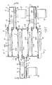
- numeral 1 denotes the two opposite sidewalls of the final cooling chamber of a furnace for the continuous annealing of steel strips.
- the steel strip N is alternately led around upper and lower guide rollers 2, 3, so that it presents spaced apart, vertically extending parallel sections therebetween.
- vertically arranged boxes 4 are provided between the vertically extending sections of the strip N; these boxes are rectangularly shaped in horizontal cross-section, and extend substantially over the whole length of the said vertically extending strip sections, i.e., practically throughout the height of the furnace.
- the two opposite longitudinal sidewalls 104 of boxes 4, which are turned toward the strip N, are provided with perforations 5.
- a plurality of units 6 for the cooling and recirculation of the gas (such as, for example, HNX) forming the protective atmosphere in the furnace, are provided on the furnace outside, along each vertically arranged box 4.
- the superposed successive cooling and recirculating units 6 which are associated to each vertically arranged box 4 are alternatingly provided on both of the furnace opposite sidewalls, and the vertically extending file of the spaced apart cooling and recirculating units 6, which are associated to one vertically arranged box 4, is vertically offset from the vertically extending row of the cooling and recirculating units 6 which are associated to the adjacent vertically arranged box or boxes 4.
- the access will be facilitated to every one of the cooling and recirculating units 6, as well as their fitting up and their removal.
- Each protective gas-cooling and recirculating unit 6 consists of a sealed case element 7 which is tightly attached, such as by welding, onto the outside of the respective furnace sidewall 1, and which by means of an internal vertical partition 8 substantially perpendicular to the furnace sidewall 1, is compared into a suction chamber 9 and into a delivery chamber 10 lying therebeside.
- the delivery chamber 10 communicates with the interior of the box 4 that is associated with the appertaining cooling and recirculating unit 6.
- the suction chamber 9 communicates with the interior of the furnace, through a suction port 109 in the corresponding furnace sidewall 1. Both the suction port 109 and the delivery port 110 are situated on the inner side of the edge by which the case 7 is tightly attached to the furnace sidewall 1.
- the suction chamber 9 and the delivery chamber 10 are in communication with each other through a port provided in the partition 8, and forming the suction inlet of a preferably centrifugal fan accomodated in the delivery chamber 10.
- the delivery outlet of said fan 11 opens into the delivery chamber 10 itself.
- the fan 11 is driven by an electric motor which is flange- mounted directly onto the case element 7 of the respective cooling and recirculating unit 6.
- a heat exchanger consisting of a group of rectilinear finned tubes 13 tightly passed through the suction chamber 9 of the case element 7 in the vertical direction, and in which cooling water flows.
- each cooling and recirculating unit 6 draws the protective gas from the furnace interior through the suction chamber 9 and the suction inlet 108, thus causing the said gas to flow between the water cooling tubes 13 of the heat exchanger provided in the said suction chamber, and so suitably cooling this gas.
- the fan 11 blows with a certain pressure the thus cooled protective gas through the delivery chamber and the delivery port 110 into the associated vertically arranged box 4.
- This gas flows out of this vertically arranged box 4 through the perforations 5 in its opposite sidewalls 104, in form of jets directed to the facing surfaces of the two vertically extending sections of strip N, to cool the said strip.
- the cooling and recirculating units 6 are of perfectly tight construction, whereby it is reliably excluded any inflow of ambient air which would inevitably pollute the protective atmosphere in the furnace interior, and would result in the surface of the strip N being oxidated, and in the subsequent tinning thereof being impossible.
Landscapes
- Chemical & Material Sciences (AREA)
- Engineering & Computer Science (AREA)
- Materials Engineering (AREA)
- Thermal Sciences (AREA)
- Crystallography & Structural Chemistry (AREA)
- Mechanical Engineering (AREA)
- Physics & Mathematics (AREA)
- Metallurgy (AREA)
- Organic Chemistry (AREA)
- Heat Treatment Of Strip Materials And Filament Materials (AREA)
- Processing Of Meat And Fish (AREA)
- Electrical Discharge Machining, Electrochemical Machining, And Combined Machining (AREA)
- Surgical Instruments (AREA)
- Heat Treatments In General, Especially Conveying And Cooling (AREA)
Abstract
Description
- The invention relates to a device for the cooling and recirculation of the gas forming the protective atmosphere in the cooling chambers of furnaces for the continuous processing of metal strips, particularly for the continuous annealing of metal strips, which comprises vertically arranged boxes extending between the successive vertically extending parallel sections of the strip, substantially over the whole height thereof and whose walls turned toward the adjacent strip sections are provided with perforations, with each of said boxes there being associated a plurality of protective gas-cooling and recirculating units comprising each a heat exchanger and a fan, which fan draws from the furnace interior the protective gas and cools the same by causing it to flow through the heat exchanger, and blows at a certain pressure the protective gas into the associated box, the protective gas flowing out of the perforations provided in the box in form of jets being directed to the facing surfaces of the adjacent strip sections to cause the cooling thereof, the said individual cooling and recirculating units associated with each box being attached to the outside of both opposite furnace sidewalls.
- A device of this kind, so-called "jet cooler", is disclosed in US-A-3068586, in which the cooling and recirculating units associated with each perforated box and located at opposite sidewalls of the furnace, are arranged at the same level, the one opposite to the other, and the cooling and recirculating units that are located on the same sidewall of the furnace are arranged the one beside the other at a same level forming continuous horizontal rows.
- GB-A-975 408 discloses a device in which cooling and recirculating units located at opposite furnace sidewalls are disposed in vertically staggered positions, but the cooling and recirculating units provided on the same sidewall of the furnace in adjacent vertical rows are mutually aligned and form horizontal rows. Furthermore, in the device according to GB-A-975 408 the perforated boxes do not extend over the whole height of the vertical parallel sections of the strip, a plurality of boxes of this type being instead provided one over the other, and this boxes extend each over a fraction of the height of the vertical parallel strip sections. Finally, in the device according to GB-A-975 408 with each one of the perforated, vertically arranged boxes there is not associated a plurality of cooling and recirculating units, but each single cooling and recirculating unit is associated with two, i.e., more than one, perforated boxes.
- A drawback of the known devices with horizontally arranged individual boxes resides in the fact that when one or more of the individual protective gas-cooling and recirculating units, respectively associated to the horizontally arranged individual boxes forming part of the same vertically extending file of these boxes, should stop owing to a failure, a local unbalance in the pressures acting on the strip might be produced whenever all the cooling and recirculating units in the next-adjacent vertically extending file of individual horizontally arranged boxes continue to be regularly operated, so that they tend to push the strip toward the individual horizontally arranged boxes comprising the cooling and recirculating units affected by a failure, and the strip is then caused to rub against the structure of these individual boxes. By such a rubbing, the surface of the strip may be damaged, and the final quality of the strip may be inevitably deteriorated. In order to reset a pressure balance and avoid the said rubbing of the strip, in the instance of a breakdown and a stopping of a certain number of cooling and recirculating units, respectively associated to the individual vertically arranged boxes in the same vertically extending file, the cooling and recirculating units of the facing horizontally extending boxes in the opposite file might be intentionally excluded, but this would determine a further important reduction in the overall cooling capacity.
- The object of the invention is to eliminate the drawbacks of the known devices, and for this purpose the invention provides a cooling and recirculating device of the kind as disclosed at the beginning, characterized in that the individual cooling and recirculating units associated with each perforated box are distributed over the entire vertical extent of the respective box and forming rows at opposite furnace sidewalls, these rows being disposed in vertically staggered positions and the vertically extending row of the cooling and recirculating units associated with each vertically arranged perforated box on each sidewall of the furnace is vertically offset from the vertical row of the cooling and recirculating units associated with the adjacent vertically arranged box or boxes on the same sidewall of the furnace.
- With regard to the known constructions comprising perforated individual boxes horizontally arranged in a superposed aligned relation, the cooling and recirculating device of the invention affords the advantage of avoiding any local pressure unbalance in the case of a breakdown and a stopping of one or more of the individual cooling and recirculating units associated to the same vertically arranged perforated box. In fact, in such a case, the pressure decrease within the perforated vertically arranged box connected to the broken down cooling and recirculating unit or units is not limited to a localized relatively short section, but will spread through the respective vertically arranged perforated box, i.e. throughout the height of the furnace, so that a relatively small decrease of the total pressure in the said vertically arranged box will be produced. This decrease of the total pressure within the vertically arranged perforated box connected to the cooling and recirculating unit or units affected by a breakdown, is unlikely to become so great as to cause the strip to be rubbed against the structure of said box under the action of the protective gas jets being directed against the opposite face of the strip, and flowing out of the opposite respective vertically arranged perforated box having all its associated cooling and recirculating units working properly.
- Besides this automatic balancing of the pressure in the interior of the perforated boxes, the device of the invention affords all the advantages typical of the perforated vertically arranged boxes, particularly a higher cooling efficiency, since for the cooling protective gas jets directed against the strip it is taken advantage of all the furnace height, and not of only one portion thereof.
- The device of the invention furthermore affords the advantages of a simpler construction and a lower cost with reference to the attained performances, as well as the advantages of being very strong and of requiring practically no maintenance, or anyhow very little maintenance. The device of the invention is of a reduced weight, whereby it can be more easily disassembled and reassembled.
- The characteristic features of the invention and the advantages arising therefrom will clearly appear also in the following specification of one preferred embodiment thereof, diagrammatically shown by way of a non-limiting example in the accompanying drawings, in which:
- Figure 1 is a partial vertical section through the final cooling chamber of a furnace for the continuous annealing of steel strips, and the said vertical section is taken along a plane being directed transversely to the horizontal rectangular cross-section of the perforated vertically arranged boxes provided in the furnace interior, that is to say, substantially on line I-I in Figure 2.
- Figure 2 is a partial horizontal cross-section, for example taken on line 11-11 in Figures 1 and 3.
- Figure 3 is a partial vertical section taken along a plane being directed longitudinally of the rectangular horizontal cross-section of the perforated vertically arranged boxes, substantially on line III-III in Figure 2.
- Referring to the Figures,
numeral 1 denotes the two opposite sidewalls of the final cooling chamber of a furnace for the continuous annealing of steel strips. The steel strip N is alternately led around upper andlower guide rollers 2, 3, so that it presents spaced apart, vertically extending parallel sections therebetween. In the interior of the furnace vertically arrangedboxes 4 are provided between the vertically extending sections of the strip N; these boxes are rectangularly shaped in horizontal cross-section, and extend substantially over the whole length of the said vertically extending strip sections, i.e., practically throughout the height of the furnace. The two oppositelongitudinal sidewalls 104 ofboxes 4, which are turned toward the strip N, are provided withperforations 5. - A plurality of
units 6 for the cooling and recirculation of the gas (such as, for example, HNX) forming the protective atmosphere in the furnace, are provided on the furnace outside, along each vertically arrangedbox 4. Preferably, the superposed successive cooling and recirculatingunits 6 which are associated to each vertically arrangedbox 4, are alternatingly provided on both of the furnace opposite sidewalls, and the vertically extending file of the spaced apart cooling and recirculatingunits 6, which are associated to one vertically arrangedbox 4, is vertically offset from the vertically extending row of the cooling and recirculatingunits 6 which are associated to the adjacent vertically arranged box orboxes 4. Thus the access will be facilitated to every one of the cooling and recirculatingunits 6, as well as their fitting up and their removal. - Each protective gas-cooling and recirculating
unit 6 consists of a sealedcase element 7 which is tightly attached, such as by welding, onto the outside of therespective furnace sidewall 1, and which by means of an internalvertical partition 8 substantially perpendicular to thefurnace sidewall 1, is compared into asuction chamber 9 and into adelivery chamber 10 lying therebeside. Through adelivery port 110 in thecorresponding sidewall 1 of the furnace, thedelivery chamber 10 communicates with the interior of thebox 4 that is associated with the appertaining cooling and recirculatingunit 6. Through one side of the associated vertically arrangedbox 4 thesuction chamber 9 communicates with the interior of the furnace, through asuction port 109 in thecorresponding furnace sidewall 1. Both thesuction port 109 and thedelivery port 110 are situated on the inner side of the edge by which thecase 7 is tightly attached to thefurnace sidewall 1. - The
suction chamber 9 and thedelivery chamber 10 are in communication with each other through a port provided in thepartition 8, and forming the suction inlet of a preferably centrifugal fan accomodated in thedelivery chamber 10. The delivery outlet of saidfan 11 opens into thedelivery chamber 10 itself. Thefan 11 is driven by an electric motor which is flange- mounted directly onto thecase element 7 of the respective cooling and recirculatingunit 6. In thesuction chamber 9, between theport 109 communicating with the interior of the perforated vertically arrangedbox 4, and the suction inlet offan 11, there is provided a heat exchanger consisting of a group of rectilinearfinned tubes 13 tightly passed through thesuction chamber 9 of thecase element 7 in the vertical direction, and in which cooling water flows. - From the foregoing it appears evident that the
fan 11 of each cooling and recirculatingunit 6 draws the protective gas from the furnace interior through thesuction chamber 9 and thesuction inlet 108, thus causing the said gas to flow between thewater cooling tubes 13 of the heat exchanger provided in the said suction chamber, and so suitably cooling this gas. Thefan 11 blows with a certain pressure the thus cooled protective gas through the delivery chamber and thedelivery port 110 into the associated vertically arrangedbox 4. This gas flows out of this vertically arrangedbox 4 through theperforations 5 in itsopposite sidewalls 104, in form of jets directed to the facing surfaces of the two vertically extending sections of strip N, to cool the said strip. - The cooling and recirculating
units 6 are of perfectly tight construction, whereby it is reliably excluded any inflow of ambient air which would inevitably pollute the protective atmosphere in the furnace interior, and would result in the surface of the strip N being oxidated, and in the subsequent tinning thereof being impossible.
Claims (1)
- A device for the cooling and recirculation of the gas forming the protective atmosphere in the cooling chambers of furnaces for the continuous processing of metal strips, particularly for the continuous annealing of metal strips, which comprises vertically arranged boxes (4) extending between the successive vertically extending parallel sections of the strip, substantially over the whole height thereof and whose walls (104) turned toward the adjacent strip sections are provided with perforations (5), with each of said boxes there being associated a plurality of protective gas-cooling and recirculating units (6) comprising each a heat exchanger (13) and a fan (11), which fan draws from the furnace interior the protective gas and cools the same by causing it to flow through the heat exchanger (13), and blows at a certain pressure the protective gas into the associated box (4), the protective gas flowing out of the perforations (5) provided in the box (4) in form of jets being directed to the facing surfaces of the adjacent strip sections to cause the cooling thereof, the said individual cooling and recirculating units (6) associated with each box (4) being attached to the outside of both opposite furnace sidewalls (1), characterized in that the units (6) of each box (4) are distributed over the entire vertical extent of the respective box (4) and forming rows at opposite furnace sidewalls, these rows being disposed in vertically staggered positions, and the vertically extending row of the cooling and recirculating units (6) associated with each vertically arranged perforated box (4) on each sidewall (1) of the furnace is vertically offset from the vertical row of the cooling and recirculating units (6) associated with the adjacent vertically arranged box or boxes (4) on the same sidewall (1) of the furnace.
Priority Applications (1)
| Application Number | Priority Date | Filing Date | Title |
|---|---|---|---|
| AT84110447T ATE31554T1 (en) | 1983-09-08 | 1984-09-03 | DEVICE FOR CIRCULATION AND COOLING OF GAS IN CONTINUOUS CONVEYOR FURNACES. |
Applications Claiming Priority (2)
| Application Number | Priority Date | Filing Date | Title |
|---|---|---|---|
| IT12617/83A IT1174829B (en) | 1983-09-08 | 1983-09-08 | DEVICE FOR COOLING AND RECIRCULATING THE GAS OF THE EXISTING PROTECTIVE ATMOSPHERE IN THE COOLING CHAMBER OF OVENS CONTINUOUS COOKING OF STEEL TAPES |
| IT1261783 | 1983-09-08 |
Publications (2)
| Publication Number | Publication Date |
|---|---|
| EP0145847A1 EP0145847A1 (en) | 1985-06-26 |
| EP0145847B1 true EP0145847B1 (en) | 1987-12-23 |
Family
ID=11142237
Family Applications (1)
| Application Number | Title | Priority Date | Filing Date |
|---|---|---|---|
| EP84110447A Expired EP0145847B1 (en) | 1983-09-08 | 1984-09-03 | Gas cooling and recirculating device in continuous strip furnaces |
Country Status (7)
| Country | Link |
|---|---|
| US (1) | US4600181A (en) |
| EP (1) | EP0145847B1 (en) |
| AT (1) | ATE31554T1 (en) |
| BR (1) | BR8404444A (en) |
| CA (1) | CA1223124A (en) |
| DE (1) | DE3468237D1 (en) |
| IT (1) | IT1174829B (en) |
Families Citing this family (7)
| Publication number | Priority date | Publication date | Assignee | Title |
|---|---|---|---|---|
| JPS61157641A (en) * | 1984-12-28 | 1986-07-17 | Chugai Ro Kogyo Kaisha Ltd | Continuous annealing furnace for metallic strip |
| DE3616955A1 (en) * | 1986-05-20 | 1987-11-26 | Dornier Gmbh Lindauer | FILM STRETCHER WITH SEVERAL, FOLLOWING TREATMENT FIELDS |
| US5291670A (en) * | 1988-12-23 | 1994-03-08 | S.I.C.M.E. S.P.A. Societa Industriale Costruzioni Microelettriche | Process for baking wire-like products clad in insulating plastics resin, and an oven for performing the said method |
| FR2738577B1 (en) * | 1995-09-12 | 1998-03-13 | Selas Sa | COOLING DEVICE FOR A LAMINATED PRODUCT |
| FR2769696B1 (en) * | 1997-10-15 | 1999-12-31 | Stein Heurtey | SAFETY SYSTEM FOR FAST COOLING OVENS OF METAL STRIPS |
| US8965185B2 (en) * | 2009-03-02 | 2015-02-24 | Btu International, Inc. | Infrared furnace system |
| CN113720161A (en) * | 2020-05-25 | 2021-11-30 | 湖南红太阳光电科技有限公司 | Rapid cooling system in furnace |
Family Cites Families (5)
| Publication number | Priority date | Publication date | Assignee | Title |
|---|---|---|---|---|
| US3068586A (en) * | 1959-02-18 | 1962-12-18 | Electric Furnace Co | Forced cooling means and method for continuous strip furnaces |
| US3102009A (en) * | 1960-03-28 | 1963-08-27 | Gen Electric | Apparatus for thermal treatment of metal |
| US3116788A (en) * | 1961-07-13 | 1964-01-07 | Midland Ross Corp | Convective cooling of continuously moving metal strip |
| JPS5942733B2 (en) * | 1979-10-31 | 1984-10-17 | 川崎製鉄株式会社 | Steel strip continuous annealing equipment |
| US4398700A (en) * | 1982-09-29 | 1983-08-16 | Midland-Ross Corporation | Annealing furnace with an improved cooling section |
-
1983
- 1983-09-08 IT IT12617/83A patent/IT1174829B/en active
-
1984
- 1984-08-29 CA CA000462048A patent/CA1223124A/en not_active Expired
- 1984-09-03 AT AT84110447T patent/ATE31554T1/en not_active IP Right Cessation
- 1984-09-03 DE DE8484110447T patent/DE3468237D1/en not_active Expired
- 1984-09-03 EP EP84110447A patent/EP0145847B1/en not_active Expired
- 1984-09-04 US US06/647,161 patent/US4600181A/en not_active Expired - Fee Related
- 1984-09-05 BR BR8404444A patent/BR8404444A/en not_active IP Right Cessation
Also Published As
| Publication number | Publication date |
|---|---|
| DE3468237D1 (en) | 1988-02-04 |
| EP0145847A1 (en) | 1985-06-26 |
| IT1174829B (en) | 1987-07-01 |
| US4600181A (en) | 1986-07-15 |
| CA1223124A (en) | 1987-06-23 |
| IT8312617A0 (en) | 1983-09-08 |
| BR8404444A (en) | 1985-07-30 |
| ATE31554T1 (en) | 1988-01-15 |
Similar Documents
| Publication | Publication Date | Title |
|---|---|---|
| KR101619963B1 (en) | Warm floor data center | |
| JP2657054B2 (en) | Heat exchange method and heat exchange device | |
| US5018572A (en) | Steam condenser | |
| US8254121B2 (en) | Cooler and display device having the same | |
| US3068586A (en) | Forced cooling means and method for continuous strip furnaces | |
| US4873028A (en) | Low silhouette cooling tower with trapezoidal fill and method of air flow therethrough | |
| US4600181A (en) | Gas cooling and recirculating device in continuous strip furnaces | |
| US3447598A (en) | Air cooled heat exchanger | |
| US4260013A (en) | Plate type heat exchanger | |
| US12474120B2 (en) | Induced draft heat rejection equipment with top mounted backward-curved centrifugal fans | |
| US5447422A (en) | Air-cooled oil-free rotary-type compressor | |
| US2573491A (en) | Air-cooling apparatus | |
| US3116788A (en) | Convective cooling of continuously moving metal strip | |
| JPS5840114B2 (en) | cooling tower | |
| KR100326722B1 (en) | Crossflow colling tower filler with reduced vapor cloud and cooling method | |
| SU661219A1 (en) | Air-cooled heat exchanger | |
| EP1766303B1 (en) | Freezing system | |
| US3677029A (en) | Evaporative condenser | |
| JPH0743084A (en) | Cross flow type cooling tower | |
| SE417641B (en) | Plate heat exchanger | |
| JPH0311249A (en) | Outdoor unit of outdoor set type refrigerator | |
| SU552492A1 (en) | Counterflow fan for cooling tower torn | |
| JPH0979768A (en) | Air-cooled heat exchanger | |
| KR20070039414A (en) | Cooling device for motor for steelmaking equipment | |
| US3259993A (en) | Apparatus and method for treating strip |
Legal Events
| Date | Code | Title | Description |
|---|---|---|---|
| PUAI | Public reference made under article 153(3) epc to a published international application that has entered the european phase |
Free format text: ORIGINAL CODE: 0009012 |
|
| AK | Designated contracting states |
Designated state(s): AT BE CH DE FR GB LI LU NL SE |
|
| 17P | Request for examination filed |
Effective date: 19850814 |
|
| 17Q | First examination report despatched |
Effective date: 19860403 |
|
| GRAA | (expected) grant |
Free format text: ORIGINAL CODE: 0009210 |
|
| AK | Designated contracting states |
Kind code of ref document: B1 Designated state(s): AT BE CH DE FR GB LI LU NL SE |
|
| PG25 | Lapsed in a contracting state [announced via postgrant information from national office to epo] |
Ref country code: AT Effective date: 19871223 |
|
| REF | Corresponds to: |
Ref document number: 31554 Country of ref document: AT Date of ref document: 19880115 Kind code of ref document: T |
|
| REF | Corresponds to: |
Ref document number: 3468237 Country of ref document: DE Date of ref document: 19880204 |
|
| ET | Fr: translation filed | ||
| PG25 | Lapsed in a contracting state [announced via postgrant information from national office to epo] |
Ref country code: GB Effective date: 19880903 |
|
| PLBE | No opposition filed within time limit |
Free format text: ORIGINAL CODE: 0009261 |
|
| STAA | Information on the status of an ep patent application or granted ep patent |
Free format text: STATUS: NO OPPOSITION FILED WITHIN TIME LIMIT |
|
| 26N | No opposition filed | ||
| GBPC | Gb: european patent ceased through non-payment of renewal fee | ||
| EPTA | Lu: last paid annual fee | ||
| EAL | Se: european patent in force in sweden |
Ref document number: 84110447.4 |
|
| PGFP | Annual fee paid to national office [announced via postgrant information from national office to epo] |
Ref country code: LU Payment date: 19960801 Year of fee payment: 13 |
|
| PGFP | Annual fee paid to national office [announced via postgrant information from national office to epo] |
Ref country code: FR Payment date: 19960809 Year of fee payment: 13 |
|
| PGFP | Annual fee paid to national office [announced via postgrant information from national office to epo] |
Ref country code: CH Payment date: 19960819 Year of fee payment: 13 |
|
| PG25 | Lapsed in a contracting state [announced via postgrant information from national office to epo] |
Ref country code: LU Free format text: LAPSE BECAUSE OF NON-PAYMENT OF DUE FEES Effective date: 19970903 |
|
| PG25 | Lapsed in a contracting state [announced via postgrant information from national office to epo] |
Ref country code: LI Free format text: LAPSE BECAUSE OF NON-PAYMENT OF DUE FEES Effective date: 19970930 Ref country code: FR Free format text: THE PATENT HAS BEEN ANNULLED BY A DECISION OF A NATIONAL AUTHORITY Effective date: 19970930 Ref country code: CH Free format text: LAPSE BECAUSE OF NON-PAYMENT OF DUE FEES Effective date: 19970930 |
|
| REG | Reference to a national code |
Ref country code: CH Ref legal event code: PL |
|
| REG | Reference to a national code |
Ref country code: FR Ref legal event code: ST |
|
| PGFP | Annual fee paid to national office [announced via postgrant information from national office to epo] |
Ref country code: DE Payment date: 19990906 Year of fee payment: 16 |
|
| PGFP | Annual fee paid to national office [announced via postgrant information from national office to epo] |
Ref country code: SE Payment date: 19990907 Year of fee payment: 16 |
|
| PGFP | Annual fee paid to national office [announced via postgrant information from national office to epo] |
Ref country code: NL Payment date: 19990930 Year of fee payment: 16 |
|
| PG25 | Lapsed in a contracting state [announced via postgrant information from national office to epo] |
Ref country code: SE Free format text: THE PATENT HAS BEEN ANNULLED BY A DECISION OF A NATIONAL AUTHORITY Effective date: 20000929 |
|
| PG25 | Lapsed in a contracting state [announced via postgrant information from national office to epo] |
Ref country code: NL Free format text: LAPSE BECAUSE OF NON-PAYMENT OF DUE FEES Effective date: 20010401 |
|
| EUG | Se: european patent has lapsed |
Ref document number: 84110447.4 |
|
| NLV4 | Nl: lapsed or anulled due to non-payment of the annual fee |
Effective date: 20010401 |
|
| PG25 | Lapsed in a contracting state [announced via postgrant information from national office to epo] |
Ref country code: DE Free format text: LAPSE BECAUSE OF NON-PAYMENT OF DUE FEES Effective date: 20010601 |
|
| PGFP | Annual fee paid to national office [announced via postgrant information from national office to epo] |
Ref country code: BE Payment date: 20031203 Year of fee payment: 20 |
|
| BE20 | Be: patent expired |
Owner name: *ITALIMPIANTI SOCIETA ITALIANA IMPIANTI P.A. Effective date: 20040903 |