EP0145841B1 - Torque control apparatus for enclosed compressors - Google Patents
Torque control apparatus for enclosed compressors Download PDFInfo
- Publication number
- EP0145841B1 EP0145841B1 EP84109884A EP84109884A EP0145841B1 EP 0145841 B1 EP0145841 B1 EP 0145841B1 EP 84109884 A EP84109884 A EP 84109884A EP 84109884 A EP84109884 A EP 84109884A EP 0145841 B1 EP0145841 B1 EP 0145841B1
- Authority
- EP
- European Patent Office
- Prior art keywords
- compressor
- torque
- detecting means
- control apparatus
- rotating portion
- Prior art date
- Legal status (The legal status is an assumption and is not a legal conclusion. Google has not performed a legal analysis and makes no representation as to the accuracy of the status listed.)
- Expired
Links
- 238000005057 refrigeration Methods 0.000 claims description 4
- 230000007613 environmental effect Effects 0.000 claims 1
- 230000006835 compression Effects 0.000 description 3
- 238000007906 compression Methods 0.000 description 3
- 230000001133 acceleration Effects 0.000 description 2
- 238000006243 chemical reaction Methods 0.000 description 2
- 238000010586 diagram Methods 0.000 description 2
- 230000010363 phase shift Effects 0.000 description 2
- 238000010276 construction Methods 0.000 description 1
- 238000013016 damping Methods 0.000 description 1
- 230000007423 decrease Effects 0.000 description 1
- 238000000638 solvent extraction Methods 0.000 description 1
Images

Classifications
-
- F—MECHANICAL ENGINEERING; LIGHTING; HEATING; WEAPONS; BLASTING
- F25—REFRIGERATION OR COOLING; COMBINED HEATING AND REFRIGERATION SYSTEMS; HEAT PUMP SYSTEMS; MANUFACTURE OR STORAGE OF ICE; LIQUEFACTION SOLIDIFICATION OF GASES
- F25B—REFRIGERATION MACHINES, PLANTS OR SYSTEMS; COMBINED HEATING AND REFRIGERATION SYSTEMS; HEAT PUMP SYSTEMS
- F25B49/00—Arrangement or mounting of control or safety devices
-
- F—MECHANICAL ENGINEERING; LIGHTING; HEATING; WEAPONS; BLASTING
- F04—POSITIVE - DISPLACEMENT MACHINES FOR LIQUIDS; PUMPS FOR LIQUIDS OR ELASTIC FLUIDS
- F04C—ROTARY-PISTON, OR OSCILLATING-PISTON, POSITIVE-DISPLACEMENT MACHINES FOR LIQUIDS; ROTARY-PISTON, OR OSCILLATING-PISTON, POSITIVE-DISPLACEMENT PUMPS
- F04C28/00—Control of, monitoring of, or safety arrangements for, pumps or pumping installations specially adapted for elastic fluids
- F04C28/08—Control of, monitoring of, or safety arrangements for, pumps or pumping installations specially adapted for elastic fluids characterised by varying the rotational speed
-
- F—MECHANICAL ENGINEERING; LIGHTING; HEATING; WEAPONS; BLASTING
- F04—POSITIVE - DISPLACEMENT MACHINES FOR LIQUIDS; PUMPS FOR LIQUIDS OR ELASTIC FLUIDS
- F04B—POSITIVE-DISPLACEMENT MACHINES FOR LIQUIDS; PUMPS
- F04B39/00—Component parts, details, or accessories, of pumps or pumping systems specially adapted for elastic fluids, not otherwise provided for in, or of interest apart from, groups F04B25/00 - F04B37/00
- F04B39/0027—Pulsation and noise damping means
-
- F—MECHANICAL ENGINEERING; LIGHTING; HEATING; WEAPONS; BLASTING
- F25—REFRIGERATION OR COOLING; COMBINED HEATING AND REFRIGERATION SYSTEMS; HEAT PUMP SYSTEMS; MANUFACTURE OR STORAGE OF ICE; LIQUEFACTION SOLIDIFICATION OF GASES
- F25B—REFRIGERATION MACHINES, PLANTS OR SYSTEMS; COMBINED HEATING AND REFRIGERATION SYSTEMS; HEAT PUMP SYSTEMS
- F25B49/00—Arrangement or mounting of control or safety devices
- F25B49/02—Arrangement or mounting of control or safety devices for compression type machines, plants or systems
- F25B49/025—Motor control arrangements
-
- G—PHYSICS
- G05—CONTROLLING; REGULATING
- G05D—SYSTEMS FOR CONTROLLING OR REGULATING NON-ELECTRIC VARIABLES
- G05D17/00—Control of torque; Control of mechanical power
- G05D17/02—Control of torque; Control of mechanical power characterised by the use of electric means
-
- F—MECHANICAL ENGINEERING; LIGHTING; HEATING; WEAPONS; BLASTING
- F04—POSITIVE - DISPLACEMENT MACHINES FOR LIQUIDS; PUMPS FOR LIQUIDS OR ELASTIC FLUIDS
- F04C—ROTARY-PISTON, OR OSCILLATING-PISTON, POSITIVE-DISPLACEMENT MACHINES FOR LIQUIDS; ROTARY-PISTON, OR OSCILLATING-PISTON, POSITIVE-DISPLACEMENT PUMPS
- F04C2270/00—Control; Monitoring or safety arrangements
- F04C2270/03—Torque
-
- F—MECHANICAL ENGINEERING; LIGHTING; HEATING; WEAPONS; BLASTING
- F25—REFRIGERATION OR COOLING; COMBINED HEATING AND REFRIGERATION SYSTEMS; HEAT PUMP SYSTEMS; MANUFACTURE OR STORAGE OF ICE; LIQUEFACTION SOLIDIFICATION OF GASES
- F25B—REFRIGERATION MACHINES, PLANTS OR SYSTEMS; COMBINED HEATING AND REFRIGERATION SYSTEMS; HEAT PUMP SYSTEMS
- F25B2600/00—Control issues
- F25B2600/02—Compressor control
- F25B2600/021—Inverters therefor
-
- Y—GENERAL TAGGING OF NEW TECHNOLOGICAL DEVELOPMENTS; GENERAL TAGGING OF CROSS-SECTIONAL TECHNOLOGIES SPANNING OVER SEVERAL SECTIONS OF THE IPC; TECHNICAL SUBJECTS COVERED BY FORMER USPC CROSS-REFERENCE ART COLLECTIONS [XRACs] AND DIGESTS
- Y02—TECHNOLOGIES OR APPLICATIONS FOR MITIGATION OR ADAPTATION AGAINST CLIMATE CHANGE
- Y02B—CLIMATE CHANGE MITIGATION TECHNOLOGIES RELATED TO BUILDINGS, e.g. HOUSING, HOUSE APPLIANCES OR RELATED END-USER APPLICATIONS
- Y02B30/00—Energy efficient heating, ventilation or air conditioning [HVAC]
- Y02B30/70—Efficient control or regulation technologies, e.g. for control of refrigerant flow, motor or heating
Definitions
- the present invention relates to enclosed compressors, and more particularly to a torque control apparatus for enclosed compressors as set forth in the preamble of the appended claim 1.
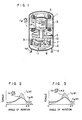
- reference numeral 1 designates a casing for storing therein motor elements and compression elements
- 2 a stator fixed to the casing 1
- 3 a rotor
- 4 a shaft pressed into and fixed to the rotor 3
- 5 a main bearing fixed to the casing 1 for supporting the shaft 4
- 6 an end bearing for supporting the shaft 4
- 7 a cylinder block held between the main bearing 5 and end bearing 6, 8 a roller fitted into a crank portion of the shaft 4
- 9 a vane for partitioning a cylinder chamber into a suction chamber 10 and a compression chamber 11, and 12 a vibration-proof member for supporting the compressor.
- Such a general, rotary compressor is described in U.S. Patent No. 3,130,902.
- a high-pressure gas in the compression chamber 11 produces counterclockwise load torque-T G ( ⁇ ) for the shaft 4, and produces clockwise torque T G ( ⁇ ) for the cylinder block 7.
- the torque T G ( ⁇ ) is determined mainly by a delivery pressure Pd and a suction pressure Ps.
- Fig. 2 shows relationships between the angle of rotation and each of the torque T G ( ⁇ ) and torque T M (6) at a period when the rotating portion is turned (or rotated) once. As shown in Fig.
- load torque T G ( ⁇ ) and motor output torque-T M ( ⁇ ) appear as the reaction of the load torque-T G ( ⁇ ) and motor output torque T M ( ⁇ ) at the rotating portion, and the torque difference T G ( ⁇ )-T M ( ⁇ ) appears similarly to the rotating portion.
- the torque difference T G ( ⁇ )-T M ( ⁇ ) is balanced by inertia torque which is produced when a non-rotational body having the moment of inertia J ST is turned so as to have an angular acceleration and restoring torque K. 8 which is produced when the vibration-proof member 12 is rotated by an angle 8.
- Fig. 3 shows a relationshiop among three quantities at a period when the rotating portion is turned once.
- the torque difference T G ( ⁇ )-T m ( ⁇ ) takes positive and negative values in a period when the rotating portion is turned once. That is, the torque difference acts as a vibration generating force, and the whole of the non-rotational body is rotated through an angle 8 (in other words, the non-rotational body vibrates).
- An object of the present invention is to provide an enclosed compressor which is free from vibration by making a difference between the load torque and motor output torque equal to zero, that is, by removing a vibration source in a conventional enclosed compressor.
- an asynchronous motor drives a compressor for a refrigerator and depending upon the temperature of the evaporator 20 in the refrigerator a phase shift is created via an electronic component 17 which changes the voltage (and hence the current) supplied to the asynchronous motor.
- the energy consumed by the motor can be made equal to the energy consumed by the compressor.
- the position of a rotational part of said compressor plays any role at all in controlling said phase shift during each revolution of the compressor and there is no evidence that the torque of the motor is made equal to the load torque on the compressor throughout each revolution.
- FIG. 4 designates a compressor, 14 a condenser, 15 a capillary tube, and 16 an evaporator. These parts 13 to 16 make up a refrigeration cycle. Further, in Fig.
- reference numerals 17-1 and 17-2 designate detectors for detecting information on a load applied to the compressor 13 (that is, a pressure on the delivery side), 18 a position detector for detecting the rotational position of the rotating portion of the compressor 13, 19 a signal converter for carrying out the analog-to- digital conversion for each of signals from the detectors 17-1, 17-2, and 18, and 20 a control unit formed of a microcomputer orthe like.
- Each of the detectors 17-1 and 17-2 is formed of a temperature sensor such as a thermistor.
- the position detector 18 is formed of, for instance, a rotary encoder.
- a temperature corresponding to the delivery pressure Pd is detected by the detector 17-1 and a temperature corresponding to the suction pressure Ps is detected by the detector 17-2 every moment.
- motor output torque corresponding to the torque T G thus calculated is calculated as a function of the rotational position of the motor, using position data from the position detector 18. Electric power supplied from a driving source 21 to the compressor 13 is adjusted in synchronism with a change in torque T G, on the basis of an instruction issued from the control unit 20.
- information on a load applied to the compressor 13 is detected by the detectors 17-1 and 17-2 which are provided on the parts included in the refrigeration cycle, and the rotational position of the rotating portion of the compressor 13 is detected by the position detector 18.
- Signals from the detectors 17-1, 17-2, and 18 are transferred to the control unit 20 through the signal converter 19.
- the magnitude of the load torque applied to the compressor 13 at rotational positions of said compressor during one revolution thereof is calculated by the control unit 20 on the basis of the above signals, and an instruction thus obtained is sent from the control unit 20 to the driving source 21 to control a voltage or current supplied to the compressor.
- the motor output torque T M ( ⁇ ) is made equal to the load torque T G ( ⁇ ) in synchronism with every change in load torque, and therefore the torque T M (A) and torque T G (G) are well-balanced. Accordingly, the vibration generating torque T G(8)- T M(8) is made equal to zero both on the rotating portion side and on the non-rotational side. That is, the vibration generating source is removed, and thus a vibration-free, enclosed compressor can be obtained.
- Fig. 5 shows another embodiment of a torque control apparatus for enclosed compressors according to the present invention.
- This embodiment has a function of controlling the rate of revolution of the rotating portion in addition to the function of controlling the motor output torque.
- like reference numerals designate like parts.
- reference numeral 17-3 designates a detector for detecting a temperature around the evaporator 16 to obtain information on a refrigerating capacity required for the compressor 13, 22 an inverter driving part, and 23 an inverter.
- the control unit 20 issues an instruction for controlling the inverter 23, on the basis of a signal from the detector 17-3, and thus the rate of revolution of the rotating portion is made correspond to the required refrigerating capacity to save electric power. That is, according to the present embodiment, the rate of revolution of the rotating portion and the load torque can be controlled in accordance with a load capacity, and thus an excellent enclosed compressor can be obtained which is small in power consumption and free from vibration.
- a voltage or current supplied to an enclosed compressor is controlled by a control system so that the motor output torque is made equal to the load torque in syncronism with every change in the load torque throughout each rotation of the rotating portion of the compressor, and therefore a difference between the load torque and motor output torque which acts as the vibration generating torque for the compressor, can be made equal to zero.
- a vibration-free, enclosed compressor can be obtained.
Landscapes
- Engineering & Computer Science (AREA)
- Mechanical Engineering (AREA)
- General Engineering & Computer Science (AREA)
- Physics & Mathematics (AREA)
- Thermal Sciences (AREA)
- General Physics & Mathematics (AREA)
- Automation & Control Theory (AREA)
- Control Of Positive-Displacement Pumps (AREA)
- Applications Or Details Of Rotary Compressors (AREA)
- Control Of Electric Motors In General (AREA)
- Control Of Motors That Do Not Use Commutators (AREA)
- Compressor (AREA)
Description
- The present invention relates to enclosed compressors, and more particularly to a torque control apparatus for enclosed compressors as set forth in the preamble of the appended
claim 1. - The structure of a conventional enclosed compressor will first be explained, with reference to Fig. 1. In Fig. 1,
reference numeral 1 designates a casing for storing therein motor elements and compression elements, 2 a stator fixed to thecasing 1, 3 a rotor, 4 a shaft pressed into and fixed to therotor 3, 5 a main bearing fixed to thecasing 1 for supporting theshaft shaft 4, 7 a cylinder block held between the main bearing 5 and end bearing 6, 8 a roller fitted into a crank portion of theshaft 4, 9 a vane for partitioning a cylinder chamber into asuction chamber 10 and a compression chamber 11, and 12 a vibration-proof member for supporting the compressor. Such a general, rotary compressor is described in U.S. Patent No. 3,130,902. - In the above-mentioned enclosed compressor, a high-pressure gas in the compression chamber 11 produces counterclockwise load torque-TG(θ) for the
shaft 4, and produces clockwise torque TG(θ) for thecylinder block 7. The torque TG(θ) is determined mainly by a delivery pressure Pd and a suction pressure Ps. - At a rotating portion including the
rotor 3 andshaft 4, the load torque-TG(θ) is balanced by the motor output torque TM(θ) given by thestator 2 and the inertia torque


- While, on the non-rotational side including the
stator 2,cylinder block 7, main bearing 5, and end bearing 6 each fixed to thecasing 1, load torque TG(θ) and motor output torque-TM(θ) appear as the reaction of the load torque-TG(θ) and motor output torque TM(θ) at the rotating portion, and the torque difference TG(θ)-TM(θ) appears similarly to the rotating portion. On the non-rotational side, however, the torque difference TG(θ)-TM(θ) is balanced by inertia torque

proof member 12 is rotated by anangle 8. The above-mentioned balance is expressed by an equation

- As mentioned above, in the conventional enclosed compressor, the torque difference TG(θ)-TM(θ) acting as a vibration source appears inevitably on the non-rotational side. Accordingly, no vibration-proof means can prevent the compressor from vibrating.
- An object of the present invention is to provide an enclosed compressor which is free from vibration by making a difference between the load torque and motor output torque equal to zero, that is, by removing a vibration source in a conventional enclosed compressor.
- In order to attain the above object, according to the present invention, the torque control apparatus defined in the introductory part of the description is provided with the features set forth in the characterizing portion of
claim 1, - In FR-A-2 347 819 an asynchronous motor drives a compressor for a refrigerator and depending upon the temperature of the
evaporator 20 in the refrigerator a phase shift is created via an electronic component 17 which changes the voltage (and hence the current) supplied to the asynchronous motor. By this means, it is stated, the energy consumed by the motor can be made equal to the energy consumed by the compressor. However, there is no disclosure in this prior art that the position of a rotational part of said compressor plays any role at all in controlling said phase shift during each revolution of the compressor and there is no evidence that the torque of the motor is made equal to the load torque on the compressor throughout each revolution. - The above mentioned object of the invention and other objects, features and advantages of the present invention will be apparent from the following detailed description of the preferred embodiments of the invention taken in conjunction with the accompanying drawings, in which:
- Fig. 1 is a sectional view showing the structure of a conventional enclosed compressor;
- Fig. 2 is a graph showing torque curves on the rotating portion side of the compressor shown in Fig. 1;
- Fig. 3 is a graph showing torque curves on the non-rotational side of the compressor shown in Fig. 1;
- Fig. 4 is a block diagram showing an embodiment of a torque control system for enclosed compressors according to the present invention; and
- Fig. 5 is a block diagram showing another embodiment of a torque control system for enclosed compressors according to the present invention.
- Now, explanation will be made on an embodiment of a torque control system for enclosed compressors according to the present invention, with reference to Fig. 4. In Fig. 4,
reference numeral 13 designates a compressor, 14 a condenser, 15 a capillary tube, and 16 an evaporator. Theseparts 13 to 16 make up a refrigeration cycle. Further, in Fig. 4, reference numerals 17-1 and 17-2 designate detectors for detecting information on a load applied to the compressor 13 (that is, a pressure on the delivery side), 18 a position detector for detecting the rotational position of the rotating portion of thecompressor 13, 19 a signal converter for carrying out the analog-to- digital conversion for each of signals from the detectors 17-1, 17-2, and 18, and 20 a control unit formed of a microcomputer orthe like. Each of the detectors 17-1 and 17-2 is formed of a temperature sensor such as a thermistor. Theposition detector 18 is formed of, for instance, a rotary encoder. - An equation TQ=(Pc-Ps) - S · T for determining the torque TG(θ) is previously stored in the control unit 20 (where Pc indicates a pressure in a cylinder depending upon the delivery pressure Pd, S is an area of the roller where the torque T is applied, and T is a distance between the center axis of the shaft and the point of action of a differential pressure), and the torque TG shown in Figs. 2 and 3 is calculated by the
control unit 20 on the basis of data with respect to the delivery pressure Pd and suction pressure Ps. A temperature corresponding to the delivery pressure Pd is detected by the detector 17-1 and a temperature corresponding to the suction pressure Ps is detected by the detector 17-2 every moment. Further, motor output torque corresponding to the torque TG thus calculated is calculated as a function of the rotational position of the motor, using position data from theposition detector 18. Electric power supplied from adriving source 21 to thecompressor 13 is adjusted in synchronism with a change in torque T G, on the basis of an instruction issued from thecontrol unit 20. - In the present embodiment having the above-mentioned construction, information on a load applied to the
compressor 13 is detected by the detectors 17-1 and 17-2 which are provided on the parts included in the refrigeration cycle, and the rotational position of the rotating portion of thecompressor 13 is detected by theposition detector 18. Signals from the detectors 17-1, 17-2, and 18 are transferred to thecontrol unit 20 through thesignal converter 19. The magnitude of the load torque applied to thecompressor 13 at rotational positions of said compressor during one revolution thereof is calculated by thecontrol unit 20 on the basis of the above signals, and an instruction thus obtained is sent from thecontrol unit 20 to thedriving source 21 to control a voltage or current supplied to the compressor. In thecompressor 13 thus controlled, throughout each rotation of the rotating portion of the compressor the motor output torque TM(θ) is made equal to the load torque TG(θ) in synchronism with every change in load torque, and therefore the torque TM(A) and torque TG(G) are well-balanced. Accordingly, the vibration generating torque T G(8)- T M(8) is made equal to zero both on the rotating portion side and on the non-rotational side. That is, the vibration generating source is removed, and thus a vibration-free, enclosed compressor can be obtained. - Fig. 5 shows another embodiment of a torque control apparatus for enclosed compressors according to the present invention. This embodiment has a function of controlling the rate of revolution of the rotating portion in addition to the function of controlling the motor output torque. In Figs. 4 and 5, like reference numerals designate like parts. In Fig. 5, reference numeral 17-3 designates a detector for detecting a temperature around the
evaporator 16 to obtain information on a refrigerating capacity required for thecompressor control unit 20 issues an instruction for controlling theinverter 23, on the basis of a signal from the detector 17-3, and thus the rate of revolution of the rotating portion is made correspond to the required refrigerating capacity to save electric power. That is, according to the present embodiment, the rate of revolution of the rotating portion and the load torque can be controlled in accordance with a load capacity, and thus an excellent enclosed compressor can be obtained which is small in power consumption and free from vibration. - As has been explained in the foregoing, according to the present invention, a voltage or current supplied to an enclosed compressor is controlled by a control system so that the motor output torque is made equal to the load torque in syncronism with every change in the load torque throughout each rotation of the rotating portion of the compressor, and therefore a difference between the load torque and motor output torque which acts as the vibration generating torque for the compressor, can be made equal to zero. Thus, a vibration-free, enclosed compressor can be obtained.
Claims (9)
Applications Claiming Priority (2)
| Application Number | Priority Date | Filing Date | Title |
|---|---|---|---|
| JP58164963A JPH0758069B2 (en) | 1983-09-09 | 1983-09-09 | Compressor motor controller |
| JP164963/83 | 1983-09-09 |
Publications (3)
| Publication Number | Publication Date |
|---|---|
| EP0145841A2 EP0145841A2 (en) | 1985-06-26 |
| EP0145841A3 EP0145841A3 (en) | 1985-07-24 |
| EP0145841B1 true EP0145841B1 (en) | 1989-11-08 |
Family
ID=15803194
Family Applications (1)
| Application Number | Title | Priority Date | Filing Date |
|---|---|---|---|
| EP84109884A Expired EP0145841B1 (en) | 1983-09-09 | 1984-08-20 | Torque control apparatus for enclosed compressors |
Country Status (6)
| Country | Link |
|---|---|
| US (1) | US4604036A (en) |
| EP (1) | EP0145841B1 (en) |
| JP (1) | JPH0758069B2 (en) |
| KR (1) | KR940004385B1 (en) |
| DE (1) | DE3480440D1 (en) |
| DK (1) | DK162408C (en) |
Families Citing this family (75)
| Publication number | Priority date | Publication date | Assignee | Title |
|---|---|---|---|---|
| US4726738A (en) * | 1985-01-16 | 1988-02-23 | Hitachi, Ltd. | Motor-driven compressor provided with torque control device |
| JPS61269693A (en) * | 1985-05-23 | 1986-11-29 | Mitsubishi Electric Corp | Controller of motor-driven compressor |
| JPH0742939B2 (en) * | 1985-10-07 | 1995-05-15 | 株式会社日立製作所 | Torque controlled compressor |
| US4860231A (en) * | 1985-12-16 | 1989-08-22 | Carrier Corporation | Calibration technique for variable speed motors |
| US4638898A (en) * | 1985-12-19 | 1987-01-27 | Eaton Corporation | Clutch control system and clutch assembly using same |
| JPH0822150B2 (en) * | 1986-08-13 | 1996-03-04 | 株式会社日立製作所 | Rotary electric machine with torque control |
| JPS6371590A (en) * | 1986-09-13 | 1988-03-31 | Daikin Ind Ltd | Vibration reducing device for rotary compressor |
| US4667480A (en) * | 1986-09-22 | 1987-05-26 | General Electric Company | Method and apparatus for controlling an electrically driven automotive air conditioner |
| JPH07122439B2 (en) * | 1986-12-09 | 1995-12-25 | ダイキン工業株式会社 | Vibration reduction device for rotary compressor |
| USRE33620E (en) * | 1987-02-09 | 1991-06-25 | Margaux, Inc. | Continuously variable capacity refrigeration system |
| DE69025898T2 (en) * | 1989-07-10 | 1996-11-14 | Sanyo Electric Co | METHOD AND ARRANGEMENT FOR CONTROLLING AN INDUCTION MOTOR FOR COMPRESSORS |
| JPH04156857A (en) * | 1990-10-19 | 1992-05-29 | Sharp Corp | Stepping motor control device for infusion pump |
| US5428965A (en) * | 1993-12-10 | 1995-07-04 | Whirlpool Corporation | Motor control for refrigeration appliance |
| US5516265A (en) * | 1994-06-14 | 1996-05-14 | Ingersoll-Rand Company | Interface apparatus for permitting microprocessor-based electronic control of non-electronically controlled air compressors |
| ES2247600T3 (en) * | 1995-06-07 | 2006-03-01 | Copeland Corporation | HELICOIDAL MODULATED CAPACITY MACHINE. |
| US5741120A (en) * | 1995-06-07 | 1998-04-21 | Copeland Corporation | Capacity modulated scroll machine |
| US5687050A (en) * | 1995-07-25 | 1997-11-11 | Ficht Gmbh | Electronic control circuit for an internal combustion engine |
| EP1141637A4 (en) | 1998-12-23 | 2004-03-31 | Mcdermott Will & Emery | COMPACT REFRIGERATOR |
| US6505475B1 (en) | 1999-08-20 | 2003-01-14 | Hudson Technologies Inc. | Method and apparatus for measuring and improving efficiency in refrigeration systems |
| JP2002362141A (en) * | 2001-01-09 | 2002-12-18 | Toyota Industries Corp | Air conditioner for vehicle |
| US6652239B2 (en) * | 2001-03-29 | 2003-11-25 | Kadant Inc. | Motor controller for a hydraulic pump with electrical regeneration |
| US6494685B2 (en) * | 2001-03-29 | 2002-12-17 | Kadant, Inc. | Pump and motor assembly with constant pressure output |
| US6668240B2 (en) | 2001-05-03 | 2003-12-23 | Emerson Retail Services Inc. | Food quality and safety model for refrigerated food |
| US6892546B2 (en) | 2001-05-03 | 2005-05-17 | Emerson Retail Services, Inc. | System for remote refrigeration monitoring and diagnostics |
| JP2003155981A (en) * | 2001-11-21 | 2003-05-30 | Toyota Industries Corp | Operation control method for vacuum pump and operation controller thereof |
| US6889762B2 (en) * | 2002-04-29 | 2005-05-10 | Bergstrom, Inc. | Vehicle air conditioning and heating system providing engine on and engine off operation |
| US9694651B2 (en) * | 2002-04-29 | 2017-07-04 | Bergstrom, Inc. | Vehicle air conditioning and heating system providing engine on and off operation |
| US20030214265A1 (en) | 2002-05-20 | 2003-11-20 | Vanderzee Joel C. | Stepper driver system with current feedback |
| US6889173B2 (en) * | 2002-10-31 | 2005-05-03 | Emerson Retail Services Inc. | System for monitoring optimal equipment operating parameters |
| WO2005022049A2 (en) | 2003-08-25 | 2005-03-10 | Computer Process Controls, Inc. | Refrigeration control system |
| US7412842B2 (en) | 2004-04-27 | 2008-08-19 | Emerson Climate Technologies, Inc. | Compressor diagnostic and protection system |
| US7275377B2 (en) | 2004-08-11 | 2007-10-02 | Lawrence Kates | Method and apparatus for monitoring refrigerant-cycle systems |
| ATE553422T1 (en) | 2005-02-21 | 2012-04-15 | Computer Process Controls Inc | CONTROL AND MONITORING SYSTEM FOR COMPANIES |
| US20060245961A1 (en) * | 2005-04-28 | 2006-11-02 | Tecumseh Products Company | Rotary compressor with permanent magnet motor |
| US7752854B2 (en) | 2005-10-21 | 2010-07-13 | Emerson Retail Services, Inc. | Monitoring a condenser in a refrigeration system |
| US7665315B2 (en) | 2005-10-21 | 2010-02-23 | Emerson Retail Services, Inc. | Proofing a refrigeration system operating state |
| US7596959B2 (en) | 2005-10-21 | 2009-10-06 | Emerson Retail Services, Inc. | Monitoring compressor performance in a refrigeration system |
| US7752853B2 (en) | 2005-10-21 | 2010-07-13 | Emerson Retail Services, Inc. | Monitoring refrigerant in a refrigeration system |
| US7594407B2 (en) | 2005-10-21 | 2009-09-29 | Emerson Climate Technologies, Inc. | Monitoring refrigerant in a refrigeration system |
| US20070261423A1 (en) * | 2006-05-15 | 2007-11-15 | Eddy Vanderee | Air conditioner |
| US8590325B2 (en) | 2006-07-19 | 2013-11-26 | Emerson Climate Technologies, Inc. | Protection and diagnostic module for a refrigeration system |
| US20080216494A1 (en) | 2006-09-07 | 2008-09-11 | Pham Hung M | Compressor data module |
| US8672733B2 (en) | 2007-02-06 | 2014-03-18 | Nordyne Llc | Ventilation airflow rate control |
| US8517087B2 (en) * | 2007-02-20 | 2013-08-27 | Bergstrom, Inc. | Combined heating and air conditioning system for vehicles |
| US8141377B2 (en) * | 2007-02-21 | 2012-03-27 | Bergstrom, Inc. | Truck electrified engine-off air conditioning system |
| WO2008105090A1 (en) * | 2007-02-28 | 2008-09-04 | Daikin Industries, Ltd. | Rotary compressor |
| US20090037142A1 (en) | 2007-07-30 | 2009-02-05 | Lawrence Kates | Portable method and apparatus for monitoring refrigerant-cycle systems |
| US9140728B2 (en) | 2007-11-02 | 2015-09-22 | Emerson Climate Technologies, Inc. | Compressor sensor module |
| US10100827B2 (en) * | 2008-07-28 | 2018-10-16 | Eaton Intelligent Power Limited | Electronic control for a rotary fluid device |
| WO2010138831A2 (en) | 2009-05-29 | 2010-12-02 | Emerson Retail Services, Inc. | System and method for monitoring and evaluating equipment operating parameter modifications |
| US8365544B2 (en) | 2009-08-20 | 2013-02-05 | Trane International Inc. | Screw compressor drive control |
| CA2828740C (en) | 2011-02-28 | 2016-07-05 | Emerson Electric Co. | Residential solutions hvac monitoring and diagnosis |
| US8964338B2 (en) | 2012-01-11 | 2015-02-24 | Emerson Climate Technologies, Inc. | System and method for compressor motor protection |
| US9310439B2 (en) | 2012-09-25 | 2016-04-12 | Emerson Climate Technologies, Inc. | Compressor having a control and diagnostic module |
| CN105531130B (en) | 2013-03-13 | 2019-05-31 | 博格思众公司 | Air Conditioning Systems Utilizing Heat Capacity from Compressed Fluid Expansion |
| EP3418089B1 (en) | 2013-03-13 | 2020-02-12 | Bergstrom, Inc. | Air conditioning system utilizing heat recovery ventilation for fresh air supply and climate control |
| US9803902B2 (en) | 2013-03-15 | 2017-10-31 | Emerson Climate Technologies, Inc. | System for refrigerant charge verification using two condenser coil temperatures |
| CA2904734C (en) | 2013-03-15 | 2018-01-02 | Emerson Electric Co. | Hvac system remote monitoring and diagnosis |
| US9551504B2 (en) | 2013-03-15 | 2017-01-24 | Emerson Electric Co. | HVAC system remote monitoring and diagnosis |
| AU2014248049B2 (en) | 2013-04-05 | 2018-06-07 | Emerson Climate Technologies, Inc. | Heat-pump system with refrigerant charge diagnostics |
| EP3065959B1 (en) | 2013-11-04 | 2020-06-10 | Bergstrom, Inc. | Low profile air conditioning system |
| US9783024B2 (en) | 2015-03-09 | 2017-10-10 | Bergstrom Inc. | System and method for remotely managing climate control systems of a fleet of vehicles |
| US10006684B2 (en) | 2015-12-10 | 2018-06-26 | Bergstrom, Inc. | Air conditioning system for use in vehicle |
| US9874384B2 (en) | 2016-01-13 | 2018-01-23 | Bergstrom, Inc. | Refrigeration system with superheating, sub-cooling and refrigerant charge level control |
| US10589598B2 (en) | 2016-03-09 | 2020-03-17 | Bergstrom, Inc. | Integrated condenser and compressor system |
| US12420616B2 (en) | 2016-08-22 | 2025-09-23 | Bergstrom, Inc. | Multi-compressor oil migration mitigation climate system |
| US10081226B2 (en) | 2016-08-22 | 2018-09-25 | Bergstrom Inc. | Parallel compressors climate system |
| US10562372B2 (en) | 2016-09-02 | 2020-02-18 | Bergstrom, Inc. | Systems and methods for starting-up a vehicular air-conditioning system |
| US10675948B2 (en) | 2016-09-29 | 2020-06-09 | Bergstrom, Inc. | Systems and methods for controlling a vehicle HVAC system |
| US10369863B2 (en) | 2016-09-30 | 2019-08-06 | Bergstrom, Inc. | Refrigerant liquid-gas separator with electronics cooling |
| US10724772B2 (en) | 2016-09-30 | 2020-07-28 | Bergstrom, Inc. | Refrigerant liquid-gas separator having an integrated check valve |
| US11448441B2 (en) | 2017-07-27 | 2022-09-20 | Bergstrom, Inc. | Refrigerant system for cooling electronics |
| US11420496B2 (en) | 2018-04-02 | 2022-08-23 | Bergstrom, Inc. | Integrated vehicular system for conditioning air and heating water |
| DE102018125999A1 (en) | 2018-10-19 | 2020-04-23 | OET GmbH | Method for controlling a scroll compressor and control device for a scroll compressor |
| DE102021128779A1 (en) | 2021-11-05 | 2023-05-11 | Vaillant Gmbh | Method for operating an electric motor of a compressor of a heat pump, computer program, storage medium, control unit and heat pump |
Family Cites Families (11)
| Publication number | Priority date | Publication date | Assignee | Title |
|---|---|---|---|---|
| US2985010A (en) * | 1957-06-12 | 1961-05-23 | Westinghouse Electric Corp | Shaft vibration responsive apparatus |
| US3130902A (en) * | 1961-08-28 | 1964-04-28 | Gen Electric | Refrigerator compressor |
| DE2429456A1 (en) * | 1974-06-19 | 1976-01-08 | Bosch Gmbh Robert | ROLLING PISTON COMPRESSOR |
| US4015182A (en) * | 1974-06-24 | 1977-03-29 | General Electric Company | Refrigeration system and control therefor |
| DE2437559A1 (en) * | 1974-08-03 | 1976-02-19 | Bosch Gmbh Robert | COMPRESSOR |
| DE2615768B2 (en) * | 1976-04-10 | 1978-04-20 | Bosch-Siemens Hausgeraete Gmbh, 7000 Stuttgart | Method for controlling the torque of an asynchronous motor |
| US4177649A (en) * | 1977-11-01 | 1979-12-11 | Borg-Warner Corporation | Surge suppression apparatus for compressor-driven system |
| FR2461126A1 (en) * | 1978-12-15 | 1981-01-30 | Gilson Medical Electronic Fran | PISTON PUMP WITH PRECISELY ADJUSTABLE FLOW |
| GB2060210B (en) * | 1979-10-11 | 1983-10-19 | Borg Warner | Surge suppression apparatus for compressor-driven system |
| JPS6012532B2 (en) * | 1980-10-13 | 1985-04-02 | 株式会社東芝 | Air conditioner control method |
| JPS5815494U (en) * | 1981-07-24 | 1983-01-31 | 株式会社東芝 | Electric motor control device |
-
1983
- 1983-09-09 JP JP58164963A patent/JPH0758069B2/en not_active Expired - Lifetime
-
1984
- 1984-08-17 DK DK396184A patent/DK162408C/en not_active IP Right Cessation
- 1984-08-17 US US06/641,675 patent/US4604036A/en not_active Expired - Lifetime
- 1984-08-20 DE DE8484109884T patent/DE3480440D1/en not_active Expired
- 1984-08-20 EP EP84109884A patent/EP0145841B1/en not_active Expired
- 1984-09-05 KR KR1019840005435A patent/KR940004385B1/en not_active Expired - Fee Related
Also Published As
| Publication number | Publication date |
|---|---|
| DK162408B (en) | 1991-10-21 |
| DE3480440D1 (en) | 1989-12-14 |
| KR850002874A (en) | 1985-05-20 |
| EP0145841A3 (en) | 1985-07-24 |
| US4604036A (en) | 1986-08-05 |
| JPH0758069B2 (en) | 1995-06-21 |
| DK396184A (en) | 1985-03-10 |
| DK396184D0 (en) | 1984-08-17 |
| KR940004385B1 (en) | 1994-05-23 |
| JPS6060286A (en) | 1985-04-06 |
| EP0145841A2 (en) | 1985-06-26 |
| DK162408C (en) | 1992-03-16 |
Similar Documents
| Publication | Publication Date | Title |
|---|---|---|
| US4604036A (en) | Torque control apparatus for enclosed compressors | |
| KR910009242B1 (en) | Torque Control of Rotary Motor | |
| JPH0742939B2 (en) | Torque controlled compressor | |
| US4723735A (en) | Energy storage attitude control and reference system | |
| US4726738A (en) | Motor-driven compressor provided with torque control device | |
| EP0823957B1 (en) | Auto reverse power closure system | |
| EP0900710B1 (en) | Electric power steering controller | |
| WO1991001062A1 (en) | Method of and device for controlling induction motor for compressor | |
| US5951269A (en) | Scroll compressor having well-balanced rotary elements | |
| JP2809182B2 (en) | Compressor motor controller | |
| EP0714323A1 (en) | Centrifuge rotor identification and refrigeration control system based on windage | |
| Ishii et al. | Mechanical efficiency of a variable speed scroll compressor | |
| JPH0340599B2 (en) | ||
| JPH0715994A (en) | Motor control device | |
| JP2853693B2 (en) | Refrigeration equipment | |
| JPS63290182A (en) | Torque control type rotary motor machine | |
| US5436544A (en) | Method of phase advancing compensation control for an AC synchronous motor | |
| JPS6173585A (en) | Torque control device for hermetic compressor | |
| RU2118796C1 (en) | Two-axle gyroscopic angular velocity meter with electric spring | |
| JPS61169916A (en) | Torque control type closed compressor | |
| KR910000097B1 (en) | Electric compressors with torque control | |
| JPS63219891A (en) | Rotary compressor rotation speed control method | |
| JPH0254315A (en) | Torque-controlled rotating electric machine | |
| JPS63147987A (en) | Vibration reducing device for rotary compressor | |
| JP2594451B2 (en) | Rotary electric machine with torque control |
Legal Events
| Date | Code | Title | Description |
|---|---|---|---|
| PUAI | Public reference made under article 153(3) epc to a published international application that has entered the european phase |
Free format text: ORIGINAL CODE: 0009012 |
|
| PUAL | Search report despatched |
Free format text: ORIGINAL CODE: 0009013 |
|
| 17P | Request for examination filed |
Effective date: 19840827 |
|
| AK | Designated contracting states |
Designated state(s): CH DE FR GB IT LI NL SE |
|
| AK | Designated contracting states |
Designated state(s): CH DE FR GB IT LI NL SE |
|
| 17Q | First examination report despatched |
Effective date: 19870421 |
|
| GRAA | (expected) grant |
Free format text: ORIGINAL CODE: 0009210 |
|
| AK | Designated contracting states |
Kind code of ref document: B1 Designated state(s): CH DE FR GB IT LI NL SE |
|
| PG25 | Lapsed in a contracting state [announced via postgrant information from national office to epo] |
Ref country code: SE Effective date: 19891108 Ref country code: LI Effective date: 19891108 Ref country code: CH Effective date: 19891108 |
|
| REF | Corresponds to: |
Ref document number: 3480440 Country of ref document: DE Date of ref document: 19891214 |
|
| ET | Fr: translation filed | ||
| ITF | It: translation for a ep patent filed | ||
| REG | Reference to a national code |
Ref country code: CH Ref legal event code: PL |
|
| PG25 | Lapsed in a contracting state [announced via postgrant information from national office to epo] |
Ref country code: GB Effective date: 19900820 |
|
| PLBE | No opposition filed within time limit |
Free format text: ORIGINAL CODE: 0009261 |
|
| STAA | Information on the status of an ep patent application or granted ep patent |
Free format text: STATUS: NO OPPOSITION FILED WITHIN TIME LIMIT |
|
| 26N | No opposition filed | ||
| GBPC | Gb: european patent ceased through non-payment of renewal fee | ||
| ITTA | It: last paid annual fee | ||
| PGFP | Annual fee paid to national office [announced via postgrant information from national office to epo] |
Ref country code: NL Payment date: 20030626 Year of fee payment: 20 |
|
| PGFP | Annual fee paid to national office [announced via postgrant information from national office to epo] |
Ref country code: FR Payment date: 20030715 Year of fee payment: 20 |
|
| PGFP | Annual fee paid to national office [announced via postgrant information from national office to epo] |
Ref country code: DE Payment date: 20030908 Year of fee payment: 20 |
|
| PG25 | Lapsed in a contracting state [announced via postgrant information from national office to epo] |
Ref country code: NL Free format text: LAPSE BECAUSE OF EXPIRATION OF PROTECTION Effective date: 20040820 |
|
| NLV7 | Nl: ceased due to reaching the maximum lifetime of a patent |