EP0145814B1 - Electronic stringed musical instrument - Google Patents
Electronic stringed musical instrument Download PDFInfo
- Publication number
- EP0145814B1 EP0145814B1 EP19830306525 EP83306525A EP0145814B1 EP 0145814 B1 EP0145814 B1 EP 0145814B1 EP 19830306525 EP19830306525 EP 19830306525 EP 83306525 A EP83306525 A EP 83306525A EP 0145814 B1 EP0145814 B1 EP 0145814B1
- Authority
- EP
- European Patent Office
- Prior art keywords
- string
- resistance
- voltage
- circuit
- tone
- Prior art date
- Legal status (The legal status is an assumption and is not a legal conclusion. Google has not performed a legal analysis and makes no representation as to the accuracy of the status listed.)
- Expired
Links
- 239000000463 material Substances 0.000 claims description 14
- 239000011295 pitch Substances 0.000 claims description 10
- 238000006243 chemical reaction Methods 0.000 claims description 9
- 230000001419 dependent effect Effects 0.000 claims description 9
- 230000000994 depressogenic effect Effects 0.000 claims description 9
- 238000004519 manufacturing process Methods 0.000 claims description 8
- 238000009413 insulation Methods 0.000 claims description 6
- 238000010586 diagram Methods 0.000 description 4
- 238000000034 method Methods 0.000 description 4
- 230000000694 effects Effects 0.000 description 3
- 239000004020 conductor Substances 0.000 description 2
- 238000011109 contamination Methods 0.000 description 2
- 239000002184 metal Substances 0.000 description 2
- 239000004593 Epoxy Substances 0.000 description 1
- 229910000831 Steel Inorganic materials 0.000 description 1
- 238000005299 abrasion Methods 0.000 description 1
- 230000003321 amplification Effects 0.000 description 1
- 230000002238 attenuated effect Effects 0.000 description 1
- 230000000881 depressing effect Effects 0.000 description 1
- 230000006866 deterioration Effects 0.000 description 1
- 230000005669 field effect Effects 0.000 description 1
- 239000012212 insulator Substances 0.000 description 1
- 230000004048 modification Effects 0.000 description 1
- 238000012986 modification Methods 0.000 description 1
- 238000003199 nucleic acid amplification method Methods 0.000 description 1
- 239000004033 plastic Substances 0.000 description 1
- 229920003023 plastic Polymers 0.000 description 1
- 238000003825 pressing Methods 0.000 description 1
- 239000011347 resin Substances 0.000 description 1
- 229920005989 resin Polymers 0.000 description 1
- 230000011218 segmentation Effects 0.000 description 1
- 229910001220 stainless steel Inorganic materials 0.000 description 1
- 239000010935 stainless steel Substances 0.000 description 1
- 239000010959 steel Substances 0.000 description 1
Images

Classifications
-
- G—PHYSICS
- G10—MUSICAL INSTRUMENTS; ACOUSTICS
- G10H—ELECTROPHONIC MUSICAL INSTRUMENTS; INSTRUMENTS IN WHICH THE TONES ARE GENERATED BY ELECTROMECHANICAL MEANS OR ELECTRONIC GENERATORS, OR IN WHICH THE TONES ARE SYNTHESISED FROM A DATA STORE
- G10H5/00—Instruments in which the tones are generated by means of electronic generators
- G10H5/002—Instruments using voltage controlled oscillators and amplifiers or voltage controlled oscillators and filters, e.g. Synthesisers
-
- G—PHYSICS
- G10—MUSICAL INSTRUMENTS; ACOUSTICS
- G10H—ELECTROPHONIC MUSICAL INSTRUMENTS; INSTRUMENTS IN WHICH THE TONES ARE GENERATED BY ELECTROMECHANICAL MEANS OR ELECTRONIC GENERATORS, OR IN WHICH THE TONES ARE SYNTHESISED FROM A DATA STORE
- G10H1/00—Details of electrophonic musical instruments
- G10H1/32—Constructional details
- G10H1/34—Switch arrangements, e.g. keyboards or mechanical switches specially adapted for electrophonic musical instruments
- G10H1/342—Switch arrangements, e.g. keyboards or mechanical switches specially adapted for electrophonic musical instruments for guitar-like instruments with or without strings and with a neck on which switches or string-fret contacts are used to detect the notes being played
-
- G—PHYSICS
- G10—MUSICAL INSTRUMENTS; ACOUSTICS
- G10H—ELECTROPHONIC MUSICAL INSTRUMENTS; INSTRUMENTS IN WHICH THE TONES ARE GENERATED BY ELECTROMECHANICAL MEANS OR ELECTRONIC GENERATORS, OR IN WHICH THE TONES ARE SYNTHESISED FROM A DATA STORE
- G10H3/00—Instruments in which the tones are generated by electromechanical means
- G10H3/12—Instruments in which the tones are generated by electromechanical means using mechanical resonant generators, e.g. strings or percussive instruments, the tones of which are picked up by electromechanical transducers, the electrical signals being further manipulated or amplified and subsequently converted to sound by a loudspeaker or equivalent instrument
- G10H3/14—Instruments in which the tones are generated by electromechanical means using mechanical resonant generators, e.g. strings or percussive instruments, the tones of which are picked up by electromechanical transducers, the electrical signals being further manipulated or amplified and subsequently converted to sound by a loudspeaker or equivalent instrument using mechanically actuated vibrators with pick-up means
- G10H3/18—Instruments in which the tones are generated by electromechanical means using mechanical resonant generators, e.g. strings or percussive instruments, the tones of which are picked up by electromechanical transducers, the electrical signals being further manipulated or amplified and subsequently converted to sound by a loudspeaker or equivalent instrument using mechanically actuated vibrators with pick-up means using a string, e.g. electric guitar
Definitions
- This invention relates to electronic stringed musical instruments and more specifically, to the use of resistance wires as strings which control the frequency of electronically generated sounds in such instruments.
- US-A-3,624,584 describes an arrangement in which the resistance in a Wien-bridge oscillator in an electrical circuit associated with a musical instrument is variable and US-A-3,626,350 discloses a means to produce a portamento chord by utilizing this principle.
- US-A-3,948,137 discloses an arrangement which allows the player of an instrument utilizing a voltage controlled oscillator to control sound effects by providing wave form, filter and gain controls.
- US-A-4,235,141 discloses an instrument wherein an apertured insulating strip is inserted between an electrically conducting strip and a resistive strip to allow only contact points at predetermined locations, thereby producing a tone at discrete selected values of frequency.
- Such a system has several major limitations. Firstly, the system is limited to fretted stringed instruments. Additionally, complicated wiring of resistors to each fret is required in order to provide each fret with the desired voltage value. Finally, providing the voltage to electrically conducting frets appears to foreclose the possibility of playing chords without fret segmentation.
- US-A-3742114 discloses a guitar-like stringed instrument which has electrically conductive strings suspended over a fingerboard the surface of which is provided by elongate strips of electrically resistive material, a respective said strip being provided for each string.
- a string is depressed to contact the respective resistive strip at a selected point, the portion of the strip between one end thereof and the point of contact forms a resistance connected in an electronic tone generating circuit, whereby a tone corresponding to the point of depression is produced.
- an electronic musical instrument comprising a body, a fingerboard attached to said body and having an upper surface, a plurality of strings arranged in spaced apart relationship relative to one another above said upper surface, the arrangement being such that each said string, when depressed to contact a portion of said upper surface immediately therebelow, forms, with the material affording the portion of said upper surface thus contacted, a resistance, incorporated in an electrical tone-determining circuit, which resistance is variable with the position at which the string contacts said upper surface, and which resistance determines the frequency of a corresponding electrical signal supplied by said tone-determining circuit to a corresponding sound production facility, characterised in that said upper surface of the fingerboard is electrically conductive and each said string is electrically resistive and is connected in a respective first electrical circuit with said fingerboard, which first electrical circuit forms part of the respective tone-determining circuit and is so devised as to provide an output voltage dependent on the resistance of the free length of the respective string, each said first electrical circuit being in turn connected with a respective voltage to frequency conversion
- an electronic musical instrument comprising a body, a fingerboard attached to said body and having an upper surface, a plurality of spaced strings arranged in spaced apart relationship relative to one another above said upper surface, the arrangement being such that each said string, when depressed to contact a portion of said upper surface immediately therebelow, forms, with the material affording the portion of said upper surface thus contacted, a resistance, incorporated in an electrical tone-determining circuit, which resistance is variable with the position at which the string contacts said upper surface, and which resistance determines the frequency of a corresponding electrical signal supplied by said tone-determining circuit to a corresponding sound production facility, characterised in that said upper surface of the fingerboard includes electrically conductive frets upstanding from the remainder of the fingerboard and each said string is electrically resistive and is connected in a respective first electrical circuit with said frets, which first electrical circuit forms part of the respective tone-determining circuit and is so devised as to provide an output voltage dependent on the resistance of the free length of the respective string, each said first
- an electronic musical instrument comprising a body, a fingerboard attached to said body and having an upper surface, a plurality of strings arranged in spaced apart relationship relative to one another above said upper surface, the arrangement being such that each said string, when depressed to contact a portion of said upper surface immediately therebelow, forms, with the material affording the portion of said upper surface thus contacted, a resistance, incorporated in an electrical tone-determining circuit, which resistance is variable with the position at which the string contacts said upper surface, and which resistance determines the frequency of a corresponding electrical signal supplied by said tone-determining circuit to a corresponding sound production facility, characterised in that said fingerboard has an electrically conducting upper surface, and in that each of said strings comprises a core, resistance wire insulated and generally tightly wound about and attached to said core, said insulation having been removed from an outer surface of said wound string, whereby displacing a string to contact said conductive surface at differing points along the string's length varies said resistance incorporated in said electrical tone-
- an electronic musical instrument comprising a body, a fingerboard attached to said body and having an upper surface, a plurality of strings arranged in spaced apart relationship relative to one another above said upper surface, the arrangement being such that each said string, when depressed to contact a portion of said upper surface immediately therebelow, forms, with the material affording the portion of said upper surface thus contacted, a resistance, incorporated in an electrical tone-determining circuit, which resistance is variable with the position at which the string contacts said upper surface, and which resistance determines the frequency of a corresponding electrical signal supplied by said tone-determining circuit to a corresponding sound production facility, characterised in that said fingerboard has an upper surface which is electrically insulating apart from a plurality of spaced conducting frets extending across the fingerboard at desired points along its length, and in that each of said strings comprises a core, resistance wire insulated and generally tightly wound about and attached to said core, said insulation having been removed from an outer surface of said wound string, whereby displacing a
- a variable voltage output that controls frequency is obtained by supplying a constant electrical current to each string, whereby depressing a string at various points along its length to contact the fingerboard or a respective fret thereon outputs a desired voltage.
- the output voltage depends upon the point along its length at which the string is shorted.
- the mode of shorting operation employed depends upon the type of stringed instrument. In a guitar or other fretted instrument the resistance strings can be shorted at any selected frets to provide a means to incrementally control the voltage output of the instrument. In a violin or other non-fretted instrument the resistance strings can be shorted at any point to the electrically conductive upper surface of the fingerboard to providing a means to control voltage output over a continuous range.
- each string is provided with a separate current source but all strings are referenced to the same grounding point.
- the frets or, in the case of a non-fretted instrument, the entire conducting surface of the neck are also grounded.
- the non-grounded end of each string is connected to a current source. The voltage drop produced when each string is grounded is detected so that the strings do not interfere with each other at the frets and consequently, chords can be played.
- means are provided for controlling the intensity and harmonic content of the signals produced. More specifically, suitable attenuators and filters that may be controlled by one of a player's hands while the other presses the strings to produce the desired frequency are provided. Wound resistance wire strings may be provided for low notes.
- an internal power supply and speaker may be provided to make the instrument readily portable.
- a frequency counter is integrated into the instrument's electrical circuit to facilitate tuning.
- string and strings refer to either straight or wound electrically conductive resistance wires and the terms “conducting” and “insulating” refer respectively to a material's capacity to conduct or to resist the conduction of an electrical current.
- the present invention provides a stringed musical instrument capable of varying the input voltage to an electrical circuit which converts the voltage to a frequency to produce a responsive musical tone.
- the instrument's strings provide resistance elements in the circuit. By urging a string against a conducting surface at different points along the string's length the circuit's resistance and the resulting voltage change can be effectively controlled and varied.
- the instrument 3 has a body 6 having any convenient shape and preferably is made of a rigid, electrically insulating, material.
- One end of a neck 9 is secured to the body by conventional means.
- the neck 9 is also preferably an insulator but both the neck and body may be conductors if desired.
- a rigid insulating fingerboard 12 is attached to the neck 9.
- a hardboard or rigid plastics material would be a suitable material to construct the fingerboard 12.
- An insulating bridge 15 is also so secured to the body 6, as to provide a means to elevate the strings a slight distance above the fingerboard 12.
- a plurality of conducting frets 16 are embedded across the fingerboard 12 at desired points along its length.
- the fret spacing may remain essentially the same as in regular guitars, and, as will be described further hereinafter, the current can be adjusted to correspond respective frets to the same notes as would be found in a conventional instrument.
- the frets 16 are preferably made from a hard conducting metal such as stainless steel.
- Embedded at the end of the fingerboard 12 farthest from the body 6 is a rigid conducting shorting bar 18 to support the strings a slight distance above the uppermost fret 16.
- the shorting bar 18 is electrically grounded.
- the frets 16 are electrically connected to one another and to the electrically grounded shorting bar 18 by a conductive connecting wire 30, as shown in Figures 1 and 2.
- the frets 16 may be connected together and to the shorting bar 18 by any other suitable means, such as by a conducting strip mounted under the insulating fingerboard 12 which contacts each of said frets 16 and the shorting bar 18.
- the strings (not shown) are attached to the instrument by conventional means and, as mentioned, are supported above the frets at one end by the insulating bridge 15 and at the other end by the shorting bar 18.
- the strings are tuned mechanically by adjusting their tension using appropriate tuning keys 26 in the usual fashion.
- Electronic tuning of each string is accomplished by turning a potentiometer knob 27 suitably wired into the circuit by conventional means.
- a frequency counter 33 may also be integrated into the circuit to facilitate tuning.
- a constant current power source and amplifier circuit 28 (also illustrated schematically in Figure 3) is connected to each string at or near the bridge 15 by any suitable means. It is preferable to make such connections at points 29 on the bridge 15 to avoid interference with the mechanical vibration of the strings. Points 29 may also serve as the input to an amplifier.
- an optional internal power supply 42 and speaker 45 could also be provided to make the instrument more portable.
- each string is maintained below 1000 ohms so that the changes in resistance due to finger contact do not play a perceptive role, unless such an effect is desired.
- Contacting a string to a chosen fret will complete an electrical circuit and create a desired voltage output which is then converted into a frequency signal by means well known in the art.
- Such voltage-to-frequency converters are now available as commercial integrated circuits.
- Means may also be provided for controlling the harmonic content and intensity .of the signals produced.
- the pitch or fundamental frequency is selected by means of a particular string. Harmonic frequencies are then selected by color control registers 39.
- the loudness can be effectively controlled in one of two ways.
- the strings may be plucked or banged as in conventional instruments.
- an electromagnetic pickup would be placed below each string as is done in conventional electric guitars.
- the output of the pickup 31 may then be amplified and rectified to derive the desired intensity envelope of the vibration, which is proportional to loudness.
- This loudness envelope voltage would then be used to control the loudness of the electronic sound by means of voltage controlled amplifiers.
- suitable pressure transducers 32 which can respond properly and rapidly to finger pressure, could be manipulated by the player's free hand to control loudness.
- the pressure transducers 32 could be in the form of buttons, perhaps one to control each string or any combination of strings.
- the voltage from these transducers would be applied through a voltage-controlled amplifier to control loudness.
- the separate control of the duration and loudness of each note in a chord thereby made possible by the use of this method, allows for greater flexibility and creative potential.
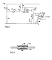
- FIG. 3 shows a schematic circuit diagram of a typical circuit to provide a suitable constant current source for this instrument and for first stage of amplification.
- a constant reference voltage -V is determined by means of a Zener diode 80 and a resistor 81.
- a resistor network R 3 , R 2 and R T apply a fraction of this voltage to the non-inverting input of an operational amplifier 82.
- the inverting input of the operational amplifier is connected to a resistor R 1 in which the voltage drop is proportional to the current Is which flows through a controlling field-effect transistor 83 and a string 84 with an effective resistance R s .
- the voltage drop over R s is I s R s .
- the resultant voltage, I S R 3 is fed to an operational amplifier 85, the gain of which may be adjusted by means of a variable control 86.
- Figure 4 represents a cross-sectional view of a string 79 wound with resistance wires that is suitable for producing low notes.
- the string 79 has a core of steel wire 75.
- a well insulated resistance wire 77 is tightly wound onto core wire 75.
- the whole string 79 has been dipped into a suitable resin (such as epoxy) to tightly fixate the insulation 78 in order to prevent electrical contact towards the core and between the turns of the resistance wire 77 that may result from abrasion due to internal flexing.
- the insulation 78 has been removed from an outer surface of the string, for example, by sanding, so that the string can make electrical contact with the frets 16.
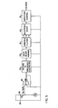
- FIG. 5 is a block diagram showing the various steps involved in one suitable method of converting voltage signals into frequency signals of desired wave characteristics.
- a string 39 is pressed to contact a fret 40 an electrical circuit is completed.
- the voltage signal is then amplified by the operational amplifier circuit 45 as shown.
- the amplified voltage signal obtained by the above described method is then converted into a frequency signal.
- the output frequency signal may be a sine wave or some other wave form.
- This output frqeuency signal may then be inputted into a wave shape former shown in block 55.
- the basic frequency signal may be filtered to remove undesired "harmonics" in the circuit as is indicated by block 60.
- Block 65 shows a selectable mixer which can be used to combine the frequency signals to produce various coloration of the sound. The output of the mixer is then attenuated as desired by a suitable circuit to control loudness, as shown by block 70.
Landscapes
- Physics & Mathematics (AREA)
- Engineering & Computer Science (AREA)
- Acoustics & Sound (AREA)
- Multimedia (AREA)
- Electrophonic Musical Instruments (AREA)
- Stringed Musical Instruments (AREA)
Description
- This invention relates to electronic stringed musical instruments and more specifically, to the use of resistance wires as strings which control the frequency of electronically generated sounds in such instruments.
- A variety of techniques are known for controlling the sound effects of electronic musical instruments. US-A-3,624,584 describes an arrangement in which the resistance in a Wien-bridge oscillator in an electrical circuit associated with a musical instrument is variable and US-A-3,626,350 discloses a means to produce a portamento chord by utilizing this principle.
- US-A-3,948,137 discloses an arrangement which allows the player of an instrument utilizing a voltage controlled oscillator to control sound effects by providing wave form, filter and gain controls.
- US-A-4,235,141 discloses an instrument wherein an apertured insulating strip is inserted between an electrically conducting strip and a resistive strip to allow only contact points at predetermined locations, thereby producing a tone at discrete selected values of frequency.
- Electrically synthesized music is becoming an increasingly popular art form and substantial technological advances have been made in this field. In the past, however, most of these advances could only be utilized in a keyboard type instrument and have not been available for musicians skilled primarily in the playing of stringed instruments.
- One attempt to provide a voltage controlled electronic stringed instrument is described in US-A-4,038,897. As described a guitar or other fretted instrument may be used to produce input signals for a voltage-controlled tone generator. Alternatively, the guitar may be used in the conventional fashion, the instrument being switchable between these two forms. Each string- fret pair has an assigned musical tone. Voltages analogous to said tones are applied to the frets and such voltage is applied to the strings when the strings are moved to contact the frets.
- Such a system has several major limitations. Firstly, the system is limited to fretted stringed instruments. Additionally, complicated wiring of resistors to each fret is required in order to provide each fret with the desired voltage value. Finally, providing the voltage to electrically conducting frets appears to foreclose the possibility of playing chords without fret segmentation.
- US-A-3742114 discloses a guitar-like stringed instrument which has electrically conductive strings suspended over a fingerboard the surface of which is provided by elongate strips of electrically resistive material, a respective said strip being provided for each string. When a string is depressed to contact the respective resistive strip at a selected point, the portion of the strip between one end thereof and the point of contact forms a resistance connected in an electronic tone generating circuit, whereby a tone corresponding to the point of depression is produced.
- However, the arrangement of US-A-3742114 presents various disadvantages. Thus, for example because the resistances defined by the portions of the resistive strips "tapped off" by the conductive strings are incorporated in the actual oscillator or tone generator circuits, it is necessary, for reasons which will be clear to those skilled in the art, for the resistances of the resistance strips to be relatively high for the instrument to be practicable, and this renders the tuning of the instrument sensitive to surface contamination of the resistive strips, for example by contamination with perspiration from the musician's fingers. Furthermore, the need to provide high values of resistance implies the use of either very thin metal conductors or deposits or of non-metallic resistive materials, with the result, in either case, that the resistance strips are relatively fragile. Furthermore, deterioration or modification of the resistive properties of the resistance strips for any of the above reasons can be rectified only by replacement of the resistance strips, which constitutes a major repair operation.
- It is an object of the present invention to provide a stringed electronic instrument in which the above disadvantages can be avoided, and which provides for effective frequency control in either fretted or unfretted string instruments and a means for playing chords whether or not frets are desired.
- According to one aspect of the invention, there is provided an electronic musical instrument comprising a body, a fingerboard attached to said body and having an upper surface, a plurality of strings arranged in spaced apart relationship relative to one another above said upper surface, the arrangement being such that each said string, when depressed to contact a portion of said upper surface immediately therebelow, forms, with the material affording the portion of said upper surface thus contacted, a resistance, incorporated in an electrical tone-determining circuit, which resistance is variable with the position at which the string contacts said upper surface, and which resistance determines the frequency of a corresponding electrical signal supplied by said tone-determining circuit to a corresponding sound production facility, characterised in that said upper surface of the fingerboard is electrically conductive and each said string is electrically resistive and is connected in a respective first electrical circuit with said fingerboard, which first electrical circuit forms part of the respective tone-determining circuit and is so devised as to provide an output voltage dependent on the resistance of the free length of the respective string, each said first electrical circuit being in turn connected with a respective voltage to frequency conversion means, forming a further part of the respective tone-determining circuit, and which serves to convertthe respective said output voltage into an electrical signal of a frequency dependent on said voltage, the instrument including transducer means for receiving said frequency signals and for producing sounds of corresponding pitch, whereby displacing a string to contact said conductive surface at differing points along the length of a string varies said resistance in the corresponding said first circuit to produce, via the respective said voltage to frequency conversion means, and the respective said transducer means, sounds of various pitches.
- According to a further aspect of the invention there is provided an electronic musical instrument comprising a body, a fingerboard attached to said body and having an upper surface, a plurality of spaced strings arranged in spaced apart relationship relative to one another above said upper surface, the arrangement being such that each said string, when depressed to contact a portion of said upper surface immediately therebelow, forms, with the material affording the portion of said upper surface thus contacted, a resistance, incorporated in an electrical tone-determining circuit, which resistance is variable with the position at which the string contacts said upper surface, and which resistance determines the frequency of a corresponding electrical signal supplied by said tone-determining circuit to a corresponding sound production facility, characterised in that said upper surface of the fingerboard includes electrically conductive frets upstanding from the remainder of the fingerboard and each said string is electrically resistive and is connected in a respective first electrical circuit with said frets, which first electrical circuit forms part of the respective tone-determining circuit and is so devised as to provide an output voltage dependent on the resistance of the free length of the respective string, each said first electrical circuit being in turn connected with a respective voltage to frequency conversion means, forming a further part of the respective tone-determining circuit, and which serves to convert the respective said output voltage into an electrical signal of a frequency dependent on said voltage, the instrument including transducer means for receiving said frequency signals and for producing sounds of corresponding pitch, whereby displacing a string to contact different said conductive frets at differing points along the length of a string varies said resistance in the corresponding said first circuit to produce, via the respective said voltage to frequency conversion means, and the respective said transducer means, sounds of various pitches.
- According to a yet further aspect of the invention, there is provided an electronic musical instrument comprising a body, a fingerboard attached to said body and having an upper surface, a plurality of strings arranged in spaced apart relationship relative to one another above said upper surface, the arrangement being such that each said string, when depressed to contact a portion of said upper surface immediately therebelow, forms, with the material affording the portion of said upper surface thus contacted, a resistance, incorporated in an electrical tone-determining circuit, which resistance is variable with the position at which the string contacts said upper surface, and which resistance determines the frequency of a corresponding electrical signal supplied by said tone-determining circuit to a corresponding sound production facility, characterised in that said fingerboard has an electrically conducting upper surface, and in that each of said strings comprises a core, resistance wire insulated and generally tightly wound about and attached to said core, said insulation having been removed from an outer surface of said wound string, whereby displacing a string to contact said conductive surface at differing points along the string's length varies said resistance incorporated in said electrical tone-determining circuit thereby providing a means to variably control the circuit's output voltage, and means for converting said output voltage into a predetermined frequency.
- According to a still further aspect of the invention, there is provided an electronic musical instrument comprising a body, a fingerboard attached to said body and having an upper surface, a plurality of strings arranged in spaced apart relationship relative to one another above said upper surface, the arrangement being such that each said string, when depressed to contact a portion of said upper surface immediately therebelow, forms, with the material affording the portion of said upper surface thus contacted, a resistance, incorporated in an electrical tone-determining circuit, which resistance is variable with the position at which the string contacts said upper surface, and which resistance determines the frequency of a corresponding electrical signal supplied by said tone-determining circuit to a corresponding sound production facility, characterised in that said fingerboard has an upper surface which is electrically insulating apart from a plurality of spaced conducting frets extending across the fingerboard at desired points along its length, and in that each of said strings comprises a core, resistance wire insulated and generally tightly wound about and attached to said core, said insulation having been removed from an outer surface of said wound string, whereby displacing a string selectively to contact differing frets along the string's length varies said resistance incorporated in said electrical tone-determining circuit thereby providing a means to incrementally control the circuit's output voltage, and means for converting said output voltage into a predetermined frequency.
- In preferred embodiments of the invention a variable voltage output that controls frequency is obtained by supplying a constant electrical current to each string, whereby depressing a string at various points along its length to contact the fingerboard or a respective fret thereon outputs a desired voltage. The output voltage depends upon the point along its length at which the string is shorted. The mode of shorting operation employed depends upon the type of stringed instrument. In a guitar or other fretted instrument the resistance strings can be shorted at any selected frets to provide a means to incrementally control the voltage output of the instrument. In a violin or other non-fretted instrument the resistance strings can be shorted at any point to the electrically conductive upper surface of the fingerboard to providing a means to control voltage output over a continuous range.
- Desirably, each string is provided with a separate current source but all strings are referenced to the same grounding point. The frets or, in the case of a non-fretted instrument, the entire conducting surface of the neck are also grounded. The non-grounded end of each string is connected to a current source. The voltage drop produced when each string is grounded is detected so that the strings do not interfere with each other at the frets and consequently, chords can be played.
- In the past, most voltage-controlled electronic instruments employed Wien-bridge oscillators or similar circuits which required relatively high resistance values for the control element. The preferred embodiment of the present invention, however, utilizes voltage-to-frequency converter circuit which can be controlled by relatively low resistance values as the respective voltages can be amplified before conversion, making possible the use of low resistance wires as the control elements. Furthermore, the high stability of the resistance, the constant current sources, and the precision of commercial voltage-to-frequency converters will make this instrument of professional quality.
- Preferably, means are provided for controlling the intensity and harmonic content of the signals produced. More specifically, suitable attenuators and filters that may be controlled by one of a player's hands while the other presses the strings to produce the desired frequency are provided. Wound resistance wire strings may be provided for low notes.
- Conveniently, an internal power supply and speaker may be provided to make the instrument readily portable.
- Desirably, a frequency counter is integrated into the instrument's electrical circuit to facilitate tuning.
- It is further contemplated that combining the electrical and mechanical string-produced sounds may have potential for expanding the instrument's artistic possibilities.
- In order that the invention may be more readily understood, and so that further features thereof may be appreciated, an embodiment of the invention will be described, by way of example, with reference to the accompanying drawings, in which:
- Figure 1 is a schematic view of one form of instrument of the invention including an electrically insulated fingerboard and conducting frets;
- Figure 2 is a cross-sectional view of the fingerboard shown in Figure 1 taken through the line 2-2 of Figure 1;
- Figure 3 is a schematic circuit diagram of a circuit to provide a suitable constant source for an instrument;
- Figure 4 is a cross-sectional view of a portion of a wound resistance wire string; and
- Figure 5 is a block diagram illustrating the various steps involved in converting changes in string resistance into frequency signals of desired quality characteristics.
- As used herein, in the absence of a clear, express indication to the contrary, the terms "string" and "strings" refer to either straight or wound electrically conductive resistance wires and the terms "conducting" and "insulating" refer respectively to a material's capacity to conduct or to resist the conduction of an electrical current.
- In summary, the present invention provides a stringed musical instrument capable of varying the input voltage to an electrical circuit which converts the voltage to a frequency to produce a responsive musical tone. The voltage (V) in the circuit is dependent upon two variables, current (I) and resistance (R) according to the relationship V=IR. It is preferred, but not required, to provide the instrument with a constant current source of power which results in a linear relationship between the voltage and resistance. The instrument's strings provide resistance elements in the circuit. By urging a string against a conducting surface at different points along the string's length the circuit's resistance and the resulting voltage change can be effectively controlled and varied.
- Referring more specifically to Figures 1 and 2 (wherein, for clarity of illustration, the strings have not been shown), one embodiment of the present invention in the form of a guitar type fretted instrument 3 is shown. The instrument 3 has a body 6 having any convenient shape and preferably is made of a rigid, electrically insulating, material. One end of a
neck 9 is secured to the body by conventional means. Theneck 9 is also preferably an insulator but both the neck and body may be conductors if desired. A rigidinsulating fingerboard 12 is attached to theneck 9. A hardboard or rigid plastics material would be a suitable material to construct thefingerboard 12. Aninsulating bridge 15 is also so secured to the body 6, as to provide a means to elevate the strings a slight distance above thefingerboard 12. - A plurality of conducting
frets 16 are embedded across thefingerboard 12 at desired points along its length. The fret spacing may remain essentially the same as in regular guitars, and, as will be described further hereinafter, the current can be adjusted to correspond respective frets to the same notes as would be found in a conventional instrument. The frets 16 are preferably made from a hard conducting metal such as stainless steel. Embedded at the end of thefingerboard 12 farthest from the body 6 is a rigidconducting shorting bar 18 to support the strings a slight distance above the uppermost fret 16. The shortingbar 18 is electrically grounded. - The frets 16 are electrically connected to one another and to the electrically grounded shorting
bar 18 by a conductive connectingwire 30, as shown in Figures 1 and 2. The frets 16 may be connected together and to the shortingbar 18 by any other suitable means, such as by a conducting strip mounted under the insulatingfingerboard 12 which contacts each of said frets 16 and the shortingbar 18. - The strings (not shown) are attached to the instrument by conventional means and, as mentioned, are supported above the frets at one end by the insulating
bridge 15 and at the other end by the shortingbar 18. The strings are tuned mechanically by adjusting their tension usingappropriate tuning keys 26 in the usual fashion. Electronic tuning of each string is accomplished by turning apotentiometer knob 27 suitably wired into the circuit by conventional means. Afrequency counter 33 may also be integrated into the circuit to facilitate tuning. - A constant current power source and amplifier circuit 28 (also illustrated schematically in Figure 3) is connected to each string at or near the
bridge 15 by any suitable means. It is preferable to make such connections at points 29 on thebridge 15 to avoid interference with the mechanical vibration of the strings. Points 29 may also serve as the input to an amplifier. - It is contemplated that an optional
internal power supply 42 andspeaker 45 could also be provided to make the instrument more portable. - Preferably, the resistance value of each string is maintained below 1000 ohms so that the changes in resistance due to finger contact do not play a perceptive role, unless such an effect is desired. Contacting a string to a chosen fret will complete an electrical circuit and create a desired voltage output which is then converted into a frequency signal by means well known in the art. Such voltage-to-frequency converters are now available as commercial integrated circuits.
- It will be appreciated by those skilled in the art that by eliminating the frets and replacing or covering the insulating fingerboard with a sheet- like conducting fingerboard, a violin type non-fretted instrument will function essentially as described above. With this embodiment continuous variability of pitch can be achieved.
- Means may also be provided for controlling the harmonic content and intensity .of the signals produced. First, the pitch or fundamental frequency is selected by means of a particular string. Harmonic frequencies are then selected by color control registers 39.
- It is contemplated that the loudness can be effectively controlled in one of two ways. In one embodiment, the strings may be plucked or banged as in conventional instruments. In this case an electromagnetic pickup would be placed below each string as is done in conventional electric guitars. The output of the
pickup 31 may then be amplified and rectified to derive the desired intensity envelope of the vibration, which is proportional to loudness. This loudness envelope voltage would then be used to control the loudness of the electronic sound by means of voltage controlled amplifiers. - In an alternative embodiment
suitable pressure transducers 32, which can respond properly and rapidly to finger pressure, could be manipulated by the player's free hand to control loudness. The pressure transducers 32 could be in the form of buttons, perhaps one to control each string or any combination of strings. The voltage from these transducers would be applied through a voltage-controlled amplifier to control loudness. The separate control of the duration and loudness of each note in a chord thereby made possible by the use of this method, allows for greater flexibility and creative potential. - Figure 3 shows a schematic circuit diagram of a typical circuit to provide a suitable constant current source for this instrument and for first stage of amplification. A constant reference voltage -V= is determined by means of a
Zener diode 80 and aresistor 81. A resistor network R3, R2 and RT apply a fraction of this voltage to the non-inverting input of anoperational amplifier 82. The inverting input of the operational amplifier is connected to a resistor R1 in which the voltage drop is proportional to the current Is which flows through a controlling field-effect transistor 83 and a string 84 with an effective resistance Rs. The voltage drop over Rs is IsRs. The resultant voltage, ISR3, is fed to anoperational amplifier 85, the gain of which may be adjusted by means of avariable control 86. The value of the constant current Is can be adjusted by means of atuning control 87 through the relationship Is=VzRiR1(R2+R3+RT). - Figure 4 represents a cross-sectional view of a string 79 wound with resistance wires that is suitable for producing low notes. The string 79 has a core of steel wire 75. A well
insulated resistance wire 77 is tightly wound onto core wire 75. The whole string 79 has been dipped into a suitable resin (such as epoxy) to tightly fixate the insulation 78 in order to prevent electrical contact towards the core and between the turns of theresistance wire 77 that may result from abrasion due to internal flexing. The insulation 78 has been removed from an outer surface of the string, for example, by sanding, so that the string can make electrical contact with the frets 16. - Figure 5 is a block diagram showing the various steps involved in one suitable method of converting voltage signals into frequency signals of desired wave characteristics. As a
string 39 is pressed to contact a fret 40 an electrical circuit is completed. The resistance of the portion of the string now included in the circuit will alter the voltage in the circuit according to V=IR. By pressing the string to contact other frets (not shown) different voltage outputs can be obtained. The voltage signal is then amplified by theoperational amplifier circuit 45 as shown. As indicated in block 50 of Figure 5, the amplified voltage signal obtained by the above described method is then converted into a frequency signal. Depending on the type of voltage-to-frequency converter employed the output frequency signal may be a sine wave or some other wave form. This output frqeuency signal may then be inputted into a wave shape former shown in block 55. After a desired wave form is obtained, the basic frequency signal may be filtered to remove undesired "harmonics" in the circuit as is indicated by block 60. Block 65 shows a selectable mixer which can be used to combine the frequency signals to produce various coloration of the sound. The output of the mixer is then attenuated as desired by a suitable circuit to control loudness, as shown by block 70.
Claims (13)
Priority Applications (2)
| Application Number | Priority Date | Filing Date | Title |
|---|---|---|---|
| EP19830306525 EP0145814B1 (en) | 1983-10-26 | 1983-10-26 | Electronic stringed musical instrument |
| DE8383306525T DE3377953D1 (en) | 1983-10-26 | 1983-10-26 | Electronic stringed musical instrument |
Applications Claiming Priority (1)
| Application Number | Priority Date | Filing Date | Title |
|---|---|---|---|
| EP19830306525 EP0145814B1 (en) | 1983-10-26 | 1983-10-26 | Electronic stringed musical instrument |
Publications (2)
| Publication Number | Publication Date |
|---|---|
| EP0145814A1 EP0145814A1 (en) | 1985-06-26 |
| EP0145814B1 true EP0145814B1 (en) | 1988-09-07 |
Family
ID=8191330
Family Applications (1)
| Application Number | Title | Priority Date | Filing Date |
|---|---|---|---|
| EP19830306525 Expired EP0145814B1 (en) | 1983-10-26 | 1983-10-26 | Electronic stringed musical instrument |
Country Status (2)
| Country | Link |
|---|---|
| EP (1) | EP0145814B1 (en) |
| DE (1) | DE3377953D1 (en) |
Family Cites Families (4)
| Publication number | Priority date | Publication date | Assignee | Title |
|---|---|---|---|---|
| FR2039534A5 (en) * | 1969-04-02 | 1971-01-15 | Woltz Rene | |
| US3673304A (en) * | 1970-11-13 | 1972-06-27 | Raymond Lee Organization Inc | Electronic guitar having plural output channels, one of which simulates an organ |
| US3742114A (en) * | 1971-07-22 | 1973-06-26 | R Barkan | Guitar-like electronic musical instrument using resistor strips and potentiometer means to activate tone generators |
| US4306480A (en) * | 1977-03-29 | 1981-12-22 | Frank Eventoff | Electronic musical instrument |
-
1983
- 1983-10-26 EP EP19830306525 patent/EP0145814B1/en not_active Expired
- 1983-10-26 DE DE8383306525T patent/DE3377953D1/en not_active Expired
Also Published As
| Publication number | Publication date |
|---|---|
| EP0145814A1 (en) | 1985-06-26 |
| DE3377953D1 (en) | 1988-10-13 |
Similar Documents
| Publication | Publication Date | Title |
|---|---|---|
| US4430918A (en) | Electronic musical instrument | |
| US4658690A (en) | Electronic musical instrument | |
| US3742114A (en) | Guitar-like electronic musical instrument using resistor strips and potentiometer means to activate tone generators | |
| US3767833A (en) | Electronic musical instrument | |
| US4038897A (en) | Electronic music system and stringed instrument input device therefor | |
| JP6089284B2 (en) | Stringed instrument, system and method using apparatus similar to stringed instrument | |
| CN105917403B (en) | Method and apparatus for using low inductance coils in electronic pickups | |
| US3742113A (en) | Stringed musical instrument with electrical feedback | |
| US4580479A (en) | Guitar controller | |
| JPS5913749B2 (en) | stringless electronic musical instrument | |
| US6800797B2 (en) | Method and apparatus for producing acoustical guitar sounds using an electric guitar | |
| US6372973B1 (en) | Musical instruments that generate notes according to sounds and manually selected scales | |
| EP0173006A1 (en) | Segmented fret electronic musical instrument | |
| US4171659A (en) | Electrified guitar accessory | |
| US2201232A (en) | Electrical musical instrument | |
| US3178501A (en) | Controls for electrical string instruments | |
| US3223771A (en) | Electronic musical instrument employing finger-pressure means to sequentially energize oscillator means and amplifier means | |
| US4677419A (en) | Electronic musical instrument | |
| US4676134A (en) | Electronic string instrument with bend detector | |
| US4621557A (en) | Electronic musical instrument | |
| US5990411A (en) | Methods for utilizing switches on the back of the neck of a musical instrument | |
| US20020069747A1 (en) | String station assembly | |
| EP0145814A1 (en) | Electronic stringed musical instrument | |
| CA1216182A (en) | Electronic musical instrument | |
| JPS60154297A (en) | Electronic musical instrument |
Legal Events
| Date | Code | Title | Description |
|---|---|---|---|
| PUAI | Public reference made under article 153(3) epc to a published international application that has entered the european phase |
Free format text: ORIGINAL CODE: 0009012 |
|
| AK | Designated contracting states |
Designated state(s): BE DE FR GB IT NL |
|
| 17P | Request for examination filed |
Effective date: 19851018 |
|
| 17Q | First examination report despatched |
Effective date: 19870130 |
|
| GRAA | (expected) grant |
Free format text: ORIGINAL CODE: 0009210 |
|
| AK | Designated contracting states |
Kind code of ref document: B1 Designated state(s): BE DE FR GB IT NL |
|
| PG25 | Lapsed in a contracting state [announced via postgrant information from national office to epo] |
Ref country code: NL Effective date: 19880907 Ref country code: IT Free format text: LAPSE BECAUSE OF FAILURE TO SUBMIT A TRANSLATION OF THE DESCRIPTION OR TO PAY THE FEE WITHIN THE PRESCRIBED TIME-LIMIT;WARNING: LAPSES OF ITALIAN PATENTS WITH EFFECTIVE DATE BEFORE 2007 MAY HAVE OCCURRED AT ANY TIME BEFORE 2007. THE CORRECT EFFECTIVE DATE MAY BE DIFFERENT FROM THE ONE RECORDED. Effective date: 19880907 Ref country code: BE Effective date: 19880907 |
|
| REF | Corresponds to: |
Ref document number: 3377953 Country of ref document: DE Date of ref document: 19881013 |
|
| ET | Fr: translation filed | ||
| NLV1 | Nl: lapsed or annulled due to failure to fulfill the requirements of art. 29p and 29m of the patents act | ||
| PLBE | No opposition filed within time limit |
Free format text: ORIGINAL CODE: 0009261 |
|
| STAA | Information on the status of an ep patent application or granted ep patent |
Free format text: STATUS: NO OPPOSITION FILED WITHIN TIME LIMIT |
|
| 26N | No opposition filed | ||
| PGFP | Annual fee paid to national office [announced via postgrant information from national office to epo] |
Ref country code: FR Payment date: 19941011 Year of fee payment: 12 |
|
| PGFP | Annual fee paid to national office [announced via postgrant information from national office to epo] |
Ref country code: GB Payment date: 19941018 Year of fee payment: 12 |
|
| PGFP | Annual fee paid to national office [announced via postgrant information from national office to epo] |
Ref country code: DE Payment date: 19941021 Year of fee payment: 12 |
|
| PG25 | Lapsed in a contracting state [announced via postgrant information from national office to epo] |
Ref country code: GB Effective date: 19951026 |
|
| GBPC | Gb: european patent ceased through non-payment of renewal fee |
Effective date: 19951026 |
|
| PG25 | Lapsed in a contracting state [announced via postgrant information from national office to epo] |
Ref country code: FR Effective date: 19960628 |
|
| PG25 | Lapsed in a contracting state [announced via postgrant information from national office to epo] |
Ref country code: DE Effective date: 19960702 |
|
| REG | Reference to a national code |
Ref country code: FR Ref legal event code: ST |