EP0145295B1 - Apparatus for winding metal strip - Google Patents
Apparatus for winding metal strip Download PDFInfo
- Publication number
- EP0145295B1 EP0145295B1 EP19840307793 EP84307793A EP0145295B1 EP 0145295 B1 EP0145295 B1 EP 0145295B1 EP 19840307793 EP19840307793 EP 19840307793 EP 84307793 A EP84307793 A EP 84307793A EP 0145295 B1 EP0145295 B1 EP 0145295B1
- Authority
- EP
- European Patent Office
- Prior art keywords
- strip
- roll
- wrapper
- mandrel
- rolls
- Prior art date
- Legal status (The legal status is an assumption and is not a legal conclusion. Google has not performed a legal analysis and makes no representation as to the accuracy of the status listed.)
- Expired
Links
Images
Classifications
-
- B—PERFORMING OPERATIONS; TRANSPORTING
- B21—MECHANICAL METAL-WORKING WITHOUT ESSENTIALLY REMOVING MATERIAL; PUNCHING METAL
- B21C—MANUFACTURE OF METAL SHEETS, WIRE, RODS, TUBES, PROFILES OR LIKE SEMI-MANUFACTURED PRODUCTS OTHERWISE THAN BY ROLLING; AUXILIARY OPERATIONS USED IN CONNECTION WITH METAL-WORKING WITHOUT ESSENTIALLY REMOVING MATERIAL
- B21C47/00—Winding-up, coiling or winding-off metal wire, metal band or other flexible metal material characterised by features relevant to metal processing only
- B21C47/02—Winding-up or coiling
- B21C47/04—Winding-up or coiling on or in reels or drums, without using a moving guide
- B21C47/06—Winding-up or coiling on or in reels or drums, without using a moving guide with loaded rollers, bolts, or equivalent means holding the material on the reel or drum
- B21C47/063—Winding-up or coiling on or in reels or drums, without using a moving guide with loaded rollers, bolts, or equivalent means holding the material on the reel or drum with pressure rollers only
Definitions
- This invention relates to an apparatus for winding strip metal, and in particular one in which the strip is guided onto a mandrel or the like by two or more wrapper rolls.
- wrapper rolls it is well known to use wrapper rolls to guide metal strip round a mandrel while the first few turns are coiled. Once the coil is established the wrapper rolls are withdrawn and the mandrel expanded slightly to grip the coil. A problem arises during those first turns when the leading edge of the strip passes under the wrapper rolls and the strip is damaged by the rolls hammering the strip. The hammering occurs even when the leading edge is overlaid by the coiled strip because the overlying strip is deformed into a step adjacent the leading edge. Thus, damage can be caused over the whole period of the wrapper roll engagement and therefore be costly.
- One aspect of the invention provides a coilerfor metal strip which has a coiler mandrel, at least three wrapper rolls spaced about the mandrel for guiding the initial wraps of a coil about the mandrel, and actuating means for each of the wrapper rolls for urging the respective roll into engagement with the strip, or for displacing that roll outwardly; and for each wrapper roll, associated sensing means for producing an output signal on the passage of the leading end of the strip past a given location, characterised by means responsive to the output signal for operating immediately the actuating means of the adjacent wrapper roll in the opposite direction to rotation of the mandrel, to displace that wrapper roll away from the mandrel.
- leading edge should be considered to cover not only that edge alone but also that edge as overlayed during coiling process.
- Another aspect of the invention provides a method of coiling metal strip on a coiler which has a coiler mandrel, at least three wrapper rolls spaced about the mandrel for guiding the initial wraps of a coil about the mandrel, and actuating means for each of the wrapper rolls for urging the respective roll into engagement with the strip and for displacing that roll outwardly, the method comprising:
- an apparatus for winding metal strip 10 includes a mandrel 1 for receiving the strip 10 and wrapper rolls 2, 3 and 4 for guiding the strip about the mandrel.
- Each wrapper roll has a respective double-acting hydraulic ram 5, 6 or 7, which, in use, presses the associated wrapper roll 2, 3 or 4 the strip 10 into the mandrel 1 to coil the strip.
- Guide plates 9 are provided about the mandrel, to assist in the guidance of the strip.
- a set of pinch rolls 8 is arranged to feed the strip 10 to the mandrel.
- each of the hydraulic rams 5, 6 and 7 has a respective sensor 11, 12 or 13 arranged to sense the hydraulic pressure'in that ram, and in particular to sense any rise in that pressure.
- the sensors 11, 12 and 13 are each connected with a control unit 5a, 6a, 7a, of an adjacent ram; in particular each sensor 11, 12, and 13 is connected with the control unit of the last ram in the advance direction of strip travel next to the roll with that particular sensor, or in other words, adjacent the ram in the opposite direction to the mandrel rotation (strip travel) i.e. the sensor at 11 is connected with the control unit 7a, the sensor 12 with control unit 5a, and the sensor at 13 with the ram control unit 6a.
- the wrapper rolls at 2 and 3 are displaced from the mandrel an amount slightly less than the thickness of the strip to be coiled, and the wrapper roll at 4 is left in contact or thereabouts with the mandrel.
- the strip 10 is fed to the mandrel 1 from pinch rolls 8 and engages the wrapper roll 2, urging that roll outwards.
- the strip is held between the wrapper roll at 2 and the mandrel 1 and the sensor 11 senses the increase in pressure in the hydraulic ram 5.
- the sensor provides a signal to the control unit 7a so that the ram 7 can displace the wrapper roll 4 outwards by an amount slightly less than the strip thickness.
- the sensor 12 provides a signal to the control unit 5a so that the ram 5 displaces the wrapper roll 2 outwards.
- the sensor 13 signals to the control unit 6a so that the ram 6 displaces the wrapper roll 3 outwards.
- pressure sensor may be used to sense the outward displacement of the wrapper rolls
- accelerometers could be mounted on the roll carrying frame to sense the outward acceleration of the wrapper rolls when engaged by the leading edge or step in the strip.
- each of the wrapper rolls 2, and 4 mounteded on the frame of each of the wrapper rolls 2, and 4 is a respective sensor roll 16, 17 and 18.
- Each sensor roll is a comparatively light roll which is arranged to engage the strip 10 and be displaced bythe leading edge orthe step in the strip, and to respond to the displacement so that the signal indicative the leading edge or step is produced, e.g. by an accelerometer or pressure sensor which is connected to the sensor roll.
- the sensor rolls 16,17 and 18 are designed not to press the strip into engagement with the mandrel.
- one of the sensor rolls senses the passage of the leading edge or step in the strip
- a control signal is produced and the associated wrapper roll is displaced outwards before the edge of the strip reaches that roll.
- the wrapper roll can remain outwardly displaced for a predetermined time sufficient for the leading edge to pass the roll and then be returned to engage with the strip.
Landscapes
- Engineering & Computer Science (AREA)
- Mechanical Engineering (AREA)
- Registering, Tensioning, Guiding Webs, And Rollers Therefor (AREA)
- Winding, Rewinding, Material Storage Devices (AREA)
- Controlling Rewinding, Feeding, Winding, Or Abnormalities Of Webs (AREA)
- Winding Of Webs (AREA)
Description
- This invention relates to an apparatus for winding strip metal, and in particular one in which the strip is guided onto a mandrel or the like by two or more wrapper rolls.
- It is well known to use wrapper rolls to guide metal strip round a mandrel while the first few turns are coiled. Once the coil is established the wrapper rolls are withdrawn and the mandrel expanded slightly to grip the coil. A problem arises during those first turns when the leading edge of the strip passes under the wrapper rolls and the strip is damaged by the rolls hammering the strip. The hammering occurs even when the leading edge is overlaid by the coiled strip because the overlying strip is deformed into a step adjacent the leading edge. Thus, damage can be caused over the whole period of the wrapper roll engagement and therefore be costly.
- It is known, see e.g. US-A-4,380,164, to outwardly displace a wrapper roll just in advance of the leading edge of the strip, and to return that roll into engagement with the strip after passage of the leading edge.
- One aspect of the invention provides a coilerfor metal strip which has a coiler mandrel, at least three wrapper rolls spaced about the mandrel for guiding the initial wraps of a coil about the mandrel, and actuating means for each of the wrapper rolls for urging the respective roll into engagement with the strip, or for displacing that roll outwardly; and for each wrapper roll, associated sensing means for producing an output signal on the passage of the leading end of the strip past a given location, characterised by means responsive to the output signal for operating immediately the actuating means of the adjacent wrapper roll in the opposite direction to rotation of the mandrel, to displace that wrapper roll away from the mandrel.
- It is intended that the term "leading edge" should be considered to cover not only that edge alone but also that edge as overlayed during coiling process.
- Another aspect of the invention provides a method of coiling metal strip on a coiler which has a coiler mandrel, at least three wrapper rolls spaced about the mandrel for guiding the initial wraps of a coil about the mandrel, and actuating means for each of the wrapper rolls for urging the respective roll into engagement with the strip and for displacing that roll outwardly, the method comprising:
- (a) positioning the wrapper rolls adjacent the coiler mandrel for engaging the strip;
- (b) feeding strip towards the coiler mandrel and wrapper rolls;
- (c) sensing the passage of the strip past a given point; and characterised by the step of;
- (d) controlling the actuating means of an adjacent wrapper roll in the opposite direction to rotation of the mandrel, immediately passage of the strip is sensed, to displace that adjacent wrapper roll away from the mandrel.
- Preferred embodiments of the invention will now be described with reference to the accompanying drawings, wherein:
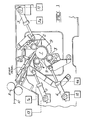
- Figure 1 is a schematic elevation of one embodiment; and
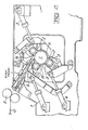
- Figure 2 is a schematic elevation of another embodiment.
- Refering to the drawings, an apparatus for
winding metal strip 10 includes amandrel 1 for receiving thestrip 10 and wrapper rolls 2, 3 and 4 for guiding the strip about the mandrel. Each wrapper roll has a respective double-actinghydraulic ram 5, 6 or 7, which, in use, presses the associated wrapper roll 2, 3 or 4 thestrip 10 into themandrel 1 to coil the strip.Guide plates 9 are provided about the mandrel, to assist in the guidance of the strip. A set ofpinch rolls 8 is arranged to feed thestrip 10 to the mandrel. - Referring now to Figure 1, each of the
hydraulic rams 5, 6 and 7 has arespective sensor sensors control unit 5a, 6a, 7a, of an adjacent ram; in particular eachsensor sensor 12 withcontrol unit 5a, and the sensor at 13 with the ram control unit 6a. - In use, the wrapper rolls at 2 and 3 are displaced from the mandrel an amount slightly less than the thickness of the strip to be coiled, and the wrapper roll at 4 is left in contact or thereabouts with the mandrel. The
strip 10 is fed to themandrel 1 frompinch rolls 8 and engages the wrapper roll 2, urging that roll outwards. The strip is held between the wrapper roll at 2 and themandrel 1 and thesensor 11 senses the increase in pressure in thehydraulic ram 5. The sensor provides a signal to the control unit 7a so that the ram 7 can displace the wrapper roll 4 outwards by an amount slightly less than the strip thickness. Similarly, when the leading edge of thestrip 10 has progressed sufficiently to engage with the wrapper roll at 3, thesensor 12 provides a signal to thecontrol unit 5a so that theram 5 displaces the wrapper roll 2 outwards. Again, when the leading edge of thestrip 10 reaches and engages the wrapper roll 4, thesensor 13 signals to the control unit 6a so that the ram 6 displaces the wrapper roll 3 outwards. - The process of outward displacement of a wrapper roll continues until the stage where the wrapper rolls are completely removed.
- It will be appreciated that by successively displacing rolls outwards by slightly less than the strip thickness the effect of hammering when each roll engages the strip is greatly reduced. The strip is still held in engagement with the mandrel by at least one wrapper roll.
- Other means than the pressure sensor may be used to sense the outward displacement of the wrapper rolls, for example, accelerometers could be mounted on the roll carrying frame to sense the outward acceleration of the wrapper rolls when engaged by the leading edge or step in the strip.
- Referring now to Figure 2, in another embodiment the arrangement of
mandrel 1 wrapper rolls 2, 3 and 4, andhydraulic rams 5, 6 and 7 is as already described. Mounted on the frame of each of the wrapper rolls 2, and 4 is arespective sensor roll strip 10 and be displaced bythe leading edge orthe step in the strip, and to respond to the displacement so that the signal indicative the leading edge or step is produced, e.g. by an accelerometer or pressure sensor which is connected to the sensor roll. The sensor rolls 16,17 and 18are designed not to press the strip into engagement with the mandrel. - In use whenever one of the sensor rolls senses the passage of the leading edge or step in the strip, a control signal is produced and the associated wrapper roll is displaced outwards before the edge of the strip reaches that roll. The wrapper roll can remain outwardly displaced for a predetermined time sufficient for the leading edge to pass the roll and then be returned to engage with the strip.
- Although the preferred embodiments have been described with three wrapper rolls it will be appreciated that the number may be varied, but usually at least two rolls will be required.
Claims (9)
Applications Claiming Priority (2)
| Application Number | Priority Date | Filing Date | Title |
|---|---|---|---|
| GB8330635 | 1983-11-17 | ||
| GB838330635A GB8330635D0 (en) | 1983-11-17 | 1983-11-17 | Winding metal strip |
Publications (2)
| Publication Number | Publication Date |
|---|---|
| EP0145295A1 EP0145295A1 (en) | 1985-06-19 |
| EP0145295B1 true EP0145295B1 (en) | 1989-01-25 |
Family
ID=10551886
Family Applications (1)
| Application Number | Title | Priority Date | Filing Date |
|---|---|---|---|
| EP19840307793 Expired EP0145295B1 (en) | 1983-11-17 | 1984-11-12 | Apparatus for winding metal strip |
Country Status (4)
| Country | Link |
|---|---|
| EP (1) | EP0145295B1 (en) |
| DE (1) | DE3476346D1 (en) |
| FI (1) | FI76045C (en) |
| GB (1) | GB8330635D0 (en) |
Families Citing this family (3)
| Publication number | Priority date | Publication date | Assignee | Title |
|---|---|---|---|---|
| AT397932B (en) * | 1991-11-25 | 1994-08-25 | Voest Alpine Ind Anlagen | Method for coiling metal strip and a system for carrying out the method |
| RU2164184C2 (en) * | 1999-06-15 | 2001-03-20 | Открытое акционерное общество "Новолипецкий металлургический комбинат" | Method for coiling strip |
| US6820831B2 (en) * | 2001-03-14 | 2004-11-23 | Fuji Photo Film Co., Ltd. | Winding method and device for photo film and photo film carrier |
Family Cites Families (2)
| Publication number | Priority date | Publication date | Assignee | Title |
|---|---|---|---|---|
| US3028114A (en) * | 1959-09-21 | 1962-04-03 | Kloeckner Werke Ag | Arrangement for coiling metal strip material |
| US4380164A (en) * | 1981-01-19 | 1983-04-19 | Ishikawajima-Harima Jukogyo Kabushiki Kaisha | Winding machine |
-
1983
- 1983-11-17 GB GB838330635A patent/GB8330635D0/en active Pending
-
1984
- 1984-11-12 DE DE8484307793T patent/DE3476346D1/en not_active Expired
- 1984-11-12 EP EP19840307793 patent/EP0145295B1/en not_active Expired
- 1984-11-16 FI FI844507A patent/FI76045C/en not_active IP Right Cessation
Also Published As
| Publication number | Publication date |
|---|---|
| GB8330635D0 (en) | 1983-12-29 |
| FI844507L (en) | 1985-05-18 |
| FI76045B (en) | 1988-05-31 |
| FI844507A0 (en) | 1984-11-16 |
| FI76045C (en) | 1988-09-09 |
| EP0145295A1 (en) | 1985-06-19 |
| DE3476346D1 (en) | 1989-03-02 |
Similar Documents
| Publication | Publication Date | Title |
|---|---|---|
| EP1121994B1 (en) | Method of winding strips | |
| RU2395358C1 (en) | Procedure and facility for winding metal band | |
| US5865118A (en) | Method and apparatus for punching and imaging a continuous web | |
| EP0145295A1 (en) | Apparatus for winding metal strip | |
| TW408043B (en) | Coiling method of a metal strip and its device | |
| US5086634A (en) | Coil-to-coil steel slitting process | |
| US3750437A (en) | Method and apparatus for controlling continuous tandem rolling mills | |
| JP2966743B2 (en) | Side guide control method in rolling line | |
| US4491006A (en) | Method and apparatus for coiling strip between the roughing train and the finishing train | |
| JP3072891B2 (en) | Extraction abnormality treatment method in hot rolling winder | |
| US5806359A (en) | Optimized operation of a two stand reversing rolling mill | |
| EP0248605B1 (en) | Roll adjustment method | |
| JP2001087809A (en) | Pinch roll control method | |
| JPS6147602B2 (en) | ||
| JPS6117325A (en) | Method and device for coiling metalic plate | |
| US5079941A (en) | Temper mill installation and shearing machine for use in such an installation | |
| JPH0641007B2 (en) | Strip winding method and apparatus | |
| CA1088486A (en) | Sheet metal web handling method, apparatus and coil construct | |
| JPH09122751A (en) | Strip coiling control device of down coiler | |
| JPH067845A (en) | Detection method of welded joint in continuous hot rolling | |
| JPH05277536A (en) | Method and device for controlling correction of meandering of steel plate | |
| JP3064169B2 (en) | Spiral looper | |
| JPS56141914A (en) | Bender | |
| US4381704A (en) | Method and apparatus for removing irregular lap formations in coils of metal strip | |
| JPH06269855A (en) | Coiler |
Legal Events
| Date | Code | Title | Description |
|---|---|---|---|
| PUAI | Public reference made under article 153(3) epc to a published international application that has entered the european phase |
Free format text: ORIGINAL CODE: 0009012 |
|
| AK | Designated contracting states |
Designated state(s): BE DE FR GB IT NL SE |
|
| 17P | Request for examination filed |
Effective date: 19851216 |
|
| 17Q | First examination report despatched |
Effective date: 19870204 |
|
| GRAA | (expected) grant |
Free format text: ORIGINAL CODE: 0009210 |
|
| AK | Designated contracting states |
Kind code of ref document: B1 Designated state(s): BE DE FR GB IT NL SE |
|
| PG25 | Lapsed in a contracting state [announced via postgrant information from national office to epo] |
Ref country code: SE Effective date: 19890125 Ref country code: NL Effective date: 19890125 Ref country code: IT Free format text: LAPSE BECAUSE OF FAILURE TO SUBMIT A TRANSLATION OF THE DESCRIPTION OR TO PAY THE FEE WITHIN THE PRESCRIBED TIME-LIMIT;WARNING: LAPSES OF ITALIAN PATENTS WITH EFFECTIVE DATE BEFORE 2007 MAY HAVE OCCURRED AT ANY TIME BEFORE 2007. THE CORRECT EFFECTIVE DATE MAY BE DIFFERENT FROM THE ONE RECORDED. Effective date: 19890125 Ref country code: FR Free format text: THE PATENT HAS BEEN ANNULLED BY A DECISION OF A NATIONAL AUTHORITY Effective date: 19890125 |
|
| REF | Corresponds to: |
Ref document number: 3476346 Country of ref document: DE Date of ref document: 19890302 |
|
| EN | Fr: translation not filed | ||
| NLV1 | Nl: lapsed or annulled due to failure to fulfill the requirements of art. 29p and 29m of the patents act | ||
| PLBE | No opposition filed within time limit |
Free format text: ORIGINAL CODE: 0009261 |
|
| STAA | Information on the status of an ep patent application or granted ep patent |
Free format text: STATUS: NO OPPOSITION FILED WITHIN TIME LIMIT |
|
| 26N | No opposition filed | ||
| PG25 | Lapsed in a contracting state [announced via postgrant information from national office to epo] |
Ref country code: DE Effective date: 19900801 |
|
| PGFP | Annual fee paid to national office [announced via postgrant information from national office to epo] |
Ref country code: GB Payment date: 19931108 Year of fee payment: 10 |
|
| PGFP | Annual fee paid to national office [announced via postgrant information from national office to epo] |
Ref country code: BE Payment date: 19931208 Year of fee payment: 10 |
|
| PG25 | Lapsed in a contracting state [announced via postgrant information from national office to epo] |
Ref country code: GB Effective date: 19941112 |
|
| PG25 | Lapsed in a contracting state [announced via postgrant information from national office to epo] |
Ref country code: BE Effective date: 19941130 |
|
| BERE | Be: lapsed |
Owner name: DAVY MCKEE (SHEFFIELD) LTD Effective date: 19941130 |
|
| GBPC | Gb: european patent ceased through non-payment of renewal fee |
Effective date: 19941112 |