EP0145284A1 - Improvements in or relating to vegetation cutters - Google Patents
Improvements in or relating to vegetation cutters Download PDFInfo
- Publication number
- EP0145284A1 EP0145284A1 EP84307752A EP84307752A EP0145284A1 EP 0145284 A1 EP0145284 A1 EP 0145284A1 EP 84307752 A EP84307752 A EP 84307752A EP 84307752 A EP84307752 A EP 84307752A EP 0145284 A1 EP0145284 A1 EP 0145284A1
- Authority
- EP
- European Patent Office
- Prior art keywords
- cutter
- filament
- head
- reel
- shaft
- Prior art date
- Legal status (The legal status is an assumption and is not a legal conclusion. Google has not performed a legal analysis and makes no representation as to the accuracy of the status listed.)
- Granted
Links
- 239000000463 material Substances 0.000 claims description 9
- 238000010276 construction Methods 0.000 description 6
- 239000004033 plastic Substances 0.000 description 4
- 229920003023 plastic Polymers 0.000 description 4
- 230000005540 biological transmission Effects 0.000 description 1
- 230000015572 biosynthetic process Effects 0.000 description 1
- 230000001276 controlling effect Effects 0.000 description 1
- 230000000694 effects Effects 0.000 description 1
- 238000010438 heat treatment Methods 0.000 description 1
- 238000004519 manufacturing process Methods 0.000 description 1
- 230000013011 mating Effects 0.000 description 1
- 239000002184 metal Substances 0.000 description 1
- 210000002445 nipple Anatomy 0.000 description 1
- 239000004810 polytetrafluoroethylene Substances 0.000 description 1
- 229920001343 polytetrafluoroethylene Polymers 0.000 description 1
- 230000001105 regulatory effect Effects 0.000 description 1
- 238000012559 user support system Methods 0.000 description 1
Images

Classifications
-
- A—HUMAN NECESSITIES
- A01—AGRICULTURE; FORESTRY; ANIMAL HUSBANDRY; HUNTING; TRAPPING; FISHING
- A01D—HARVESTING; MOWING
- A01D34/00—Mowers; Mowing apparatus of harvesters
- A01D34/01—Mowers; Mowing apparatus of harvesters characterised by features relating to the type of cutting apparatus
- A01D34/412—Mowers; Mowing apparatus of harvesters characterised by features relating to the type of cutting apparatus having rotating cutters
- A01D34/416—Flexible line cutters
Definitions
- This invention relates to vegetation cutters and has particular reference to such cutters that employ a length of flexible filament as the cutting element and are intended to be hand-held by a user.
- cutters incorporate a reel on which the flexible filament is wound and from which the actual cutting length extends. During use, the cutting length becomes worn and ultimately breaks at some point along its length and it is then necessary to withdraw a further length of filament from the reel to restore the cutting length to its original value.
- the withdrawal of filament from the reel can be effected manually but, in many cases, a mechanism controlled by the user is provided. The mechanism, when actuated by the user, allows a controlled length of filament to be withdrawn from the reel by the action of centrifugal force or by the feeding action of a rotatable reel.
- the mechanism may be mounted upon a shaft carrying, at one end, a rotatable head which, in use, rapidly rotates the cutting length, and at the other end, a carrying handle by which the user supports and guides the cutter.
- the filament after leaving the reel, passes down the shaft to the head via a passage through the armature shaft of an electric motor.
- the head is directly attached to the shaft and includes a passageway that extends radially outwards from the axis of rotation of the shaft. This construction is expensive to produce and requires that the head shall rotate at the same speed as the motor.
- a vegetation cutter having a cutting element in the form of a flexible filament includes a supply reel of filament, the latter extending from the reel to a cutter head from which a length of the filament extends to form the cutting element, the head being rotatably mounted and coupled to a driving motor by means of a belt drive or the equivalent.
- the cutter head incorporates an arcuate guide for guiding filament from a feed point to an exit in the cutter head from which the cutting length extends.
- the guide or at least the operative surface thereof is of a material with a low coefficient of friction, for example P.T.F.E..
- Means may be provided for controlling feed of filament from the reel and such means may permit feed to occur in predetermined lengths.
- the embodiment comprises a cutter head 1 of the so-called clam shell construction with a lower portion 2 housing an electric driving motor unit 3 and an upper portion 4 that is upwardly inclined with respect to the lower portion as can be seen from Fig. 1.
- Fig. 1 The clam shell halves of which only one is shown in Fig. 1 are of a suitable plastics material for example ABS and their mating edges are of a tongue and groove connection to ensure accurate location and to give a degree of rigidity to the assembly.
- the interior surfaces of the clam shell halves are formed with ribs (not shown) which together locate and support a base plate 5 that forms part of the motor unit 3.
- the motor unit is placed in position in one clam shell half being located by the ribs therein and then, after the other half shell has been positioned on the first half, is secured in place by screws that pass through the walls of the shell halves and engage slots 6 in the lower face of the base plate 5.
- the upper interior surfaces of the upper portions 4 of the clam shell halves are formed with internally extending screw bosses which locate in diametral holes 7 in a metal shaft 8 that extends into the portion 4 as shown in Fig. 1 and forms a supporting shaft for the cutter head 1.
- the lower end of the shaft 8 extends into the portion 4 and is secured in place after assembly of the clam shell halves by screws passed through the bosses and the shaft which is thus held both axially and longitudinally.
- the upper end of the shaft 8 extends into a handle 10 also of clam shell construction.
- the upper end of the shaft 8 is secured to the handle clam shell halves in the same manner as the lower end.
- the handle 10 accommodates an electrical switch indicated as block 11 and which controls the supply of electric power to the motor unit 3 via a control lead (not shown) which passes from the handle 6 down inside the shaft 8 to the cutter head 1.
- the switch 11 is operated by a user controlled switching lever 12 pivotally attached to the handle 10. Power to the tool is supplied via a drop-lead part of which is shown at 13.
- the clam shell halves of the handle are also made of a suitable plastics material, for example ABS.
- a second handle 14 that accommodates a reel R containing a supply of flexible filament and a mechanism for regulating the feed of filament from the reel. Details of the mechanism are given below.
- the second handle 14 enables the user to support and guide the tool more easily. Filament of a suitable plastics material is fed from the reel through an eyelet 14a (shown in dotted lines) on the handle 14 down alongside the shaft 8 to a guide tube 15 inside the cutter head 1. The tube terminates adjacent the base plate 5 as can be seen from Fig. 1.
- the lower portion 16 of the guide tube 15 is aligned with the bore of a spindle 17 rotatably mounted in the base plate 5 by means of bearings shown at 18.
- the spindle 17 extends downwardly beyond the base plate 5 and carries, at its lower end, a driving head 9.
- the head 9 s of generally cylinder form comprising an upper half 19 and a lower half 20 secured together by three screws one of which is shown at 21.
- the head 9 is also of a plastics material and it accommodates a guide tube 22 one end of which fits over a nipple formed at the lower end of spindle 17.
- the other end of guide tube 22 is joined to a funnel-like termination 23 secured in the side wall of the head 9.
- the tube 22 is of gently curved arcuate form changing direction from a position axially aligned with the bore in the spindle 17 to a position that extends radially outwardly, the mouth of the termination 23 being laterally spaced from the axis of rotation of the spindle 17 and the head 9.
- Filament from the guide tube 15 passes through the bore in the spindle 17 and through guide tube 22 exiting from the termination as indicated at 24. That length of filament external of the head 9 is the cutting length as will be described below.
- the tube 22 thus guides the filament to follow a change in direction from the axially aligned orientation to the radial orientation.
- the tube 22 is of a material with a lower coefficient of friction, for example PTFE.
- the interior of the tube may be lined or faced with such a material. It is not essential to employ a tubular guide, other forms are possible but they must provide the guiding and the changes in direction referred to above.
- a pulley 25 drivingly coupled by a drive belt 26 to drive pulley 27 on the output shaft 28 of the drive unit 3.
- the output shaft 28 is actually the armature shaft of the electric motor and is supported for rotation in the base plate 5 by means of bearings.
- a fan 29 mounted upon the shaft 28 just above the base plate 5 is a fan 29 that, on rotation of the shaft draws air through the motor to cool the latter. Air may be drawn into the head 1 via air inlets (not shown) in the latter, the air exiting from the head via apertures in the clam shell halves adjacent the fan 29.
- the second handle 14 accommodates a reel on which is wound a supply of filament.
- the reel is freely rotatable in the handle 14 but is normally located against rotation by a lock that is released by a user when required to allow filament to be fed from the reel to the head 9.
- the lock incorporates a mechanism that allows only a predetermined length of filament to be fed from the reel when the lock is released by a user.
- the user first ensures that a length of filament has been fed from the reel to the tube 22 and emerges therefrom as indicated at 24.
- the motor 1 is then energised by actuating the switch 11 in the handle 10 by means of lever 12. This causes the motor to rotate the head 9 and the cutting length 24 is rotated rapidly in a horizontal plane about the axis of rotation of the spindle 17.
- the filament between the head 9 and the reel is held taut by the action of centrifugal force on the portion 24 so that, when the lock is released by the user, filament is drawn off the reel thereby increasing the length of the portion 24. In that way, the length of the portion 24 can be maintained constant despite breakages and wear that occur during use.
- the filament may be fed from the reel whilst the cutter is in use.
- the user can, of course, stop the motor, release the lock and manually withdraw filament from the reel by grasping the exposed portion 24 and pulling.
- the maximum length of the portion 24 is normally controlled by a cutting blade located within a filament guard 30 fixed to the head 1.
- the guard 30 provides a degree of protection for the user as it forms a shield that extends over a part only of the rotational path of the portion 24, the latter being left exposed over the remainder of its path to enable it to effect cutting of vegetation.
- the guard 30 is detachably secured to the lower part of the cutterhead unit 1 in any suitable manner.
- the front of the lower end of the unit 1 may be formed with a surface with which a corresponding surface on the guard can be interlocked after which the guard is secured in position by a screw located at the rear of the unit and the guard.
- head 9 described above is simpler and cheaper to manufacture than the prior art construction in which filament is fed along the hollow armature shaft.
- the construction enables the head 9 to be rotated at a speed different from that of the driving motor.
- the cutter head may be driven from the motor via a drive transmission other than a belt drive, for example a gear train could be used or a friction drive.
Landscapes
- Life Sciences & Earth Sciences (AREA)
- Environmental Sciences (AREA)
- Harvester Elements (AREA)
Abstract
Description
- This invention relates to vegetation cutters and has particular reference to such cutters that employ a length of flexible filament as the cutting element and are intended to be hand-held by a user.
- Many forms of such cutters incorporate a reel on which the flexible filament is wound and from which the actual cutting length extends. During use, the cutting length becomes worn and ultimately breaks at some point along its length and it is then necessary to withdraw a further length of filament from the reel to restore the cutting length to its original value. The withdrawal of filament from the reel can be effected manually but, in many cases, a mechanism controlled by the user is provided. The mechanism, when actuated by the user, allows a controlled length of filament to be withdrawn from the reel by the action of centrifugal force or by the feeding action of a rotatable reel.
- The mechanism may be mounted upon a shaft carrying, at one end, a rotatable head which, in use, rapidly rotates the cutting length, and at the other end, a carrying handle by which the user supports and guides the cutter. In such a case, the filament, after leaving the reel, passes down the shaft to the head via a passage through the armature shaft of an electric motor. The head is directly attached to the shaft and includes a passageway that extends radially outwards from the axis of rotation of the shaft. This construction is expensive to produce and requires that the head shall rotate at the same speed as the motor.
- According to the present invention, a vegetation cutter having a cutting element in the form of a flexible filament includes a supply reel of filament, the latter extending from the reel to a cutter head from which a length of the filament extends to form the cutting element, the head being rotatably mounted and coupled to a driving motor by means of a belt drive or the equivalent.
- In one embodiment of the invention, the cutter head incorporates an arcuate guide for guiding filament from a feed point to an exit in the cutter head from which the cutting length extends.
- Preferably, the guide or at least the operative surface thereof is of a material with a low coefficient of friction, for example P.T.F.E..
- Means may be provided for controlling feed of filament from the reel and such means may permit feed to occur in predetermined lengths.
- By way of example only, an embodiment of the invention will now be described in greater detail with reference to the accompanying drawings of which:
- Fig. 1 is a side elevation in diagrammatic form with certain components removed,
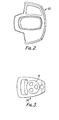
- Fig. 2 is a plan view of a component of the embodiment, and
- Fig. 3 is a plan view of another component.
- The embodiment comprises a cutter head 1 of the so-called clam shell construction with a
lower portion 2 housing an electricdriving motor unit 3 and an upper portion 4 that is upwardly inclined with respect to the lower portion as can be seen from Fig. 1. - The clam shell halves of which only one is shown in Fig. 1 are of a suitable plastics material for example ABS and their mating edges are of a tongue and groove connection to ensure accurate location and to give a degree of rigidity to the assembly.
- The interior surfaces of the clam shell halves are formed with ribs (not shown) which together locate and support a
base plate 5 that forms part of themotor unit 3. The motor unit is placed in position in one clam shell half being located by the ribs therein and then, after the other half shell has been positioned on the first half, is secured in place by screws that pass through the walls of the shell halves and engageslots 6 in the lower face of thebase plate 5. - The upper interior surfaces of the upper portions 4 of the clam shell halves are formed with internally extending screw bosses which locate in diametral holes 7 in a
metal shaft 8 that extends into the portion 4 as shown in Fig. 1 and forms a supporting shaft for the cutter head 1. The lower end of theshaft 8 extends into the portion 4 and is secured in place after assembly of the clam shell halves by screws passed through the bosses and the shaft which is thus held both axially and longitudinally. - The upper end of the
shaft 8 extends into ahandle 10 also of clam shell construction. The upper end of theshaft 8 is secured to the handle clam shell halves in the same manner as the lower end. - The
handle 10 accommodates an electrical switch indicated asblock 11 and which controls the supply of electric power to themotor unit 3 via a control lead (not shown) which passes from thehandle 6 down inside theshaft 8 to the cutter head 1. Theswitch 11 is operated by a user controlledswitching lever 12 pivotally attached to thehandle 10. Power to the tool is supplied via a drop-lead part of which is shown at 13. The clam shell halves of the handle are also made of a suitable plastics material, for example ABS. - Mounted on the
shaft 8 adjacent thehandle 10 is asecond handle 14 that accommodates a reel R containing a supply of flexible filament and a mechanism for regulating the feed of filament from the reel. Details of the mechanism are given below. Thesecond handle 14 enables the user to support and guide the tool more easily. Filament of a suitable plastics material is fed from the reel through aneyelet 14a (shown in dotted lines) on thehandle 14 down alongside theshaft 8 to aguide tube 15 inside the cutter head 1. The tube terminates adjacent thebase plate 5 as can be seen from Fig. 1. - The
lower portion 16 of theguide tube 15 is aligned with the bore of aspindle 17 rotatably mounted in thebase plate 5 by means of bearings shown at 18. Thespindle 17 extends downwardly beyond thebase plate 5 and carries, at its lower end, a driving head 9. The head 9 s of generally cylinder form comprising an upper half 19 and a lower half 20 secured together by three screws one of which is shown at 21. The head 9 is also of a plastics material and it accommodates aguide tube 22 one end of which fits over a nipple formed at the lower end ofspindle 17. The other end ofguide tube 22 is joined to a funnel-like termination 23 secured in the side wall of the head 9. As can be seen from Fig. 1, thetube 22 is of gently curved arcuate form changing direction from a position axially aligned with the bore in thespindle 17 to a position that extends radially outwardly, the mouth of thetermination 23 being laterally spaced from the axis of rotation of thespindle 17 and the head 9. - Filament from the
guide tube 15 passes through the bore in thespindle 17 and throughguide tube 22 exiting from the termination as indicated at 24. That length of filament external of the head 9 is the cutting length as will be described below. Thetube 22 thus guides the filament to follow a change in direction from the axially aligned orientation to the radial orientation. - For reasons that will be become evident below, the
tube 22 is of a material with a lower coefficient of friction, for example PTFE. Alternatively, the interior of the tube may be lined or faced with such a material. It is not essential to employ a tubular guide, other forms are possible but they must provide the guiding and the changes in direction referred to above. - Also mounted upon the
spindle 17 is apulley 25 drivingly coupled by adrive belt 26 to drivepulley 27 on theoutput shaft 28 of thedrive unit 3. Theoutput shaft 28 is actually the armature shaft of the electric motor and is supported for rotation in thebase plate 5 by means of bearings. Also mounted upon theshaft 28 just above thebase plate 5 is afan 29 that, on rotation of the shaft draws air through the motor to cool the latter. Air may be drawn into the head 1 via air inlets (not shown) in the latter, the air exiting from the head via apertures in the clam shell halves adjacent thefan 29. - As has been stated above, the
second handle 14 accommodates a reel on which is wound a supply of filament. The reel is freely rotatable in thehandle 14 but is normally located against rotation by a lock that is released by a user when required to allow filament to be fed from the reel to the head 9. The lock incorporates a mechanism that allows only a predetermined length of filament to be fed from the reel when the lock is released by a user. - More detail of the construciton and operation of the
handle 14 and the lock are found in European Patent Application No. 0 046 050 (81.303566.4) the contents of which are hereby incorporated into the present disclosure by reference. - To use the cutter, the user first ensures that a length of filament has been fed from the reel to the
tube 22 and emerges therefrom as indicated at 24. The motor 1 is then energised by actuating theswitch 11 in thehandle 10 by means oflever 12. This causes the motor to rotate the head 9 and thecutting length 24 is rotated rapidly in a horizontal plane about the axis of rotation of thespindle 17. The filament between the head 9 and the reel is held taut by the action of centrifugal force on theportion 24 so that, when the lock is released by the user, filament is drawn off the reel thereby increasing the length of theportion 24. In that way, the length of theportion 24 can be maintained constant despite breakages and wear that occur during use. Thus, the filament may be fed from the reel whilst the cutter is in use. Alternatively, the user can, of course, stop the motor, release the lock and manually withdraw filament from the reel by grasping the exposedportion 24 and pulling. - The maximum length of the
portion 24 is normally controlled by a cutting blade located within afilament guard 30 fixed to the head 1. Theguard 30 provides a degree of protection for the user as it forms a shield that extends over a part only of the rotational path of theportion 24, the latter being left exposed over the remainder of its path to enable it to effect cutting of vegetation. - The
guard 30 is detachably secured to the lower part of the cutterhead unit 1 in any suitable manner. For example, the front of the lower end of the unit 1 may be formed with a surface with which a corresponding surface on the guard can be interlocked after which the guard is secured in position by a screw located at the rear of the unit and the guard. - It will be appreciated that, as the head 9 rotates it imparts a twist to the filament which causes the latter to become somewhat less flexible and it is found that the filament tends to rub against the interior surface of the
guide tube 22. The use of an antifriction facing on theguide tube 22 or the formation of the latter from material with a low coefficient of friction tends to reduce or minimise the generation of heat by such rubbing. Excessive heating of the filament is undesirable because it impairs the physical strength of the filament and may cause the latter to melt. - The construction of head 9 described above is simpler and cheaper to manufacture than the prior art construction in which filament is fed along the hollow armature shaft. In addition, the construction enables the head 9 to be rotated at a speed different from that of the driving motor.
- It will be appreciated that the cutter head may be driven from the motor via a drive transmission other than a belt drive, for example a gear train could be used or a friction drive.
- In addition, it is possible to incorporate a joint between the unit 1 and the
shaft 8 or to construct the unit 1 in two parts jointed together to enable the inclination of the shaft relatively to the unit 1 to be varied. Adjustment of that inclination enables a user more easily to trim vegetation etc. beneath bushes and lower branches of trees.
Claims (10)
Applications Claiming Priority (2)
| Application Number | Priority Date | Filing Date | Title |
|---|---|---|---|
| GB8330228 | 1983-11-11 | ||
| GB838330228A GB8330228D0 (en) | 1983-11-11 | 1983-11-11 | Vegetation cutters |
Publications (2)
| Publication Number | Publication Date |
|---|---|
| EP0145284A1 true EP0145284A1 (en) | 1985-06-19 |
| EP0145284B1 EP0145284B1 (en) | 1989-04-12 |
Family
ID=10551665
Family Applications (1)
| Application Number | Title | Priority Date | Filing Date |
|---|---|---|---|
| EP84307752A Expired EP0145284B1 (en) | 1983-11-11 | 1984-11-09 | Improvements in or relating to vegetation cutters |
Country Status (5)
| Country | Link |
|---|---|
| US (1) | US4578863A (en) |
| EP (1) | EP0145284B1 (en) |
| CA (1) | CA1230743A (en) |
| DE (1) | DE3477635D1 (en) |
| GB (1) | GB8330228D0 (en) |
Cited By (4)
| Publication number | Priority date | Publication date | Assignee | Title |
|---|---|---|---|---|
| GB2187926A (en) * | 1986-03-18 | 1987-09-23 | Wing Chee Seck | Vegetation cutters |
| FR2661066A1 (en) * | 1990-04-18 | 1991-10-25 | Balva Brigitte | Lawnmower device with an electric motor powered by a battery |
| EP0841000A1 (en) * | 1996-11-08 | 1998-05-13 | Black & Decker Inc. | Battery powered vegetation trimmer |
| EP2044829A1 (en) | 2007-10-05 | 2009-04-08 | Black & Decker, Inc. | Vegetation trimmer having a blowing function |
Families Citing this family (29)
| Publication number | Priority date | Publication date | Assignee | Title |
|---|---|---|---|---|
| US4825548A (en) * | 1987-03-31 | 1989-05-02 | White Consolidated Industries, Inc. | Vibration-damping control handle for a portable power tool |
| GB8714817D0 (en) * | 1987-06-24 | 1987-07-29 | Flymo Ltd | Grass trimmer |
| US5446964A (en) * | 1993-07-22 | 1995-09-05 | Wci Outdoor Products, Inc. | Apparatus and method for packaging and assembling a flexible line trimmer |
| US5594990A (en) * | 1993-07-22 | 1997-01-21 | Wci Outdoor Products, Inc. | Lawn trimming and edging apparatus having motor housing rotatable on extendable handle |
| US5644844A (en) * | 1993-08-02 | 1997-07-08 | The Toro Company | Filament trimmer |
| USD374381S (en) | 1995-06-14 | 1996-10-08 | Black & Decker Inc. | Auxiliary handle for vegetation-cutting tool |
| USD382450S (en) * | 1995-06-14 | 1997-08-19 | Black & Decker Inc. | Vegetation cutter |
| USD380129S (en) * | 1995-06-14 | 1997-06-24 | Black & Decker Inc. | Vegetation-cutting tool |
| USD380359S (en) * | 1996-04-23 | 1997-07-01 | Black & Decker Inc. | Handle for vegetation cutter |
| USD382780S (en) * | 1996-05-06 | 1997-08-26 | Black & Decker Inc. | Guard for vegetation-cutting tool |
| USD394991S (en) | 1996-05-06 | 1998-06-09 | Black & Decker Inc. | Auxiliary handle for vegetation-cutting device |
| USD382778S (en) * | 1996-05-06 | 1997-08-26 | Black & Decker Inc. | Handle for vegetation-cutting tool |
| USD382779S (en) * | 1996-05-06 | 1997-08-26 | Black & Decker Inc. | Guard for vegetation cutter |
| USD398817S (en) | 1997-03-21 | 1998-09-29 | Black & Decker Inc. | Vegetation cutter |
| AU742951B2 (en) | 1998-02-20 | 2002-01-17 | Black & Decker Incorporated | Combination string and blade trimmer with auxiliary blower function |
| USD450226S1 (en) | 2000-02-03 | 2001-11-13 | The Toro Company | Vegetation trimmer |
| SE522871C2 (en) * | 2001-11-28 | 2004-03-16 | Electrolux Abp | Electric work machine |
| US7141946B2 (en) * | 2003-09-15 | 2006-11-28 | Rockwell Automation Technologies, Inc. | Method and apparatus for providing optimal acceleration feedback |
| USD566491S1 (en) | 2006-12-26 | 2008-04-15 | The Toro Company | Vegetation trimmer |
| US20090217637A1 (en) * | 2008-02-28 | 2009-09-03 | Dunn Harold E | Method and apparatus for swinging line |
| WO2009135169A1 (en) * | 2008-05-02 | 2009-11-05 | Edward Carl Holter | Lawn trimmer apparatus |
| JP2013034403A (en) * | 2011-08-04 | 2013-02-21 | Makita Corp | Bush cutter |
| US20140215835A1 (en) * | 2011-08-26 | 2014-08-07 | Husqvarna Ab | Battery powered hand held cutting tool |
| CN103703918A (en) * | 2012-09-28 | 2014-04-09 | 苏州宝时得电动工具有限公司 | Mower |
| US9472992B2 (en) * | 2013-07-11 | 2016-10-18 | The Toro Company | Electric motor support structure and power equipment unit incorporating same |
| US10314228B2 (en) | 2014-05-16 | 2019-06-11 | Positec Power Tools (Suzhou) Co., Ltd. | Grass trimmer and cord delivering method of grass trimmer |
| WO2017059917A1 (en) | 2015-10-08 | 2017-04-13 | Husqvarna Ab | Automatic line feed for trimmer |
| DE102016106557A1 (en) | 2016-04-11 | 2017-10-12 | Festool Gmbh | Hand machine tool with a drive motor |
| US11369057B2 (en) | 2019-11-04 | 2022-06-28 | Black & Decker, Inc. | String trimmer with pole break |
Citations (5)
| Publication number | Priority date | Publication date | Assignee | Title |
|---|---|---|---|---|
| DE2828425A1 (en) * | 1978-06-28 | 1980-01-10 | Stihl Maschf Andreas | PLANT CUTTER |
| DE2930469A1 (en) * | 1978-07-28 | 1980-02-07 | Textron Inc | LAWN CUTTER WITH WHOLE THREAD, WITH A ROTATING CASE |
| US4285128A (en) * | 1979-11-16 | 1981-08-25 | Benchmark Tool Company | Spool feed mechanism for line fed grass trimmer |
| EP0046050A1 (en) * | 1980-08-08 | 1982-02-17 | Black & Decker Inc. | Feed mechanism for filament type vegetation trimmer |
| EP0046051A1 (en) * | 1980-08-08 | 1982-02-17 | Black & Decker Inc. | Filament type vegetation trimmer |
Family Cites Families (5)
| Publication number | Priority date | Publication date | Assignee | Title |
|---|---|---|---|---|
| US3018602A (en) * | 1959-01-26 | 1962-01-30 | Diesterweg Roland Earl | Lawn edger |
| FR2044107A5 (en) * | 1969-05-14 | 1971-02-19 | Reber Walter | |
| US3928911A (en) * | 1974-10-15 | 1975-12-30 | Jr Charles B Pittinger | Hollow-shaft feed filament trimmer |
| US4367587A (en) * | 1978-11-07 | 1983-01-11 | Kilmer Lauren G | Filament vegetation trimmer |
| US4452033A (en) * | 1982-05-20 | 1984-06-05 | Pascal Scramuzza | Lawn mowing and trimming apparatus |
-
1983
- 1983-11-11 GB GB838330228A patent/GB8330228D0/en active Pending
-
1984
- 1984-11-09 US US06/670,379 patent/US4578863A/en not_active Expired - Lifetime
- 1984-11-09 DE DE8484307752T patent/DE3477635D1/en not_active Expired
- 1984-11-09 CA CA000467557A patent/CA1230743A/en not_active Expired
- 1984-11-09 EP EP84307752A patent/EP0145284B1/en not_active Expired
Patent Citations (5)
| Publication number | Priority date | Publication date | Assignee | Title |
|---|---|---|---|---|
| DE2828425A1 (en) * | 1978-06-28 | 1980-01-10 | Stihl Maschf Andreas | PLANT CUTTER |
| DE2930469A1 (en) * | 1978-07-28 | 1980-02-07 | Textron Inc | LAWN CUTTER WITH WHOLE THREAD, WITH A ROTATING CASE |
| US4285128A (en) * | 1979-11-16 | 1981-08-25 | Benchmark Tool Company | Spool feed mechanism for line fed grass trimmer |
| EP0046050A1 (en) * | 1980-08-08 | 1982-02-17 | Black & Decker Inc. | Feed mechanism for filament type vegetation trimmer |
| EP0046051A1 (en) * | 1980-08-08 | 1982-02-17 | Black & Decker Inc. | Filament type vegetation trimmer |
Cited By (6)
| Publication number | Priority date | Publication date | Assignee | Title |
|---|---|---|---|---|
| GB2187926A (en) * | 1986-03-18 | 1987-09-23 | Wing Chee Seck | Vegetation cutters |
| FR2661066A1 (en) * | 1990-04-18 | 1991-10-25 | Balva Brigitte | Lawnmower device with an electric motor powered by a battery |
| EP0841000A1 (en) * | 1996-11-08 | 1998-05-13 | Black & Decker Inc. | Battery powered vegetation trimmer |
| US6014812A (en) * | 1996-11-08 | 2000-01-18 | Black & Decker, Inc. | Battery powered vegetation trimmer |
| US6301788B1 (en) * | 1996-11-08 | 2001-10-16 | Black & Decker Inc. | Battery powered vegetation trimmer |
| EP2044829A1 (en) | 2007-10-05 | 2009-04-08 | Black & Decker, Inc. | Vegetation trimmer having a blowing function |
Also Published As
| Publication number | Publication date |
|---|---|
| GB8330228D0 (en) | 1983-12-21 |
| US4578863A (en) | 1986-04-01 |
| EP0145284B1 (en) | 1989-04-12 |
| CA1230743A (en) | 1987-12-29 |
| DE3477635D1 (en) | 1989-05-18 |
Similar Documents
| Publication | Publication Date | Title |
|---|---|---|
| EP0145284B1 (en) | Improvements in or relating to vegetation cutters | |
| US4338719A (en) | Filament type vegetation trimmer | |
| US4483069A (en) | Apparatus for cutting vegetation | |
| US4346550A (en) | Tape wrapping apparatus | |
| US9379596B2 (en) | Work apparatus | |
| CA1156054A (en) | Feed mechanism for filament type vegetation trimmer | |
| EP0657255A1 (en) | Improved electrically operated tool | |
| SE503050C2 (en) | Cutting device for cutting fibrous reinforcing material | |
| RU96103362A (en) | DEVICE INTENDED FOR THE SUBMISSION OF REINFORCING FIBERS IN THE PRODUCTION OF THERMAL CURING PLASTIC PRODUCTS | |
| US6431409B1 (en) | Extruder welding device | |
| CA2668015A1 (en) | Optical fiber flail with integrated power supply and light source for rotary cutting tools | |
| US2846004A (en) | Fiber cutter | |
| CA1043083A (en) | Cable stripping tool | |
| DE3460303D1 (en) | Device for cooling the electric drive motor for the disc blade of a slicing machine | |
| EP0560542A1 (en) | Motor brake unit for rotary drain and sewer router | |
| US4275675A (en) | Bobbin case with thread guide for cyclic sewing machine | |
| US20230024916A1 (en) | Electric work machine | |
| US1871700A (en) | Shearing machine | |
| US3541984A (en) | Thread-chain cutting device for sewing machines | |
| JP4852335B2 (en) | Grooving tools | |
| US2761450A (en) | Machine for cutting poultry wings | |
| JP2817007B2 (en) | Triangular ear processing device | |
| WO2001098042A2 (en) | Rotary cutter | |
| US1190307A (en) | Thread-cutting machine. | |
| JP4697906B2 (en) | Wallpaper gluing machine and cartridge with built-in rotary blade |
Legal Events
| Date | Code | Title | Description |
|---|---|---|---|
| PUAI | Public reference made under article 153(3) epc to a published international application that has entered the european phase |
Free format text: ORIGINAL CODE: 0009012 |
|
| AK | Designated contracting states |
Designated state(s): BE DE FR GB SE |
|
| 17P | Request for examination filed |
Effective date: 19851011 |
|
| 17Q | First examination report despatched |
Effective date: 19861021 |
|
| GRAA | (expected) grant |
Free format text: ORIGINAL CODE: 0009210 |
|
| AK | Designated contracting states |
Kind code of ref document: B1 Designated state(s): BE DE FR GB SE |
|
| PG25 | Lapsed in a contracting state [announced via postgrant information from national office to epo] |
Ref country code: BE Effective date: 19890412 |
|
| REF | Corresponds to: |
Ref document number: 3477635 Country of ref document: DE Date of ref document: 19890518 |
|
| ET | Fr: translation filed | ||
| PGFP | Annual fee paid to national office [announced via postgrant information from national office to epo] |
Ref country code: SE Payment date: 19891025 Year of fee payment: 6 |
|
| PLBE | No opposition filed within time limit |
Free format text: ORIGINAL CODE: 0009261 |
|
| STAA | Information on the status of an ep patent application or granted ep patent |
Free format text: STATUS: NO OPPOSITION FILED WITHIN TIME LIMIT |
|
| 26N | No opposition filed | ||
| PG25 | Lapsed in a contracting state [announced via postgrant information from national office to epo] |
Ref country code: SE Effective date: 19901110 |
|
| EUG | Se: european patent has lapsed |
Ref document number: 84307752.0 Effective date: 19910705 |
|
| PGFP | Annual fee paid to national office [announced via postgrant information from national office to epo] |
Ref country code: DE Payment date: 19971029 Year of fee payment: 14 |
|
| PGFP | Annual fee paid to national office [announced via postgrant information from national office to epo] |
Ref country code: FR Payment date: 19981020 Year of fee payment: 15 |
|
| PGFP | Annual fee paid to national office [announced via postgrant information from national office to epo] |
Ref country code: GB Payment date: 19981022 Year of fee payment: 15 |
|
| PG25 | Lapsed in a contracting state [announced via postgrant information from national office to epo] |
Ref country code: DE Free format text: LAPSE BECAUSE OF NON-PAYMENT OF DUE FEES Effective date: 19990901 |
|
| PG25 | Lapsed in a contracting state [announced via postgrant information from national office to epo] |
Ref country code: GB Free format text: LAPSE BECAUSE OF NON-PAYMENT OF DUE FEES Effective date: 19991109 |
|
| GBPC | Gb: european patent ceased through non-payment of renewal fee |
Effective date: 19991109 |
|
| PG25 | Lapsed in a contracting state [announced via postgrant information from national office to epo] |
Ref country code: FR Free format text: LAPSE BECAUSE OF NON-PAYMENT OF DUE FEES Effective date: 20000731 |
|
| REG | Reference to a national code |
Ref country code: FR Ref legal event code: ST |