EP0145069B1 - Sonobuoy multiple depth deployment apparatus - Google Patents
Sonobuoy multiple depth deployment apparatus Download PDFInfo
- Publication number
- EP0145069B1 EP0145069B1 EP84201716A EP84201716A EP0145069B1 EP 0145069 B1 EP0145069 B1 EP 0145069B1 EP 84201716 A EP84201716 A EP 84201716A EP 84201716 A EP84201716 A EP 84201716A EP 0145069 B1 EP0145069 B1 EP 0145069B1
- Authority
- EP
- European Patent Office
- Prior art keywords
- rotor
- lip
- cable
- container
- rotative
- Prior art date
- Legal status (The legal status is an assumption and is not a legal conclusion. Google has not performed a legal analysis and makes no representation as to the accuracy of the status listed.)
- Expired
Links
Images



Classifications
-
- G—PHYSICS
- G01—MEASURING; TESTING
- G01S—RADIO DIRECTION-FINDING; RADIO NAVIGATION; DETERMINING DISTANCE OR VELOCITY BY USE OF RADIO WAVES; LOCATING OR PRESENCE-DETECTING BY USE OF THE REFLECTION OR RERADIATION OF RADIO WAVES; ANALOGOUS ARRANGEMENTS USING OTHER WAVES
- G01S15/00—Systems using the reflection or reradiation of acoustic waves, e.g. sonar systems
- G01S15/02—Systems using the reflection or reradiation of acoustic waves, e.g. sonar systems using reflection of acoustic waves
-
- B—PERFORMING OPERATIONS; TRANSPORTING
- B63—SHIPS OR OTHER WATERBORNE VESSELS; RELATED EQUIPMENT
- B63B—SHIPS OR OTHER WATERBORNE VESSELS; EQUIPMENT FOR SHIPPING
- B63B22/00—Buoys
- B63B22/003—Buoys adapted for being launched from an aircraft or water vehicle;, e.g. with brakes deployed in the water
-
- B—PERFORMING OPERATIONS; TRANSPORTING
- B63—SHIPS OR OTHER WATERBORNE VESSELS; RELATED EQUIPMENT
- B63B—SHIPS OR OTHER WATERBORNE VESSELS; EQUIPMENT FOR SHIPPING
- B63B22/00—Buoys
- B63B22/04—Fixations or other anchoring arrangements
- B63B22/08—Fixations or other anchoring arrangements having means to release or urge to the surface a buoy on submergence thereof, e.g. to mark location of a sunken object
-
- G—PHYSICS
- G01—MEASURING; TESTING
- G01F—MEASURING VOLUME, VOLUME FLOW, MASS FLOW OR LIQUID LEVEL; METERING BY VOLUME
- G01F23/00—Indicating or measuring liquid level or level of fluent solid material, e.g. indicating in terms of volume or indicating by means of an alarm
- G01F23/22—Indicating or measuring liquid level or level of fluent solid material, e.g. indicating in terms of volume or indicating by means of an alarm by measuring physical variables, other than linear dimensions, pressure or weight, dependent on the level to be measured, e.g. by difference of heat transfer of steam or water
- G01F23/28—Indicating or measuring liquid level or level of fluent solid material, e.g. indicating in terms of volume or indicating by means of an alarm by measuring physical variables, other than linear dimensions, pressure or weight, dependent on the level to be measured, e.g. by difference of heat transfer of steam or water by measuring the variations of parameters of electromagnetic or acoustic waves applied directly to the liquid or fluent solid material
Definitions
- This invention relates to sonobuoy deployment apparatus and more particularly to preselected depth deployment of the sonobuoy hydrophone.
- Sonobuoys are devices adapted to be dropped by parachute from an aircraft, are equipped with an hydrophone for detecting underwater sound in either an active or passive manner and transducing the sounds to electrical signals and have an automatic radio transmitter for transmitting the signals to air and surface craft.
- a wound cable packed in the sonobuoy connects the surface transmitter and the underwater hydrophone and is automatically payed out after the sonobuoy enters the water.
- the cable length determines the underwater depth of the hydrophone. Different cable lengths are desired for different water bottom depths and other conditions.
- One manner of obtaining different depths is simply to package a wound cable having a length desired for a particular application. Each sonobuoy thus is restricted to only one hydrophone depth.
- a sonobuoy capable of multiple hydrophone deployment depths substantially increases the sonobuoy versatility and reduces sonobuoy logistic requirements and this invention is directed towards this purpose.
- Sonobuoys comprising variable depth deployment means according to the first part of claim 1 are described in US-A-3,262,090 and US-A-3,991,475. The means used in these known sonobuoys are of a rather complicated nature.
- An object of the invention is to provide a sonobuoy with variable depth deployment means of a more simple construction.
- the deployment apparatus of the present invention is defined by the features of claim 1.
- a sonobuoy float canister is releasably latched to a cylindrical wound cable pack container.
- the cable is attached at one end to the float and at the other end to a lower sonobuoy component.
- the cable is provided with a looped end lanyard attached to the cable at a predetermined point intermediate of the cable length corresponding to a predetermined intermediate depth of the underwater component.
- the looped end of the lanyard extends above the wound cable and is releasably captured as later explained.
- a bidirectionally rotatable cam or wedge- shaped rotor is mounted to the bottom end of the float canister and pivotally carries at its narrow end a rod end.
- the rod extends across the canister bottom and its other end is movable into and out of latched contact with the underside of a first lip inwardly extending from the inner surface of the cable pack container.
- the wide end of the rotor is movable into and out of latched contact with the underside of a second lip inwardly extending from the inner surface of the cable pack container at a point diametrically opposite the first lip.
- the rod end and rotor wide end are latched and unlatched substantially simultaneously.
- a "P" shaped wire has its shank rotatably mounted at two spaced points on a vertical axis in a bracket depending from the second lip on the inside surface of the container and is spring urged upwardly.
- the wide end of the rotor is notched to receive the head of the P wire and swings the head about the vertical axis as the rotor turns.
- the second lip has a notch at one side thereof for receiving the head of the P wire and the rotor can swing the head into the lip notch.
- the shank of the P wire is inserted through the looped end of the lanyard and thus the looped end is captured as long as the wire is in the bracket, between the mounting points.
- the rod end is latched to the first lip
- the rotor is latched to the second lip and the looped end of the lanyard is captured by the shank of the P wire.
- the canister is thus latched to the container and no payout of the cable is possible and this corresponds to a first or shallow deployment depth of the lower component.
- the rotor is rotated away from the lip notch so that the looped end of the lanyard remains captured and the rod end and rotor wide end are unlatched from their respective lips, thus releasing or unlatching the canister from the container.
- the cable pays out to the point where the lanyard is attached but no further since the looped end of the lanyard is still captured. This corresponds to the medium or intermediate deployment depth.
- a third rotative position of the rotor the rotor is rotated towards the lip notch and the head of the P wire is swung into alignment with the lip notch at which point the head of the P wire is spring urged into the notch and against the bottom end of the canister releasing the looped end of the lanyard and continued rotation of the rotor to the third position will also unlatch the canister from the container.
- the cable is fully payed out..since the restraint has been removed and the underwater component is deployed to the full length of the
- a bidirectional motor is used to selectively obtain the rotational positions of the rotor.
- the rotor is actuated through a control circuit which initiates the actuation sequence when a salt water battery is flooded with a sea water electrolyte.
- the motor is unactuated.
- the motor is actuated in one rotational direction and to obtain the third rotative position the motor is actuated in the opposite rotational direction.
- Another object of this invention is to provide apparatus of the previous object wherein one deployment depth corresponds to no payout of the deployment cable between the upper and the lower sonobuoy components, a second depth corresponds to partial payout of the cable and a third depth corresponds to full payout of the cable.
- Another object of this invention is to provide in the apparatus of the previous object latching together of the upper and lower sonobuoy components thus preventing cable payout and are unlatched in a first manner to provide partial cable payout and unlatched in a second manner for full cable payout.
- a further object of this invention is to provide in the apparatus of the previous object a looped end lanyard attached to an intermediate point in the cable with the looped end captured in the first manner of unlatching and freed in the second manner of unlatching.
- a sonobuoy 20 prior to deployment has cylindrically tubular outer casing 22, wind blade 24 at the outside upper end thereof and inside thereof in descending order parachute 26, parachute release mechanism shown generally at 28, cylindrical rigid float canister 30, sea water battery 32, upper compliance cable and hard cable pack container 34, electrically conductive lower compliance cable 36, sea anchor 38, lower electronic components and hydrophone container 40 and removable lower end 42.
- Sonobuoy 20 is dropped from aircraft 44 and blade 24 is wind actuated in conventional manner to deploy parachute 26, having a plurality of shroud lines 46 which are releasably attached inside casing 22, to provide a controlled descent to the surface of water 48.
- Canister 30 is connected to upper end of electrically conductive upper compliance cable 56 the lower end of which is connected to the upper end of electronically conductive hard cable 58 the lower end of which is connected to the upper end of lower compliance cable 36.
- Cables 56, 36 are relatively short and resilient to reduce vibration and shock while cable 58 is longer and is dimensioned to provide the desired fully deployed or deep depth of hydrophone 54.
- hydrophone 54 is deployed to the shallow or first depth, canister 30 being latched to container 34; in Fig. 5 hydrophone 54 is deployed to a medium or second depth, canister 30 being unlatched from container 34 and cable 58 being partially payed out; and in Fig. 6 hydrophone 54 is deployed to a deep or third depth with canister 30 being unlatched from container 34 and cable 58 being fully payed out.
- Bottom end 60 of canister 30 is provided with holes 62,64 for receiving rivets 66, 68 respectively which are inserted through holes 70,72 respectively in horizontal leg 74 of L-shaped rod guide bracket 76.
- Bracket 76 has depending arm 78 with guide hole 80 for slidingly receiving end 82 of latching rod 84 for guiding movement of rod end 82 beneath lip 152a and maintaining latching pressure between lip 152a and rod end 82.
- Motor 86 is attached to openings in posts 90, 92 upstanding from the upper surface of bottom 60 with bolts 94,96. Motor 86 is capable of selectively rotating in either the clockwise or counterclockwise rotative direction through an arc of approximately 135°. Other bidirectional motors of similar function may be used.
- Motor 86 has depending shaft key 98 which is inserted in upper keyway 100 of cylindrical coupler 102 which has lower keyway 104. Coupler 102 is rotatably mounted in opening 106 in bottom 60.
- Wedge shaped rotor 108 has a pointed or narrow end 110 in which is formed opening 112 for receiving, for free rotation therein, down-turned end 114 of rod 84.
- Wide end 116 of rotor 108 has funnel shaped notch 118 formed therein slightly off center of end 116.
- Cylindrical base 120 is formed on and upstanding from the upper surface of rotor 108 substantially centrally thereof.
- a stop finger 122 extends radially outwardly from base 120 towards end 116 substantially midway between the sides of end 116.
- Cylindrical post 124 is formed on and upstanding from base 120 and key 126 is formed on and upstanding from post 124 and is received in keyway 104.
- motor 86 rotatively drives rotor 108 through coupler 102.
- Stops 128, 130 depend from the lower surface of bottom 60 and are positioned in the swing path of finger 122 as rotor 108 is rotated clockwise and counter clockwise respectively to limit the rotative arc of rotor
- elongated vertical slide bracket 134 has extending from the outer side thereof substantially square slide 136 having vertical ears 138, 140 on opposite sides thereof.
- Slide 136 is insertable into the upper square shaped portion of T-shaped slot 142 in wall 144 of container 34.
- slot edges 148, 150 slide along the inner surfaces of ears 138,140 respectively until horizontal ledge 146 which is vertically spaced above slide 136 clears the upper edge of slot 142 and snaps into the square opening at the top of slot 142 at which point bracket 134 is firmly attached to wall 144.
- An inwardly extending lip 152 is formed in bracket 134 and has vertical locator peg 154 upstanding therefrom which is insertable into a locator opening, not shown, in bottom 60.
- a V-shaped notch 156 is formed at one side of lip 152 adjacent wall 144 and between the first and third rotative positions of rotor 108.
- Vertically spaced below lip 152 in bracket 134 in vertically spaced alignment are pivot holes 160,162,164 in laterally projecting arms 166, 168, 170 respectively.
- P-shaped wire 172 has square shaped looped head 174, is of a stiff material such as rigid metal wire, and shank 176 depends from head 174. Formed on shank 176 are a pair of spring washer retaining tabs 178, 180.
- Shank 176 is slidingly inserted downwardly through hole 160, is slidingly inserted through the center opening of downwardly convex shaped washer 182 the upper surface of which abuts and is restrained from further sliding movement on shank 176 by tabs 178, 180 and slidingly inserted through coil spring 184.
- the end of shank 176 is slidingly inserted through hole 162 compressing spring 184 between washer 182 and arm 168, Fig. 9, and then through loop 186 at the end of lanyard 188 and then into hole 164.
- Head 174 is turned counterclockwise, as viewed from the top, until it abuts shallow positioning shoulder 190 formed on the underside of lip 152 at which point head 174 is positioned for insertion into notch 118, Fig. 15, and maintaining compression of spring 184.
- Bracket 134a Diametrically opposite bracket 134 in wall 144 is a similar bracket 134a inserted in a T-shaped slot 142a in wall 144 similar to T slot 142 in a similar manner. Bracket 134a has lip 152a extending inwardly of container 34 in the manner of lip 152. Slide 36a, ears 138a 140a and ledge 146a of bracket 134a are all similarly shaped and function in similar manner to the corresponding parts of bracket 134 to firmly attached bracket 134a to the inner surface of wall 144. As will become apparent bracket 134a is utilized for the purpose of providing inwardly extending lip 152a for latching canister 30 to container 34. Bracket 134a is shaped similarly to bracket 152 for reasons of economy of manufacture.
- cable 58 is wound in a multiple layer coil 192 and when fully wound, Fig. 11, cable portions extend above and below coil 192.
- Lanyard 188 extends above coil 192 from a point between coil ends.
- Loop 186 is shown diagrammatically around shank 176 of P wire 172. As mentioned, coil 192 remains fully wound for the first depth deployment.
- coil 192 is unwound from the inside to the outside until lanyard 188 becomes taut, being restrained from further payout by the restraining force applied to loop 186 by shank 176.
- This condition of coil 192 corresponds to the second deployment depth.
- Lanyard 188 in this embodiment is a woven tubular fabric having a portion 189 through which cable 58 is inserted and progressively contracts in diameter and tightens on cable 58 as cable 58 is pulled through portion 189 in a payout direction to firmly attach portion 189 to cable 58.
- a weave of this kind is well known and is sometimes referred to as a "Chinese finger".
- coil 192 In the fully payed out condition of coil 192, Fig. 13, coil 192 is fully unwound, the restraining force of shank 176 on loop 176 having been removed, as later explained. This condition of coil 192 corresponds to the third deployment depth.
- canister 30 is latched to container 34
- Figs. 14, 15 is unlatched from container with loop 186 captured by shank 176
- Fig. 16 is latched to container 34 with lanyard loop 186 released by shank 176, Fig. 17, and is unlatched from container 34 after loop 186 has been released from shank 176, Fig. 18.
- Rotor 108 is in a first rotative or center position in Figs. 14, 15 wherein rod end 82 is underneath lip 152a and rotor end 116 is under lip 152 latching canister 30 to container 34. Head 174 is in notch 118 and also is under lip 152. In this condition, no cable 58 payout from coil 192 is possible and hydrophone 54 is at the first deployment depth.
- rotor 108 In the second rotative position of rotor 108, Fig. 16, rotor 108 has been rotated approximately 90° in the counterclockwise direction, viewed from above, from the first rotative position at which point finger 122 abuts stop 130. End 82 is moved clear of lip 152a and end 116 is moved clear of lip 152 by the rotation of rotor 108. Head 174 has been swung clockwise and shank 176 has been rotated clockwise about the vertical axis of shank 176 by the rotation of rotor 108. Head 174 is still under lip 152 so that no upward movement of shank 176 has taken place and loop 186 is still captured by shank 176 between arms 168, 170.
- canister 30 is unlatched from container 34 and cable 58 payout from coil 192 occurs until the point at which lanyard 188 is attached to cable 58 is reached whereat further payout is prevented since loop 186 is still captured by shank 176.
- Lanyard portion 189 may be attached to any point on cable 58 in coil 192 so that the second deployment depth may be varied as desired.
- control circuit 200 is mounted in canister 30 and has interlocking button switches 202, 204 mounted in the wall of canister 30 and manually accessible from outside of canister 30.
- a display 206 is mounted in the wall of canister 30 and viewable from outside thereof and is coupled to circuit 200 and provided with depth selection information for display.
- Battery 32 is coupled to circuit 200 to power and initiate its control function and motor 86 is coupled to circuit 200 to receive rotative control signals.
- circuit 200 When switch 202 is closed circuit 200 is set for the second deployment depth and when switch 204 is closed circuit 200 is set for the third deployment depth. Display 206 displays the depth selected.
- battery 32 When sonobuoy 20 is immersed in salt water, battery 32 is activated and powers circuit 200 and initiates its control function as set by switches 202, 204. If circuit 200 has been set by switch 202, a signal is provided to motor 86 to actuated it in a counterclockwise rotative direction and if circuit 200 was set by switch 204 a signal is provided to motor 86 to actuate it in a clockwise rotative direction. If neither switch 202 nor 204 has been closed to set circuit 200, no actuating signal is provided to motor 86 and it will not rotate in either direction which corresponds to the first deployment depth as explained above.
- the invention is described in a passive type sonobuoy embodiment, its use is not so limited. It can for example be used in active type sonobuoys as well as air launched buoys other than sonobuoys. This invention can also be used with buoys other than sonobuoys. This invention can also be used with buoys having an air descent control means other than the described parachute and can also be used in buoys having other types of surface float means such as for example an inflatable surface float. In addition, this invention may be actuated by any desired type of driving motor.
- DC motor 209 which may be a low rpm motor or geared down to a low rpm has -terminal 210, -terminal 211 and rotatably drives a rotatable shaft 212.
- Motor 209 is mounted similarly to motor 86 so that shaft 212 is connected to and rotatably drives post 124, rotor 108 and limit switch cam 214 which has inwardly formed shoulders 216, 218.
- Electrical contacts 220, 222 are at the ends of contact arms 224, 226, respectively which are connected to terminals 228, 230 respectively.
- Arm 224 is stiff while arm is resilient and is spring loaded so that contact 222 is urged away from contact 220.
- Arm 226 has cam riding neb 232 that rides the outer surface 234 of cam 214 between shoulders 216, 218 to hold contacts 220, 222 closed. When neb 232 reches either of shoulders 216, 218 contacts 220, 222 open to stop motor 209.
- Double pole triple throw switch 236 has ganged switch blades 238, 240 which are pivoted at poles 242, 244 respectively. Blade 238 contacts terminals 246, 248, 250 when blade 240 contacts terminals 252, 254, 256 respectively.
- Sea water activated battery 258 has its + terminal connected to terminal 230 and its negative terminal connected to pole 242. Pole 244 is connected to terminal 228.
- Shaft 212 is shown in its center position corresponding to the Fig. 15 position of rotor 108, blades 238, 240 being preswitched to terminals 248, 254 respectively.
- blades 238, 240 are preswitched to terminals 246, 252, respectively, connecting the negative terminal of battery 258 to negative motor terminal 211 and connecting the positive terminal of battery 258 to positive motor terminal 210 through contacts 220, 222, blade 240 and terminal 252 to impart, after immersion of battery 258, counterclockwise drive to shaft 212 until neb 232 registers with shoulder 218 after approximately 95° of counterclockwise rotation whereat contacts 220, 222 open and motor 209 is stopped.
- blades 238, 240 are preswitched to terminals 250, 256, respectively, connecting the negative terminal of battery 258 to positive motor terminal 210 and connecting the positive terminal of battery 258 to negative motor terminal 211 through contacts 220, 222, blade 240 and terminal 256 to impart, after immersion of battery 258, clockwise drive to shaft 212 until neb 232 registers with shoulder 216 after approximately 95° of clockwise rotation whereat contacts 220, 222 open and motor 209 is stopped.
- motors or devices known in the art for imparting the required bidirectional rotation to rotor 108 may be used, the motor or device chosen depending on the particular sonobuoy requirements.
Landscapes
- Engineering & Computer Science (AREA)
- Physics & Mathematics (AREA)
- Chemical & Material Sciences (AREA)
- Combustion & Propulsion (AREA)
- Mechanical Engineering (AREA)
- Ocean & Marine Engineering (AREA)
- General Physics & Mathematics (AREA)
- Aviation & Aerospace Engineering (AREA)
- Remote Sensing (AREA)
- Radar, Positioning & Navigation (AREA)
- Thermal Sciences (AREA)
- Acoustics & Sound (AREA)
- Computer Networks & Wireless Communication (AREA)
- Fluid Mechanics (AREA)
- Electromagnetism (AREA)
- Measurement Of Velocity Or Position Using Acoustic Or Ultrasonic Waves (AREA)
- Toys (AREA)
- Laying Of Electric Cables Or Lines Outside (AREA)
- Electric Cable Installation (AREA)
Description
- This invention relates to sonobuoy deployment apparatus and more particularly to preselected depth deployment of the sonobuoy hydrophone.
- Sonobuoys are devices adapted to be dropped by parachute from an aircraft, are equipped with an hydrophone for detecting underwater sound in either an active or passive manner and transducing the sounds to electrical signals and have an automatic radio transmitter for transmitting the signals to air and surface craft. A wound cable packed in the sonobuoy connects the surface transmitter and the underwater hydrophone and is automatically payed out after the sonobuoy enters the water. The cable length determines the underwater depth of the hydrophone. Different cable lengths are desired for different water bottom depths and other conditions.
- One manner of obtaining different depths is simply to package a wound cable having a length desired for a particular application. Each sonobuoy thus is restricted to only one hydrophone depth. A sonobuoy capable of multiple hydrophone deployment depths substantially increases the sonobuoy versatility and reduces sonobuoy logistic requirements and this invention is directed towards this purpose. Sonobuoys comprising variable depth deployment means according to the first part of
claim 1 are described in US-A-3,262,090 and US-A-3,991,475. The means used in these known sonobuoys are of a rather complicated nature. An object of the invention is to provide a sonobuoy with variable depth deployment means of a more simple construction. - The deployment apparatus of the present invention is defined by the features of
claim 1. - A sonobuoy float canister is releasably latched to a cylindrical wound cable pack container. The cable is attached at one end to the float and at the other end to a lower sonobuoy component. The cable is provided with a looped end lanyard attached to the cable at a predetermined point intermediate of the cable length corresponding to a predetermined intermediate depth of the underwater component. The looped end of the lanyard extends above the wound cable and is releasably captured as later explained.
- A bidirectionally rotatable cam or wedge- shaped rotor is mounted to the bottom end of the float canister and pivotally carries at its narrow end a rod end. The rod extends across the canister bottom and its other end is movable into and out of latched contact with the underside of a first lip inwardly extending from the inner surface of the cable pack container. The wide end of the rotor is movable into and out of latched contact with the underside of a second lip inwardly extending from the inner surface of the cable pack container at a point diametrically opposite the first lip. The rod end and rotor wide end are latched and unlatched substantially simultaneously.
- A "P" shaped wire has its shank rotatably mounted at two spaced points on a vertical axis in a bracket depending from the second lip on the inside surface of the container and is spring urged upwardly. The wide end of the rotor is notched to receive the head of the P wire and swings the head about the vertical axis as the rotor turns. The second lip has a notch at one side thereof for receiving the head of the P wire and the rotor can swing the head into the lip notch. The shank of the P wire is inserted through the looped end of the lanyard and thus the looped end is captured as long as the wire is in the bracket, between the mounting points.
- In the first, or center, rotative position of the rotor, the rod end is latched to the first lip, the rotor is latched to the second lip and the looped end of the lanyard is captured by the shank of the P wire. The canister is thus latched to the container and no payout of the cable is possible and this corresponds to a first or shallow deployment depth of the lower component. In a second rotative position of the rotor, the rotor is rotated away from the lip notch so that the looped end of the lanyard remains captured and the rod end and rotor wide end are unlatched from their respective lips, thus releasing or unlatching the canister from the container. The cable pays out to the point where the lanyard is attached but no further since the looped end of the lanyard is still captured. This corresponds to the medium or intermediate deployment depth. In a third rotative position of the rotor the rotor is rotated towards the lip notch and the head of the P wire is swung into alignment with the lip notch at which point the head of the P wire is spring urged into the notch and against the bottom end of the canister releasing the looped end of the lanyard and continued rotation of the rotor to the third position will also unlatch the canister from the container. The cable is fully payed out..since the restraint has been removed and the underwater component is deployed to the full length of the
- cable. A bidirectional motor is used to selectively obtain the rotational positions of the rotor. The rotor is actuated through a control circuit which initiates the actuation sequence when a salt water battery is flooded with a sea water electrolyte. To obtain the first rotative position of the rotor the motor is unactuated. To obtain the second rotative position of the rotor the motor is actuated in one rotational direction and to obtain the third rotative position the motor is actuated in the opposite rotational direction.
- It is therefore an object of this invention to provide a sonobuoy deployment apparatus having a plurality of selectable hydrophone deployment depths.
- Another object of this invention is to provide apparatus of the previous object wherein one deployment depth corresponds to no payout of the deployment cable between the upper and the lower sonobuoy components, a second depth corresponds to partial payout of the cable and a third depth corresponds to full payout of the cable.
- It is a further object of this invention to provide apparatus of the previous object utilizing a rotor having a plurality of operating rotative positions, each position corresponding to a different lower component depth.
- Another object of this invention is to provide in the apparatus of the previous object latching together of the upper and lower sonobuoy components thus preventing cable payout and are unlatched in a first manner to provide partial cable payout and unlatched in a second manner for full cable payout.
- A further object of this invention is to provide in the apparatus of the previous object a looped end lanyard attached to an intermediate point in the cable with the looped end captured in the first manner of unlatching and freed in the second manner of unlatching.
- The above mentioned and other features and objects of this invention and the manner of obtaining them will become more apparent and the invention itself will be best understood by reference to the following description of an embodiment of the invention taken in conjunction with the accompanying drawings.
-
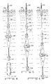
- Fig. 1 is a vertical section, shown diagrammatically, of a sonobuoy utilizing the mechanism of this invention;
- Fig. 2 is a perspective view of a sonobuoy of Fig. 1 with the parachute deployed and about to enter the water after being released from an aircraft;
- Fig. 3 is a view in perspective of the sonobuoy of Fig. 2 after it has entered the water and the parachute has been ejected;
- Fig. 4 is a simplified, partially in perspective and partially broken view of a sonobuoy in a first or shallow depth deployment;
- Fig. 5 is a view similar to Fig. 4 of the sonobuoy in a second or medium depth deployment;
- Fig. 6 is a view similar to Fig. 4 of the sonobuoy in a third or deep depth deployment;
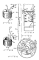
- Fig. 7 is an exploded perspective view of the mechanism of this invention used to obtain the selectable multiple depth deployment;
- Fig. 8 is an enlarged exploded perspective partially broken view of the lanyard retention and release mechanism of this invention;
- Fig. 9 is an enlarged perspective partially broken view of the mechanism of Fig. 8 mounted to the cable pack container inner surface and showing the looped end of the lanyard in a retained or captured condition;
- Fig. 10 is a view similar to Fig. 9 showing the looped end in a released condition;
- Fig. 11 is a perspective view of the fully wound cable pack coil showing the lanyard protruding from the upper end and the P shaped wire inserted through the looped end as it is for the first depth deployment;
- Fig. 12 is a view similar to Fig. 11 with the cable pack coil partially payed out and restrained from further pay out by the lanyard end retention by the P wire as it is for the second depth deployment;
- Fig. 13 is a view similar to Fig. 11 with the lanyard end released and the coil fully payed out as it is for the third depth deployment;
- Fig. 14 is a partial, simplified longitudinal section of the float canister latched to the cable pack container;
- Fig. 15 is an enlarged section taken at 15-15 of Fig. 14 with the release mechanism rotor shown in a first rotative position corresponding to the first deployment depth;
- Fig. 16 is a view similar to Fig. 15 with the release mechanism rotor shown in a second rotative position corresponding to the second deployment depth;
- Fig. 17 is a view similar to Fig. 15 with the release mechanism shown in a rotative position wherein the looped end of the lanyard is released;
- Fig. 18 is a view similar to Fig. 15 with the release mechanism rotor in a third rotative position corresponding to the third deployment depth;
- Fig. 19 is a schematic diagram of the control circuit mounted in the float canister for actuating the rotor motor; and
- Fig. 20 is a schematic diagram of a bidirectional motor system for use in this invention.
- Referring to Figs. 1-6 a
sonobuoy 20 prior to deployment has cylindrically tubularouter casing 22,wind blade 24 at the outside upper end thereof and inside thereof in descendingorder parachute 26, parachute release mechanism shown generally at 28, cylindricalrigid float canister 30,sea water battery 32, upper compliance cable and hardcable pack container 34, electrically conductivelower compliance cable 36,sea anchor 38, lower electronic components andhydrophone container 40 and removablelower end 42.Sonobuoy 20 is dropped fromaircraft 44 andblade 24 is wind actuated in conventional manner to deployparachute 26, having a plurality ofshroud lines 46 which are releasably attached insidecasing 22, to provide a controlled descent to the surface ofwater 48. - After casing 22 enters
water 48parachute 26,lines 46 andparachute cup 50 attached to the lower ends oflines 46 are ejected and the buoyancy force ofcanister 30 causes separation ofcanister 30 fromcasing 22.Antenna 52 is automatically extended fromcanister 30 and extends above the surface ofwater 48 for transmission of signals fromhydrophone 54, which may be active or passive as is known in the art. -
Canister 30 is connected to upper end of electrically conductiveupper compliance cable 56 the lower end of which is connected to the upper end of electronically conductivehard cable 58 the lower end of which is connected to the upper end oflower compliance cable 36.Cables cable 58 is longer and is dimensioned to provide the desired fully deployed or deep depth ofhydrophone 54. - The lower end of
cable 36 is connected to the top ofanchor 38 the lower end of which is connected tohydrophone 54. In the deployed condition shown in Fig. 4, casing 22 is free of its previous contents and sinks to the bottom which is facilitated by release ofend 42. - In Fig. 4
hydrophone 54 is deployed to the shallow or first depth,canister 30 being latched tocontainer 34; in Fig. 5hydrophone 54 is deployed to a medium or second depth,canister 30 being unlatched fromcontainer 34 andcable 58 being partially payed out; and in Fig. 6hydrophone 54 is deployed to a deep or third depth withcanister 30 being unlatched fromcontainer 34 andcable 58 being fully payed out. - Referring to Fig. 7 the unlatching and release mechanism is shown.
Bottom end 60 ofcanister 30 is provided withholes rivets holes horizontal leg 74 of L-shapedrod guide bracket 76.Bracket 76 has dependingarm 78 withguide hole 80 for slidingly receivingend 82 of latchingrod 84 for guiding movement ofrod end 82 beneathlip 152a and maintaining latching pressure betweenlip 152a androd end 82.Motor 86 is attached to openings in posts 90, 92 upstanding from the upper surface of bottom 60 with bolts 94,96.Motor 86 is capable of selectively rotating in either the clockwise or counterclockwise rotative direction through an arc of approximately 135°. Other bidirectional motors of similar function may be used.Motor 86 has depending shaft key 98 which is inserted inupper keyway 100 ofcylindrical coupler 102 which haslower keyway 104.Coupler 102 is rotatably mounted in opening 106 in bottom 60. - Wedge shaped
rotor 108 has a pointed ornarrow end 110 in which is formedopening 112 for receiving, for free rotation therein, down-turnedend 114 ofrod 84.Wide end 116 ofrotor 108 has funnel shapednotch 118 formed therein slightly off center ofend 116.Cylindrical base 120 is formed on and upstanding from the upper surface ofrotor 108 substantially centrally thereof. Astop finger 122 extends radially outwardly frombase 120 towardsend 116 substantially midway between the sides ofend 116.Cylindrical post 124 is formed on and upstanding frombase 120 and key 126 is formed on and upstanding frompost 124 and is received inkeyway 104. Thusly motor 86 rotatively drivesrotor 108 throughcoupler 102.Stops finger 122 asrotor 108 is rotated clockwise and counter clockwise respectively to limit the rotative arc ofrotor 108. - Referring to Figs 7-9 elongated
vertical slide bracket 134 has extending from the outer side thereof substantiallysquare slide 136 havingvertical ears Slide 136 is insertable into the upper square shaped portion of T-shapedslot 142 inwall 144 ofcontainer 34. Asslide 136 is moved downwardly inslot 142, slot edges 148, 150 slide along the inner surfaces of ears 138,140 respectively untilhorizontal ledge 146 which is vertically spaced aboveslide 136 clears the upper edge ofslot 142 and snaps into the square opening at the top ofslot 142 at whichpoint bracket 134 is firmly attached towall 144. - An inwardly extending
lip 152 is formed inbracket 134 and hasvertical locator peg 154 upstanding therefrom which is insertable into a locator opening, not shown, inbottom 60. A V-shapednotch 156 is formed at one side oflip 152adjacent wall 144 and between the first and third rotative positions ofrotor 108. Vertically spaced belowlip 152 inbracket 134 in vertically spaced alignment are pivot holes 160,162,164 in laterally projectingarms wire 172 has square shaped loopedhead 174, is of a stiff material such as rigid metal wire, andshank 176 depends fromhead 174. Formed onshank 176 are a pair of springwasher retaining tabs Shank 176 is slidingly inserted downwardly throughhole 160, is slidingly inserted through the center opening of downwardly convex shapedwasher 182 the upper surface of which abuts and is restrained from further sliding movement onshank 176 bytabs coil spring 184. The end ofshank 176 is slidingly inserted throughhole 162compressing spring 184 betweenwasher 182 andarm 168, Fig. 9, and then throughloop 186 at the end oflanyard 188 and then intohole 164.Head 174 is turned counterclockwise, as viewed from the top, until it abutsshallow positioning shoulder 190 formed on the underside oflip 152 at whichpoint head 174 is positioned for insertion intonotch 118, Fig. 15, and maintaining compression ofspring 184. - Diametrically
opposite bracket 134 inwall 144 is asimilar bracket 134a inserted in a T-shaped slot 142a inwall 144 similar toT slot 142 in a similar manner.Bracket 134a haslip 152a extending inwardly ofcontainer 34 in the manner oflip 152. Slide 36a,ears 138a 140a and ledge 146a ofbracket 134a are all similarly shaped and function in similar manner to the corresponding parts ofbracket 134 to firmly attachedbracket 134a to the inner surface ofwall 144. As will becomeapparent bracket 134a is utilized for the purpose of providing inwardly extendinglip 152a for latchingcanister 30 tocontainer 34.Bracket 134a is shaped similarly tobracket 152 for reasons of economy of manufacture. - Referring to Figs. 11-13
cable 58 is wound in amultiple layer coil 192 and when fully wound, Fig. 11, cable portions extend above and belowcoil 192.Lanyard 188 extends abovecoil 192 from a point between coil ends.Loop 186 is shown diagrammatically aroundshank 176 ofP wire 172. As mentioned,coil 192 remains fully wound for the first depth deployment. - In the partially payed out condition of
coil 192, Fig. 12,coil 192 is unwound from the inside to the outside untillanyard 188 becomes taut, being restrained from further payout by the restraining force applied toloop 186 byshank 176. This condition ofcoil 192 corresponds to the second deployment depth.Lanyard 188 in this embodiment is a woven tubular fabric having aportion 189 through whichcable 58 is inserted and progressively contracts in diameter and tightens oncable 58 ascable 58 is pulled throughportion 189 in a payout direction to firmly attachportion 189 tocable 58. A weave of this kind is well known and is sometimes referred to as a "Chinese finger". - In the fully payed out condition of
coil 192, Fig. 13,coil 192 is fully unwound, the restraining force ofshank 176 onloop 176 having been removed, as later explained. This condition ofcoil 192 corresponds to the third deployment depth. - Referring to Figs. 14-18,
canister 30 is latched tocontainer 34, Figs. 14, 15, is unlatched from container withloop 186 captured byshank 176, Fig. 16 is latched tocontainer 34 withlanyard loop 186 released byshank 176, Fig. 17, and is unlatched fromcontainer 34 afterloop 186 has been released fromshank 176, Fig. 18. -
Rotor 108, is in a first rotative or center position in Figs. 14, 15 whereinrod end 82 is underneathlip 152a androtor end 116 is underlip 152 latchingcanister 30 tocontainer 34.Head 174 is innotch 118 and also is underlip 152. In this condition, nocable 58 payout fromcoil 192 is possible andhydrophone 54 is at the first deployment depth. - In the second rotative position of
rotor 108, Fig. 16,rotor 108 has been rotated approximately 90° in the counterclockwise direction, viewed from above, from the first rotative position at whichpoint finger 122 abuts stop 130.End 82 is moved clear oflip 152a and end 116 is moved clear oflip 152 by the rotation ofrotor 108.Head 174 has been swung clockwise andshank 176 has been rotated clockwise about the vertical axis ofshank 176 by the rotation ofrotor 108.Head 174 is still underlip 152 so that no upward movement ofshank 176 has taken place andloop 186 is still captured byshank 176 betweenarms canister 30 is unlatched fromcontainer 34 andcable 58 payout fromcoil 192 occurs until the point at whichlanyard 188 is attached tocable 58 is reached whereat further payout is prevented sinceloop 186 is still captured byshank 176.Lanyard portion 189 may be attached to any point oncable 58 incoil 192 so that the second deployment depth may be varied as desired. - In the third rotative position, Fig. 18, of
rotor 108motor 86 has rotatedrotor 108 approximately 90° clockwise from the first rotative position untilfinger 122 abuts stop 128.End 82 is moved clear oflip 152a and end 116 is moved clear oflip 152 thereby unlatchingcanister 30 fromcontainer 34. During the rotation ofrotor 108,head 174 is swung counterclockwise andshank 176 has been rotated counterclockwise about the vertical axis ofshank 176 by the rotation ofrotor 108,head 174 sliding underlip 152 until it reachesnotch 156, Fig. 17, at which time it is spring urged upwardly throughnotch 156 against bottom 60, withshank 76 moving upwardly under the force of spring 184 a distance sufficient to clear the vertical distance betweenarm 170 andarm 168 releasingloop end 186, Fig. 10. Full payout ofcoil 192 occurs, Fig. 13, to obtain the third deployment depth. - Referring to Fig. 19
control circuit 200 is mounted incanister 30 and has interlocking button switches 202, 204 mounted in the wall ofcanister 30 and manually accessible from outside ofcanister 30. Adisplay 206 is mounted in the wall ofcanister 30 and viewable from outside thereof and is coupled tocircuit 200 and provided with depth selection information for display.Battery 32 is coupled tocircuit 200 to power and initiate its control function andmotor 86 is coupled tocircuit 200 to receive rotative control signals. - When
switch 202 is closedcircuit 200 is set for the second deployment depth and when switch 204 is closedcircuit 200 is set for the third deployment depth.Display 206 displays the depth selected. When sonobuoy 20 is immersed in salt water,battery 32 is activated andpowers circuit 200 and initiates its control function as set byswitches 202, 204. Ifcircuit 200 has been set byswitch 202, a signal is provided tomotor 86 to actuated it in a counterclockwise rotative direction and ifcircuit 200 was set by switch 204 a signal is provided tomotor 86 to actuate it in a clockwise rotative direction. If neitherswitch 202 nor 204 has been closed to setcircuit 200, no actuating signal is provided tomotor 86 and it will not rotate in either direction which corresponds to the first deployment depth as explained above. - Although the invention is described in a passive type sonobuoy embodiment, its use is not so limited. It can for example be used in active type sonobuoys as well as air launched buoys other than sonobuoys. This invention can also be used with buoys other than sonobuoys. This invention can also be used with buoys having an air descent control means other than the described parachute and can also be used in buoys having other types of surface float means such as for example an inflatable surface float. In addition, this invention may be actuated by any desired type of driving motor.
- Referring to Fig. 20 another system for bidirectional rotation of
post 124 androtor 108 is shown.DC motor 209 which may be a low rpm motor or geared down to a low rpm has -terminal 210, -terminal 211 and rotatably drives arotatable shaft 212.Motor 209 is mounted similarly tomotor 86 so thatshaft 212 is connected to and rotatably drives post 124,rotor 108 andlimit switch cam 214 which has inwardly formedshoulders -
Electrical contacts contact arms 224, 226, respectively which are connected toterminals contact 222 is urged away fromcontact 220.Arm 226 hascam riding neb 232 that rides theouter surface 234 ofcam 214 betweenshoulders contacts neb 232 reches either ofshoulders contacts motor 209. - Double pole
triple throw switch 236 has gangedswitch blades poles Blade 238contacts terminals blade 240contacts terminals battery 258 has its + terminal connected toterminal 230 and its negative terminal connected topole 242.Pole 244 is connected toterminal 228. -
Shaft 212 is shown in its center position corresponding to the Fig. 15 position ofrotor 108,blades terminals rotor 108 be in the position shown in Fig. 18,blades terminals battery 258 tonegative motor terminal 211 and connecting the positive terminal ofbattery 258 topositive motor terminal 210 throughcontacts blade 240 and terminal 252 to impart, after immersion ofbattery 258, counterclockwise drive toshaft 212 untilneb 232 registers withshoulder 218 after approximately 95° of counterclockwise rotation whereatcontacts motor 209 is stopped. When it is desired thatrotor 108 be in the position shown in Fig. 16,blades terminals 250, 256, respectively, connecting the negative terminal ofbattery 258 topositive motor terminal 210 and connecting the positive terminal ofbattery 258 tonegative motor terminal 211 throughcontacts blade 240 and terminal 256 to impart, after immersion ofbattery 258, clockwise drive toshaft 212 untilneb 232 registers withshoulder 216 after approximately 95° of clockwise rotation whereatcontacts motor 209 is stopped. - As mentioned other motors or devices known in the art for imparting the required bidirectional rotation to
rotor 108 may be used, the motor or device chosen depending on the particular sonobuoy requirements. - While there have been described above the principles of this invention in connection with specific embodiments, it is to be understood that this is by way of example and is not limiting of the scope of this invention.
Claims (8)
Applications Claiming Priority (2)
| Application Number | Priority Date | Filing Date | Title |
|---|---|---|---|
| US06/555,979 US4590590A (en) | 1983-11-29 | 1983-11-29 | Sonobuoy multiple depth deployment apparatus |
| US555979 | 1983-11-29 |
Publications (3)
| Publication Number | Publication Date |
|---|---|
| EP0145069A2 EP0145069A2 (en) | 1985-06-19 |
| EP0145069A3 EP0145069A3 (en) | 1985-08-21 |
| EP0145069B1 true EP0145069B1 (en) | 1988-01-20 |
Family
ID=24219403
Family Applications (1)
| Application Number | Title | Priority Date | Filing Date |
|---|---|---|---|
| EP84201716A Expired EP0145069B1 (en) | 1983-11-29 | 1984-11-26 | Sonobuoy multiple depth deployment apparatus |
Country Status (9)
| Country | Link |
|---|---|
| US (1) | US4590590A (en) |
| EP (1) | EP0145069B1 (en) |
| JP (1) | JPS60157059A (en) |
| KR (1) | KR920002372B1 (en) |
| AU (1) | AU573488B2 (en) |
| CA (1) | CA1230405A (en) |
| DE (1) | DE3468847D1 (en) |
| ES (1) | ES8607852A1 (en) |
| IL (1) | IL73663A (en) |
Families Citing this family (17)
| Publication number | Priority date | Publication date | Assignee | Title |
|---|---|---|---|---|
| USRE33014E (en) * | 1986-01-08 | 1989-08-08 | Sparton Of Canada, Ltd. | Cable deployment unit |
| US4727520A (en) * | 1987-01-07 | 1988-02-23 | Sparton Of Canada, Ltd. | Cable deployment unit |
| US4850915A (en) * | 1987-04-10 | 1989-07-25 | Hazeltine Corporation | Apparatus for deploying and supporting a large aperture volumetric array in a medium |
| US5073136A (en) * | 1990-03-29 | 1991-12-17 | Magnavox Government And Industrial Electronics Company | Collapsible sonobuoy floatation device |
| GB2275041A (en) * | 1993-02-05 | 1994-08-17 | Benthos Inc | Cable,hose or rope supply:coiling and uncoiling |
| USD363445S (en) | 1993-10-28 | 1995-10-24 | Gilman Corporation | Ocean buoy |
| GB2339172A (en) * | 1998-07-04 | 2000-01-19 | Thomson Marconi Sonar Limited | Sonobuoy |
| US20060102764A1 (en) * | 2004-11-17 | 2006-05-18 | Naeckel Arno T Jr | Disposable Variable Depth Anchor Cable Pack |
| US20060214050A1 (en) * | 2004-11-17 | 2006-09-28 | Naeckel Arno T | Disposable variable depth anchor cable pack |
| DE102005062108A1 (en) * | 2005-12-23 | 2007-08-30 | Atlas Elektronik Gmbh | Reconnaissance module for deployment in a sea area |
| US7390233B2 (en) * | 2006-03-09 | 2008-06-24 | Lockheed Martin Corporation | Station keeping maneuverable articulating autonomous regenerative tactical (SMAART) buoy |
| JP5076653B2 (en) * | 2007-06-07 | 2012-11-21 | 日本電気株式会社 | COMMUNICATION SYSTEM, COMMUNICATION METHOD, AND BASE STATION DEVICE |
| US9745034B2 (en) | 2015-11-02 | 2017-08-29 | The Boeing Company | Waterborne payload deployment vessel and method |
| CN113075664B (en) * | 2021-03-11 | 2023-12-05 | 长沙金信诺防务技术有限公司 | Expansion sonar volume array |
| CN114379747B (en) * | 2021-12-27 | 2023-05-09 | 上海源威建设工程有限公司 | Stable ground grabber for underwater operation |
| CN114394213A (en) * | 2021-12-31 | 2022-04-26 | 深圳市森讯达电子技术有限公司 | A water rescue robot |
| CN121348295B (en) * | 2025-12-18 | 2026-04-07 | 之江实验室 | Deep-sea imaging sonar and its manufacturing method |
Citations (2)
| Publication number | Priority date | Publication date | Assignee | Title |
|---|---|---|---|---|
| US3262090A (en) * | 1964-03-26 | 1966-07-19 | Sanders Associates Inc | Sonobuoy depth selection mechanism |
| US3991475A (en) * | 1975-12-05 | 1976-11-16 | The United States Of America As Represented By The Secretary Of The Navy | Depth selecting spool device |
Family Cites Families (5)
| Publication number | Priority date | Publication date | Assignee | Title |
|---|---|---|---|---|
| US3786403A (en) * | 1968-05-10 | 1974-01-15 | Us Navy | Underwater acoustical detection system |
| US4029233A (en) * | 1973-03-29 | 1977-06-14 | Sparton Corporation | Sonobuoy retainer plate |
| JPS514450A (en) * | 1974-06-28 | 1976-01-14 | Chuo Hatsujo Kk | Senijotono sozaiyorinarurakuseizainotameno ketsugohojigu |
| US4096598A (en) * | 1977-03-21 | 1978-06-27 | Mason Russell I | Selected depth mooring system |
| US4464130A (en) * | 1981-10-08 | 1984-08-07 | Raytheon Company | Multiple depth selector mechanism |
-
1983
- 1983-11-29 US US06/555,979 patent/US4590590A/en not_active Expired - Fee Related
-
1984
- 1984-11-26 EP EP84201716A patent/EP0145069B1/en not_active Expired
- 1984-11-26 ES ES537963A patent/ES8607852A1/en not_active Expired
- 1984-11-26 DE DE8484201716T patent/DE3468847D1/en not_active Expired
- 1984-11-27 AU AU35899/84A patent/AU573488B2/en not_active Ceased
- 1984-11-28 CA CA000468850A patent/CA1230405A/en not_active Expired
- 1984-11-28 IL IL73663A patent/IL73663A/en not_active IP Right Cessation
- 1984-11-29 JP JP59250646A patent/JPS60157059A/en active Pending
- 1984-11-29 KR KR1019840007509A patent/KR920002372B1/en not_active Expired
Patent Citations (2)
| Publication number | Priority date | Publication date | Assignee | Title |
|---|---|---|---|---|
| US3262090A (en) * | 1964-03-26 | 1966-07-19 | Sanders Associates Inc | Sonobuoy depth selection mechanism |
| US3991475A (en) * | 1975-12-05 | 1976-11-16 | The United States Of America As Represented By The Secretary Of The Navy | Depth selecting spool device |
Also Published As
| Publication number | Publication date |
|---|---|
| EP0145069A2 (en) | 1985-06-19 |
| DE3468847D1 (en) | 1988-02-25 |
| US4590590A (en) | 1986-05-20 |
| KR850004804A (en) | 1985-07-27 |
| JPS60157059A (en) | 1985-08-17 |
| CA1230405A (en) | 1987-12-15 |
| AU573488B2 (en) | 1988-06-09 |
| ES537963A0 (en) | 1986-06-01 |
| KR920002372B1 (en) | 1992-03-23 |
| ES8607852A1 (en) | 1986-06-01 |
| EP0145069A3 (en) | 1985-08-21 |
| IL73663A (en) | 1988-10-31 |
| AU3589984A (en) | 1985-06-06 |
Similar Documents
| Publication | Publication Date | Title |
|---|---|---|
| US4590590A (en) | Sonobuoy multiple depth deployment apparatus | |
| JP6242975B1 (en) | Navigation body recovery device and navigation body recovery method | |
| EP4048584B1 (en) | A system for retrieval of objects lost in water | |
| US20110034094A1 (en) | Submerged buoy | |
| KR101852720B1 (en) | Underwater ultrasonic remote buoy | |
| EP0150526B1 (en) | Sonobuoy retaining and release apparatus | |
| US5111609A (en) | Bait moving fishing bobber | |
| CN210724800U (en) | Unmanned aerial vehicle communication relay device and adopt device's unmanned aerial vehicle | |
| US3646505A (en) | Automatically deployable sonobuoy | |
| US3309649A (en) | Sonobuoy with depth selection capabilities | |
| US4907363A (en) | Weather insulated tip-up light mounting | |
| US3156933A (en) | Marker buoy | |
| JPH0674922U (en) | Double acting pressure release device | |
| US3708812A (en) | Equipment housing for submarine suspension | |
| CN119043284B (en) | Release device of polar region section observation system | |
| EP3417704A1 (en) | An unmanned aerial vehicle used in fishing | |
| US20240367755A1 (en) | Underwater retrieval device and rewinding systems | |
| KR200379254Y1 (en) | A fishing net robbery prevention and the fishing net easily collect for buoyancy means | |
| US4464130A (en) | Multiple depth selector mechanism | |
| CN116062093A (en) | Releaser, releaser control method and ocean observation system | |
| US4657517A (en) | Apparatus for aiding the anchoring of a boat | |
| JPS6224639Y2 (en) | ||
| CA1050150A (en) | Self propelled array system | |
| US12599118B2 (en) | Systems and methods of acoustic release aquatic trap | |
| RU2208539C2 (en) | Device for storage of information recording equipment and removal of it from deep-sea object |
Legal Events
| Date | Code | Title | Description |
|---|---|---|---|
| PUAI | Public reference made under article 153(3) epc to a published international application that has entered the european phase |
Free format text: ORIGINAL CODE: 0009012 |
|
| PUAL | Search report despatched |
Free format text: ORIGINAL CODE: 0009013 |
|
| AK | Designated contracting states |
Designated state(s): BE DE FR GB IT NL SE |
|
| AK | Designated contracting states |
Designated state(s): BE DE FR GB IT NL SE |
|
| 17P | Request for examination filed |
Effective date: 19860219 |
|
| 17Q | First examination report despatched |
Effective date: 19860917 |
|
| GRAA | (expected) grant |
Free format text: ORIGINAL CODE: 0009210 |
|
| AK | Designated contracting states |
Kind code of ref document: B1 Designated state(s): BE DE FR GB IT NL SE |
|
| REF | Corresponds to: |
Ref document number: 3468847 Country of ref document: DE Date of ref document: 19880225 |
|
| ITF | It: translation for a ep patent filed | ||
| ET | Fr: translation filed | ||
| PLBE | No opposition filed within time limit |
Free format text: ORIGINAL CODE: 0009261 |
|
| STAA | Information on the status of an ep patent application or granted ep patent |
Free format text: STATUS: NO OPPOSITION FILED WITHIN TIME LIMIT |
|
| 26N | No opposition filed | ||
| ITTA | It: last paid annual fee | ||
| ITPR | It: changes in ownership of a european patent |
Owner name: CAMBIO RAGIONE SOCIALE;MAGNAVOX ELECTRONIC SYSTEMS |
|
| REG | Reference to a national code |
Ref country code: FR Ref legal event code: CD |
|
| NLT1 | Nl: modifications of names registered in virtue of documents presented to the patent office pursuant to art. 16 a, paragraph 1 |
Owner name: MAGNAVOX ELECTRONIC SYSTEMS COMPANY TE FORT WAYNE, |
|
| PGFP | Annual fee paid to national office [announced via postgrant information from national office to epo] |
Ref country code: GB Payment date: 19941031 Year of fee payment: 11 |
|
| PGFP | Annual fee paid to national office [announced via postgrant information from national office to epo] |
Ref country code: SE Payment date: 19941124 Year of fee payment: 11 |
|
| PGFP | Annual fee paid to national office [announced via postgrant information from national office to epo] |
Ref country code: FR Payment date: 19941125 Year of fee payment: 11 |
|
| PGFP | Annual fee paid to national office [announced via postgrant information from national office to epo] |
Ref country code: NL Payment date: 19941130 Year of fee payment: 11 |
|
| PGFP | Annual fee paid to national office [announced via postgrant information from national office to epo] |
Ref country code: BE Payment date: 19941205 Year of fee payment: 11 |
|
| PGFP | Annual fee paid to national office [announced via postgrant information from national office to epo] |
Ref country code: DE Payment date: 19950124 Year of fee payment: 11 |
|
| EAL | Se: european patent in force in sweden |
Ref document number: 84201716.2 |
|
| PG25 | Lapsed in a contracting state [announced via postgrant information from national office to epo] |
Ref country code: GB Effective date: 19951126 |
|
| PG25 | Lapsed in a contracting state [announced via postgrant information from national office to epo] |
Ref country code: SE Effective date: 19951127 |
|
| PG25 | Lapsed in a contracting state [announced via postgrant information from national office to epo] |
Ref country code: BE Effective date: 19951130 |
|
| BERE | Be: lapsed |
Owner name: MAGNAVOX ELECTRONICS SYSTEMS CY Effective date: 19951130 |
|
| PG25 | Lapsed in a contracting state [announced via postgrant information from national office to epo] |
Ref country code: NL Effective date: 19960601 |
|
| GBPC | Gb: european patent ceased through non-payment of renewal fee |
Effective date: 19951126 |
|
| PG25 | Lapsed in a contracting state [announced via postgrant information from national office to epo] |
Ref country code: FR Effective date: 19960731 |
|
| NLV4 | Nl: lapsed or anulled due to non-payment of the annual fee |
Effective date: 19960601 |
|
| PG25 | Lapsed in a contracting state [announced via postgrant information from national office to epo] |
Ref country code: DE Effective date: 19960801 |
|
| EUG | Se: european patent has lapsed |
Ref document number: 84201716.2 |
|
| REG | Reference to a national code |
Ref country code: FR Ref legal event code: ST |