EP0144662A1 - Apparatus and method for cleaning flowable material filling devices - Google Patents
Apparatus and method for cleaning flowable material filling devices Download PDFInfo
- Publication number
- EP0144662A1 EP0144662A1 EP84112659A EP84112659A EP0144662A1 EP 0144662 A1 EP0144662 A1 EP 0144662A1 EP 84112659 A EP84112659 A EP 84112659A EP 84112659 A EP84112659 A EP 84112659A EP 0144662 A1 EP0144662 A1 EP 0144662A1
- Authority
- EP
- European Patent Office
- Prior art keywords
- hopper
- cylinders
- pistons
- piston
- cylinder
- Prior art date
- Legal status (The legal status is an assumption and is not a legal conclusion. Google has not performed a legal analysis and makes no representation as to the accuracy of the status listed.)
- Granted
Links
- 239000000463 material Substances 0.000 title claims abstract description 35
- 238000004140 cleaning Methods 0.000 title claims abstract description 34
- 230000009969 flowable effect Effects 0.000 title claims abstract description 13
- 238000000034 method Methods 0.000 title claims description 11
- 239000007788 liquid Substances 0.000 claims abstract description 32
- 239000007921 spray Substances 0.000 claims abstract description 29
- 230000000712 assembly Effects 0.000 claims abstract description 22
- 238000000429 assembly Methods 0.000 claims abstract description 22
- 230000007246 mechanism Effects 0.000 claims abstract description 16
- 230000004044 response Effects 0.000 claims abstract description 5
- 239000000945 filler Substances 0.000 claims description 15
- 238000005507 spraying Methods 0.000 claims description 8
- 230000008569 process Effects 0.000 claims description 7
- 230000003213 activating effect Effects 0.000 claims 1
- 238000003780 insertion Methods 0.000 claims 1
- 230000037431 insertion Effects 0.000 claims 1
- 235000013305 food Nutrition 0.000 description 7
- 239000000047 product Substances 0.000 description 7
- 239000012530 fluid Substances 0.000 description 6
- 230000011664 signaling Effects 0.000 description 4
- 238000011012 sanitization Methods 0.000 description 3
- 238000009924 canning Methods 0.000 description 2
- 230000004048 modification Effects 0.000 description 2
- 238000012986 modification Methods 0.000 description 2
- 239000003973 paint Substances 0.000 description 2
- 235000011837 pasties Nutrition 0.000 description 2
- 235000015112 vegetable and seed oil Nutrition 0.000 description 2
- 239000008158 vegetable oil Substances 0.000 description 2
- 239000001993 wax Substances 0.000 description 2
- ZOJBYZNEUISWFT-UHFFFAOYSA-N allyl isothiocyanate Chemical compound C=CCN=C=S ZOJBYZNEUISWFT-UHFFFAOYSA-N 0.000 description 1
- 235000008452 baby food Nutrition 0.000 description 1
- 230000008878 coupling Effects 0.000 description 1
- 238000010168 coupling process Methods 0.000 description 1
- 238000005859 coupling reaction Methods 0.000 description 1
- 235000015110 jellies Nutrition 0.000 description 1
- 210000004185 liver Anatomy 0.000 description 1
- 239000002480 mineral oil Substances 0.000 description 1
- 235000010446 mineral oil Nutrition 0.000 description 1
- 235000015067 sauces Nutrition 0.000 description 1
- 239000012265 solid product Substances 0.000 description 1
- 229910001220 stainless steel Inorganic materials 0.000 description 1
- 239000010935 stainless steel Substances 0.000 description 1
Images

Classifications
-
- B—PERFORMING OPERATIONS; TRANSPORTING
- B08—CLEANING
- B08B—CLEANING IN GENERAL; PREVENTION OF FOULING IN GENERAL
- B08B3/00—Cleaning by methods involving the use or presence of liquid or steam
- B08B3/02—Cleaning by the force of jets or sprays
Definitions
- This invention relates to apparatus and method for automatically cleaning devices which are used for filling containers with flowable food materials such as liquid, semi-liquid or pasty products.
- Apparatus and processes for automatically filling containers such as cans with both food and non-food products have become very sophisticated. Such apparatus and processes are used to fill containers with liquid, semi-liquid, pasty or solid products including both food products such as liver paste,-baby foods, jellys, vegetable oil, mustard, sauces, etc., and non-foods such as mineral oil, wax, paints, etc. It is important, especially when filling containers with food products, that the apparatus used be appropriately cleaned and sanitized. Cleaning and sanitation is typically required after use of the apparatus for some predetermined period of time to can one product, or after completion of canning of one product and before beginning the canning of a different product.
- Rotary fillers typically include a generally cylindrical hopper made, for example, of stainless steel, a number of filling assemblies spaced apart about the exterior of the hopper, and a container or can conveying system for moving cans into position underneath the filling assemblies to receive product.
- the filling assemblies each typically includes a vertically disposed cylinder, a valve coupling the lower end of the cylinder to the hopper and operable to either allow material to flow from the hopper into the cylinder or to flow from the cylinder into a can positioned below the valve, and a piston movable in the cylinder to force material from the cylinder into the can.
- Rotary fillers also typically include a piston support structure for causing the pistons to move upwardly in the cylinders when product is flowing from the hopper into the cylinders, and downwardly when product is being forced from the cylinder into cans.
- a flowable material filling device composed of a hopper for holding the material, a plurality of spaced-apart filling.assemblies, each of which includes a cylinder into which material flows - from the hopper and a piston movable in the cylinder to force material from the cylinder into containers, and a piston support structure for causing the pistons to move in the cylinders.
- the cleaning apparatus includes a lifting mechanism coupled to the piston support structure and responsive to a first signal for moving the piston support structure in a first direction to thereby move the pistons out of the cylinders, and responsive to a second signal for moving the'piston support structure in a second direction to thereby move the pistons back into the cylinders. Also included are valve controlled liquid spray nozzles positioned to spray liquid into the cylinders and against the pistons when they are removed from the cylinders, all in response to a third signal, and a control unit for automatically supplying the first and second signals to the lifting mechanism and the third signal to valves controlling the liquid spray nozzles.
- the spray nozzles are disposed in a fixed position so that the hopper and filling assemblies may be rotated past the nozzles while the nozzles are spraying the cleaning liquid.
- the process for cleaning the material filling devices would then involve the steps of automatically moving the pistons out of the cylinders, operating the spray nozzle valves to allow the nozzles to spray the cleaning liquid, and operating a drive motor to cause the hopper and filling assemblies to rotate past the spray nozzles so that the liquid is sprayed onto the pistons and into the cylinders to perform the cleaning task.
- a spray nozzle is disposed inside the hopper to spray cleaning liquid against the interior walls of the hopper.
- Each filling assembly includes a so-called dosing cylinder 12 mounted onto a filling valve 16. so that the axis of the cylinder 12 is oriented to be generally vertical.
- the valve 16 is mounted on the side of the hopper 4 to communicate with the interior thereof. In particular, the valve 16 may be operated to allow material contained in the hopper 4 to flow into the cylinder 12 or to allow material in the cylinder 12 to flow downwardly through the valve into a container or can disposed below the valve.
- the filling assembly 8 also includes a piston 20 mounted on the lower end of a piston rod 24 which, in turn, is slidably mounted in a piston guide sleeve 28.
- the piston guide sleeve 28 is mounted on the side of the hopper 4 to hold the piston rod 24 in a generally vertical orientation so that the axis of the-rod is colinear with the axis of the cylinder 12.
- the piston rod 24 includes an elongate key 32 which fits into an elongate groove 36 formed in the sleeve 28 to prevent the piston rod from rotating in the sleeve.
- the piston guide sleeve 28 allows the piston rod 24 to move upwardly or downwardly to enable removal of the piston 20 from the cylinder 12 and reinsertion of the piston into the cylinder.
- FIG. 1 shows the piston 20 completely removed from the cylinder 12, while FIG. 2 shows the piston in place within the cylinder.
- a spout 40 (FIG. 2) extends downwardly from the valve 16 to guide material flowing from the cylinder and through the valve into a container or can disposed under the filling assembly.
- the conveyor system for positioning containers or cans under the filling assemblies is not shown since it forms no part of the present invention.
- the pistons 20 are caused to move in the cylinders 12 to alternately allow material to flow into the cylinders from the hopper and then from the cylinders into cans located under the valves 16.
- the movement of the pistons 20 takes place automatically as the hopper and filling assemblies are rotated.
- the structure for controlling this movement of the pistons includes a pair of tracks 44 and 48 which form ramps encircling the hopper 4.
- the tracks 44 and 48 are spaced apart a fixed distance to receive therebetween rollers such as roller 52 which is mounted to rotate on an axle 56 which extends outwardly from the piston rod 24.
- the tracks 44 and 48 slope as they encircle the hopper 4, as best seen in FIG.
- rollers 52 roll within the tracks 44 and 48 to move upwardly or downwardly as determined by the tracks.
- the rollers 52 are caused to move upwardly or downwardly, they cause the corresponding piston rod 24 and piston 20 to move upwardly or downwardly in the corresponding cylinder 12.
- the roller 52 is moving upwardly within the tracks 44 and 48 to raise the piston 20, and when the cylinder 12 is being discharged of its contents, the roller 52 is moving downwardly within the tracks to cause the piston 20 to move downwardly and force the material from the cylinder.
- An elongate opening 30 in the front of the piston guide sleeve 28 accommodates vertical movement of the axle 56. All of the above is conventional structure.
- the apparatus of the present invention includes a pair of lifting mechanisms 60 located on opposite sides of the hopper 4 by which the tracks 44 and 48 may be lifted or lowered to thereby lift the pistons out of the cylinders for cleaning and then lower the pistons back into the cylinders.
- Each lifting mechanism includes a pair of spaced apart, generally vertically oriented support posts 62 and 64 which extend upwardly from a base 66.
- a pair of collars 68 and 70 are slidably fitted over posts 62 and 64 respectively, and a pair of braces 72 and 74 connect the collars 68 and 70 respectively to the tracks 44 and 48.
- a pair of threaded sleeves 76 and 78 are mounted on the sides of collars 68 and 70 respectively so that the sleeve openings are generally vertically oriented.
- a brace 80 extends between the collar 68 and sleeve 76 and the col-lar 70 and sleeve 78.
- the openings in the sleeves 76 and 78 are threaded to screwably receive worm screws 82 and 84 respectively.
- the worm screws 82 and 84 extend downwardly, to a platform 86 in which the screws are rotatably mounted.
- the platform 86 is rigidly mounted on the posts 62 and 64.
- Each of the worm screws 82 and 84 includes a wheel gear such as wheel gear 88 mounted at the lower end of worm screw 84. As the wheel gear 88 is turned f so also is the worm screw 84.
- the sleeve 76 and 78 and thus the collars 68 and 70 are caused to move either upwardly or downwardly, depending upon the direction of rotation of the worm gears, to thus carry the tracks 44 and 48 either upwardly or downwardly.
- the rollers 52 will be carried upwardly to raise the pistons 20 up and out of the corresponding cylinders 12.
- Rotation of the worm screws 82 and 84 is effectuated by a third worm screw 90 which is rotatably mounted under the platform 86 to mesh with the two wheel gears mounted at the lower ends of the worm screws 82 and 84.
- a third worm screw 90 which is rotatably mounted under the platform 86 to mesh with the two wheel gears mounted at the lower ends of the worm screws 82 and 84.
- Rotation of the worm screw 90 is controlled by a hydraulic motor 92 which is coupled by way of conduits 94 and 95 to a bi-directiona1 valve 96.
- the valve 96 is coupled to a source of hydraulic fluid which is not shown.
- the hydraulic motor 92 includes a shaft 98 on the end of which is mounted a wheel gear 100 which is positioned in driving relationship with a wheel gear 102 mounted on the end of worm screw 90. Operation of the hydraulic 92 is under the control of a control unit 104 which produces various control signals for general control of the operation of the cleaning apparatus of the present invention.
- the hydraulic motor 92 is controlled by the control unit 104 operating the valve 96 to allow hydraulic fluid to flow to the motor either through conduit 94 or through conduit 95 to cause the motor to operate in either the-forward or backward directions.
- the hydraulic motor 92 can be controlled to rotate worm screw 90 in either direction to thereby cause the raising or lowering of the tracks 44 and 48 and thus the raising or lowering of pistons 20.
- piston guide sleeve 28 (and the other guide sleeves) is elongated to more precisely maintain the alignment of-the piston 20 with the cylinder 12. It has been found advantageous to provide the piston guide sleeve 28 which has a length which is about 1/4 or greater the distance over which the piston 20 may be moved.
- the upper interior walls 14 of the cylinder are formed to slope or taper outwardly as best seen in FIG. 2.
- some misalignment of the piston 20 with the cylinder 12 can be accommodated when the piston is being reinserted into the cylinder.
- the cleaning liquid spraying apparatus of the embodiment of the drawings includes a conduit 120 for conveying cleaning liquid under pressure from a source (not shown).
- the conduit 120 divides into two branches 124 and 128 in which are installed electrically controlled valves 132 and 136 respectively.
- Conduit branch 124 extends through the top wall of the hopper 4 into the interior thereof.
- a spray nozzle .140 is mounted on the end of the conduit branch 124 to spray cleaning liquid in all directions inside the hopper 4 to clean the interior of the hopper.
- the control unit 104 signals control valve 132 to selectively and automatically open or close the valve to therby effectuate the cleaning of the hopper.
- the conduit branch 128 extends downwardly along the side of the hopper 4 and includes three spray nozzles 144a, 144b and 144c spaced apart horizontally and directed to spray liquid cleaner against the pistons 20 which have been removed from their cylinders, and into the cylinders.
- the conduit branch 128 also includes spray nozzles 148a and 148b spaced apart horizontally at a location below nozzles 144a, 144b and 144c.
- the nozzles 148a and 148b are directed toward the valve 16 to clean the exterior thereof and, if the valve has been opened, the interior.
- a nozzle 52 is connected to the end of conduit branch 152 at a location below nozzles 148a and 148b, and is directed toward spout 40 (FIG.
- An exemplary sequence of operation for cleaning the rotary filler of the drawings could include the steps of the control unit 104 signalling the valve 96 to allow hydraulic fluid to flow to the motor 92 to cause the motor to operate the lifting mechanism 60 to lift the pistons 20 from the cylinders 12, the control unit signalling the control valves 132 and 134 to allow cleaning fluid to flow to the spray nozzles, the control unit signalling a switch 156 of a drive motor 160 (FIG. 2) of the rotary filler to cause the rotary filler with filling assemblies 8 to rotate past the spray nozzles, and then after a suitable time the control unit signalling the drive motor switch and control valves 132 and 136 to respectively stop rotation of the rotary filler and stop the flow of cleaning fluid. Finally the control unit 104 would signal the valve 96 to allow hydraulic fluid to flow in the opposite direction to the motor 92 to cause the motor to operate the lifting mechanisms 60 to lower the pistons 20 back into the cylinders 12.
Landscapes
- Basic Packing Technique (AREA)
- Filling Of Jars Or Cans And Processes For Cleaning And Sealing Jars (AREA)
- Processing And Handling Of Plastics And Other Materials For Molding In General (AREA)
Abstract
Description
- This invention relates to apparatus and method for automatically cleaning devices which are used for filling containers with flowable food materials such as liquid, semi-liquid or pasty products.
- Apparatus and processes for automatically filling containers such as cans with both food and non-food products have become very sophisticated. Such apparatus and processes are used to fill containers with liquid, semi-liquid, pasty or solid products including both food products such as liver paste,-baby foods, jellys, vegetable oil, mustard, sauces, etc., and non-foods such as mineral oil, wax, paints, etc. It is important, especially when filling containers with food products, that the apparatus used be appropriately cleaned and sanitized. Cleaning and sanitation is typically required after use of the apparatus for some predetermined period of time to can one product, or after completion of canning of one product and before beginning the canning of a different product.
- The manner in which flowable material filling devices are cleaned and sanitized would depend in part on the structure of the devices. Such devices may take a variety of forms, one of the most popular of which is the so-called rotary piston filler such as the MR 16, MR 22 and MR 30 units manufactured by Hema International, Inc. of Utah. Rotary fillers typically include a generally cylindrical hopper made, for example, of stainless steel, a number of filling assemblies spaced apart about the exterior of the hopper, and a container or can conveying system for moving cans into position underneath the filling assemblies to receive product. The filling assemblies each typically includes a vertically disposed cylinder, a valve coupling the lower end of the cylinder to the hopper and operable to either allow material to flow from the hopper into the cylinder or to flow from the cylinder into a can positioned below the valve, and a piston movable in the cylinder to force material from the cylinder into the can. Rotary fillers also typically include a piston support structure for causing the pistons to move upwardly in the cylinders when product is flowing from the hopper into the cylinders, and downwardly when product is being forced from the cylinder into cans.
- Cleaning of rotary fillers in the past has involved the manual removal of each of the pistons from its respective cylinder so that both the piston and the interior of the cylinder are exposed, spraying the cylinders, pistons, valves and hopper interior with some type of sanitizing liquid, and then manually replacing the pistons in the cylinders. Such cleaning process is both time consuming and inconsistent Ln that since everything is done manually, attendants must be present to perform the cleaning and the thoroughness of the cleaning may vary from one time to the next.
- It is an object of the invention to provide apparatus and method for automatically cleaning devices which are used to fill containers or cans with flowable material.
- It is another object of the invention to provide such apparatus and method for efficiently, rapidly and thoroughly cleaning flowable material filling devices.
- The above and other objects of the invention are realized in a specific illustrative embodiment thereof which may be utilized for cleaning a flowable material filling device composed of a hopper for holding the material, a plurality of spaced-apart filling.assemblies, each of which includes a cylinder into which material flows - from the hopper and a piston movable in the cylinder to force material from the cylinder into containers, and a piston support structure for causing the pistons to move in the cylinders. The cleaning apparatus includes a lifting mechanism coupled to the piston support structure and responsive to a first signal for moving the piston support structure in a first direction to thereby move the pistons out of the cylinders, and responsive to a second signal for moving the'piston support structure in a second direction to thereby move the pistons back into the cylinders. Also included are valve controlled liquid spray nozzles positioned to spray liquid into the cylinders and against the pistons when they are removed from the cylinders, all in response to a third signal, and a control unit for automatically supplying the first and second signals to the lifting mechanism and the third signal to valves controlling the liquid spray nozzles.
- Advantageously for rotary fillers, the spray nozzles are disposed in a fixed position so that the hopper and filling assemblies may be rotated past the nozzles while the nozzles are spraying the cleaning liquid.
- The process for cleaning the material filling devices would then involve the steps of automatically moving the pistons out of the cylinders, operating the spray nozzle valves to allow the nozzles to spray the cleaning liquid, and operating a drive motor to cause the hopper and filling assemblies to rotate past the spray nozzles so that the liquid is sprayed onto the pistons and into the cylinders to perform the cleaning task.
- In accordance with one aspect of the invention, a spray nozzle is disposed inside the hopper to spray cleaning liquid against the interior walls of the hopper.
- In the drawings;
- The above and other objects, features and advantages of the invention will become apparent from a consideration of the following detailed description presented in connection with the accompanying drawings in which:
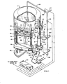
- FIG. 1 shows a perspective, partially cut-away, and fragmented view of cleaning apparatus made in accordance with the principles of the present invention; and
- FIG. 2 is a side, partially cut-away, fragmented elevational view of the apparatus of FIG. 1.
- Referring now to the drawings:
- Referring to the drawings, there is shown apparatus for automatically cleaning a conventional rotary filler of the type such as manufactured by Hema International, Inc. The rotary filler includes a generally cylindrical hopper 4 mounted to rotate about its cylindrical axis. The hopper is for holding flowable material such as baby foods, vegetable oil, wax, paints, etc., which is to be dispensed into containers.
- Mounted on the exterior of the hopper 4 are a plurality of spaced-apart filling assemblies 8, only one of which is shown in FIG. 1 and two of which are shown in FIG. 2. Each filling assembly includes a so-called
dosing cylinder 12 mounted onto afilling valve 16. so that the axis of thecylinder 12 is oriented to be generally vertical. Thevalve 16 is mounted on the side of the hopper 4 to communicate with the interior thereof. In particular, thevalve 16 may be operated to allow material contained in the hopper 4 to flow into thecylinder 12 or to allow material in thecylinder 12 to flow downwardly through the valve into a container or can disposed below the valve. The filling assembly 8 also includes apiston 20 mounted on the lower end of apiston rod 24 which, in turn, is slidably mounted in apiston guide sleeve 28. Thepiston guide sleeve 28 is mounted on the side of the hopper 4 to hold thepiston rod 24 in a generally vertical orientation so that the axis of the-rod is colinear with the axis of thecylinder 12. Thepiston rod 24 includes anelongate key 32 which fits into anelongate groove 36 formed in thesleeve 28 to prevent the piston rod from rotating in the sleeve. Thepiston guide sleeve 28 allows thepiston rod 24 to move upwardly or downwardly to enable removal of thepiston 20 from thecylinder 12 and reinsertion of the piston into the cylinder. FIG. 1 shows thepiston 20 completely removed from thecylinder 12, while FIG. 2 shows the piston in place within the cylinder. A spout 40 (FIG. 2) extends downwardly from thevalve 16 to guide material flowing from the cylinder and through the valve into a container or can disposed under the filling assembly. The conveyor system for positioning containers or cans under the filling assemblies is not shown since it forms no part of the present invention. - The
pistons 20 are caused to move in thecylinders 12 to alternately allow material to flow into the cylinders from the hopper and then from the cylinders into cans located under thevalves 16. The movement of thepistons 20 takes place automatically as the hopper and filling assemblies are rotated. The structure for controlling this movement of the pistons includes a pair oftracks tracks roller 52 which is mounted to rotate on anaxle 56 which extends outwardly from thepiston rod 24. Thetracks rollers 52 roll within thetracks rollers 52 are caused to move upwardly or downwardly, they cause thecorresponding piston rod 24 andpiston 20 to move upwardly or downwardly in thecorresponding cylinder 12. Thus, when thecylinder 12 is being filled, thecorresponding roller 52 is moving upwardly within thetracks piston 20, and when thecylinder 12 is being discharged of its contents, theroller 52 is moving downwardly within the tracks to cause thepiston 20 to move downwardly and force the material from the cylinder. Anelongate opening 30 in the front of the piston guide sleeve 28 accommodates vertical movement of theaxle 56. All of the above is conventional structure. - The apparatus of the present invention includes a pair of
lifting mechanisms 60 located on opposite sides of the hopper 4 by which thetracks oriented support posts base 66. A pair ofcollars posts braces collars tracks sleeves collars brace 80 extends between thecollar 68 andsleeve 76 and the col-lar 70 andsleeve 78. The openings in thesleeves worm screws worm screws platform 86 in which the screws are rotatably mounted. Theplatform 86, in turn, is rigidly mounted on theposts worm screws wheel gear 88 mounted at the lower end ofworm screw 84. As thewheel gear 88 is turnedf so also is theworm screw 84. As theworm screws sleeve collars tracks tracks rollers 52 will be carried upwardly to raise thepistons 20 up and out of thecorresponding cylinders 12. - Rotation of the
worm screws third worm screw 90 which is rotatably mounted under theplatform 86 to mesh with the two wheel gears mounted at the lower ends of theworm screws worm screw 90 is caused to rotate, the twoworm screws worm screw 90 is controlled by ahydraulic motor 92 which is coupled by way ofconduits 94 and 95 to abi-directiona1 valve 96. Thevalve 96, in turn, is coupled to a source of hydraulic fluid which is not shown. Thehydraulic motor 92 includes ashaft 98 on the end of which is mounted awheel gear 100 which is positioned in driving relationship with awheel gear 102 mounted on the end ofworm screw 90. Operation of the hydraulic 92 is under the control of acontrol unit 104 which produces various control signals for general control of the operation of the cleaning apparatus of the present invention. Thehydraulic motor 92 is controlled by thecontrol unit 104 operating thevalve 96 to allow hydraulic fluid to flow to the motor either through conduit 94 or throughconduit 95 to cause the motor to operate in either the-forward or backward directions. Thus, thehydraulic motor 92 can be controlled to rotateworm screw 90 in either direction to thereby cause the raising or lowering of thetracks pistons 20. - Cleaning of the rotary filler would be initiated by raising the pistons out of the corresponding cylinders so as to expose the pistons and cylinders to a spray of cleaning liquid. After cleaning, the pistons would again be lowered into place in the cylinders. To facilitate complete automation of this process, it is important that the pistons remain properly aligned with the cylinders during removal and reinsertion of the pistons in the cylinders. For this reason, piston guide sleeve 28 (and the other guide sleeves) is elongated to more precisely maintain the alignment of-the
piston 20 with thecylinder 12. It has been found advantageous to provide thepiston guide sleeve 28 which has a length which is about 1/4 or greater the distance over which thepiston 20 may be moved. To facilitate reinsertion of thepiston 20 into thecylinder 12, the upperinterior walls 14 of the cylinder are formed to slope or taper outwardly as best seen in FIG. 2. Thus, some misalignment of thepiston 20 with thecylinder 12 can be accommodated when the piston is being reinserted into the cylinder. - The cleaning liquid spraying apparatus of the embodiment of the drawings includes a
conduit 120 for conveying cleaning liquid under pressure from a source (not shown). Theconduit 120 divides into twobranches valves Conduit branch 124 extends through the top wall of the hopper 4 into the interior thereof. A spray nozzle .140 is mounted on the end of theconduit branch 124 to spray cleaning liquid in all directions inside the hopper 4 to clean the interior of the hopper. Thecontrol unit 104 signals controlvalve 132 to selectively and automatically open or close the valve to therby effectuate the cleaning of the hopper. - The
conduit branch 128 extends downwardly along the side of the hopper 4 and includes threespray nozzles pistons 20 which have been removed from their cylinders, and into the cylinders. Theconduit branch 128 also includesspray nozzles nozzles nozzles valve 16 to clean the exterior thereof and, if the valve has been opened, the interior. Anozzle 52 is connected to the end ofconduit branch 152 at a location belownozzles nozzles valve 136 in response to signals received from thecontrol unit 104. Excess liquid cleaner falls downwardly into a collecting pan 67 (FIG. 2) from which it is drained. - An exemplary sequence of operation for cleaning the rotary filler of the drawings could include the steps of the
control unit 104 signalling thevalve 96 to allow hydraulic fluid to flow to themotor 92 to cause the motor to operate thelifting mechanism 60 to lift thepistons 20 from thecylinders 12, the control unit signalling thecontrol valves 132 and 134 to allow cleaning fluid to flow to the spray nozzles, the control unit signalling aswitch 156 of a drive motor 160 (FIG. 2) of the rotary filler to cause the rotary filler with filling assemblies 8 to rotate past the spray nozzles, and then after a suitable time the control unit signalling the drive motor switch and controlvalves control unit 104 would signal thevalve 96 to allow hydraulic fluid to flow in the opposite direction to themotor 92 to cause the motor to operate the liftingmechanisms 60 to lower thepistons 20 back into thecylinders 12. - It is to be understood that the above-described arrangements are only illustrative of the application of the principles of the present invention. Numerous modifications and alternative arrangements may be devised by those skilled in the art without departing from the spirit and scope of the present invention and the appended claims are intended to cover such modifications and arrangements.
Claims (9)
Priority Applications (1)
| Application Number | Priority Date | Filing Date | Title |
|---|---|---|---|
| AT84112659T ATE29400T1 (en) | 1983-11-08 | 1984-10-19 | DEVICE AND METHOD FOR CLEANING FILLING FACILITIES FOR LIQUID SUBSTANCES. |
Applications Claiming Priority (2)
| Application Number | Priority Date | Filing Date | Title |
|---|---|---|---|
| US06/549,788 US4501622A (en) | 1983-11-08 | 1983-11-08 | Apparatus and method for cleaning flowable material filling devices |
| US549788 | 1983-11-08 |
Publications (2)
| Publication Number | Publication Date |
|---|---|
| EP0144662A1 true EP0144662A1 (en) | 1985-06-19 |
| EP0144662B1 EP0144662B1 (en) | 1987-09-09 |
Family
ID=24194387
Family Applications (1)
| Application Number | Title | Priority Date | Filing Date |
|---|---|---|---|
| EP84112659A Expired EP0144662B1 (en) | 1983-11-08 | 1984-10-19 | Apparatus and method for cleaning flowable material filling devices |
Country Status (6)
| Country | Link |
|---|---|
| US (1) | US4501622A (en) |
| EP (1) | EP0144662B1 (en) |
| JP (1) | JPS60123393A (en) |
| AT (1) | ATE29400T1 (en) |
| CA (1) | CA1240587A (en) |
| DE (1) | DE3465897D1 (en) |
Cited By (2)
| Publication number | Priority date | Publication date | Assignee | Title |
|---|---|---|---|---|
| CN103466526A (en) * | 2013-09-14 | 2013-12-25 | 苏州多贝机械科技有限公司 | UV (Ultraviolet Curing) paint filling device |
| EP2848580A1 (en) | 2013-09-11 | 2015-03-18 | Krones AG | Device for dosing a product into a container |
Families Citing this family (8)
| Publication number | Priority date | Publication date | Assignee | Title |
|---|---|---|---|---|
| US5095959A (en) * | 1988-05-26 | 1992-03-17 | Vacuum Engineering Corporation | Slide gate valve system for asbestos collection apparatus |
| US5348058A (en) * | 1992-11-06 | 1994-09-20 | National Instrument Company, Inc. | Clean-in-place filling machine |
| US5400927A (en) * | 1992-11-17 | 1995-03-28 | Marchadour; Jean C. | Liquid/flowable product filling apparatus with seal system |
| DE19741242C1 (en) * | 1997-09-18 | 1999-07-08 | Diversey Lever Gmbh | Plant for cleaning a bottling plant |
| DE102011008878A1 (en) * | 2011-01-18 | 2012-07-19 | Khs Gmbh | Filling element for container treatment machines in the form of filling machines, container treatment machine and method for cleaning machine elements on container treatment machines |
| DE102013109969A1 (en) * | 2013-09-11 | 2015-03-12 | Krones Ag | Device for dosing a filling product in a container to be filled |
| EP2965630B1 (en) | 2014-07-08 | 2016-12-07 | Albert Handtmann Maschinenfabrik GmbH & Co. KG | Filling machine and method for interim cleaning of a filling machine |
| CN107500221A (en) * | 2017-08-10 | 2017-12-22 | 苏州首达机械有限公司 | Can Rapid Cleaning filling apparatus |
Citations (2)
| Publication number | Priority date | Publication date | Assignee | Title |
|---|---|---|---|---|
| FR1213935A (en) * | 1957-11-14 | 1960-04-05 | Holstein & Kappert Maschf | Method and device for the sterile withdrawal of hot drinkable liquids containing carbonic acid, in particular beer |
| DE2321206B1 (en) * | 1973-04-26 | 1974-05-09 | Siegfried 8900 Augsburg Ammann | Dosing device for dosing liquid fillings, in particular food |
Family Cites Families (4)
| Publication number | Priority date | Publication date | Assignee | Title |
|---|---|---|---|---|
| US1254190A (en) * | 1916-04-19 | 1918-01-22 | Lewis A Baker | Filling-machine. |
| US2961013A (en) * | 1958-04-28 | 1960-11-22 | Texaco Inc | Positive displacement type fluid filling machine having automatic cam track adjustingmeans and method of filling |
| US2998037A (en) * | 1958-06-09 | 1961-08-29 | Bingham David William | Can filling apparatus |
| US3568734A (en) * | 1965-06-07 | 1971-03-09 | Fmc Corp | Carton-filling apparatus |
-
1983
- 1983-11-08 US US06/549,788 patent/US4501622A/en not_active Expired - Lifetime
-
1984
- 1984-10-15 CA CA000465405A patent/CA1240587A/en not_active Expired
- 1984-10-19 AT AT84112659T patent/ATE29400T1/en not_active IP Right Cessation
- 1984-10-19 DE DE8484112659T patent/DE3465897D1/en not_active Expired
- 1984-10-19 EP EP84112659A patent/EP0144662B1/en not_active Expired
- 1984-11-07 JP JP59233384A patent/JPS60123393A/en active Granted
Patent Citations (2)
| Publication number | Priority date | Publication date | Assignee | Title |
|---|---|---|---|---|
| FR1213935A (en) * | 1957-11-14 | 1960-04-05 | Holstein & Kappert Maschf | Method and device for the sterile withdrawal of hot drinkable liquids containing carbonic acid, in particular beer |
| DE2321206B1 (en) * | 1973-04-26 | 1974-05-09 | Siegfried 8900 Augsburg Ammann | Dosing device for dosing liquid fillings, in particular food |
Cited By (4)
| Publication number | Priority date | Publication date | Assignee | Title |
|---|---|---|---|---|
| EP2848580A1 (en) | 2013-09-11 | 2015-03-18 | Krones AG | Device for dosing a product into a container |
| CN104417792A (en) * | 2013-09-11 | 2015-03-18 | 克罗内斯股份公司 | Device for dosing a filling product into a container to be filled |
| DE102013109968A1 (en) | 2013-09-11 | 2015-03-26 | Krones Ag | Device for dosing a filling product in a container to be filled |
| CN103466526A (en) * | 2013-09-14 | 2013-12-25 | 苏州多贝机械科技有限公司 | UV (Ultraviolet Curing) paint filling device |
Also Published As
| Publication number | Publication date |
|---|---|
| EP0144662B1 (en) | 1987-09-09 |
| ATE29400T1 (en) | 1987-09-15 |
| CA1240587A (en) | 1988-08-16 |
| US4501622A (en) | 1985-02-26 |
| JPH0517117B2 (en) | 1993-03-08 |
| DE3465897D1 (en) | 1987-10-15 |
| JPS60123393A (en) | 1985-07-02 |
Similar Documents
| Publication | Publication Date | Title |
|---|---|---|
| US4501622A (en) | Apparatus and method for cleaning flowable material filling devices | |
| US7024988B2 (en) | Plant for the continuous processing and packing of meat products | |
| US6053219A (en) | Apparatus and method for filling containers with liquid | |
| JPH11115904A (en) | Equipment for metering and filling products from liquid to pasty, especially multi-line sterile machines and container filling methods | |
| US7143793B2 (en) | Cleaning system for a filling machine | |
| EP2848580B1 (en) | Device for dosing a product into a container | |
| US4602964A (en) | Valve removal and cleaning system for container filling apparatus | |
| JPH0834491A (en) | Device to empty rotary symmetrical container with mouth | |
| US2418691A (en) | Machine for emptying and washing containers | |
| US5829493A (en) | Apparatus for filling containers with a liquid | |
| US4834589A (en) | Apparatus and process for transferring pulverent material from a supply container to a delivery point | |
| DE69605962T2 (en) | Device for producing mixtures, in particular dye solutions | |
| EP1475325B1 (en) | Device for dosing bulk material components | |
| CA1315750C (en) | Method and apparatus for dispensing liquids | |
| US7328652B2 (en) | Apparatus and system for dispensing dough | |
| US5494085A (en) | Container filling apparatus | |
| DE60033361T2 (en) | Beverage vending machine with improved arrangement for displacing the dispensing nozzles | |
| EP0728667A1 (en) | Liquid filling apparatus and method | |
| RU2048434C1 (en) | Liquid filling machine | |
| EP0074418A1 (en) | Liquid dispensing machine | |
| EP0578265B1 (en) | Metering device for preparing dosed mixtures of chemical products | |
| US2763417A (en) | Filling machine | |
| CN223175824U (en) | Paste seasoning efficient filling machine | |
| EP0159051A2 (en) | Machine for dispensing liquid and semiliquid material | |
| CA1158616A (en) | Variable volume, positive displacement sanitary liquid dispensing machine |
Legal Events
| Date | Code | Title | Description |
|---|---|---|---|
| PUAI | Public reference made under article 153(3) epc to a published international application that has entered the european phase |
Free format text: ORIGINAL CODE: 0009012 |
|
| AK | Designated contracting states |
Designated state(s): AT BE CH DE FR GB IT LI NL SE |
|
| 17P | Request for examination filed |
Effective date: 19851009 |
|
| 17Q | First examination report despatched |
Effective date: 19860714 |
|
| GRAA | (expected) grant |
Free format text: ORIGINAL CODE: 0009210 |
|
| AK | Designated contracting states |
Kind code of ref document: B1 Designated state(s): AT BE CH DE FR GB IT LI NL SE |
|
| PG25 | Lapsed in a contracting state [announced via postgrant information from national office to epo] |
Ref country code: NL Effective date: 19870909 Ref country code: LI Effective date: 19870909 Ref country code: IT Free format text: LAPSE BECAUSE OF FAILURE TO SUBMIT A TRANSLATION OF THE DESCRIPTION OR TO PAY THE FEE WITHIN THE PRESCRIBED TIME-LIMIT;WARNING: LAPSES OF ITALIAN PATENTS WITH EFFECTIVE DATE BEFORE 2007 MAY HAVE OCCURRED AT ANY TIME BEFORE 2007. THE CORRECT EFFECTIVE DATE MAY BE DIFFERENT FROM THE ONE RECORDED. Effective date: 19870909 Ref country code: CH Effective date: 19870909 Ref country code: BE Effective date: 19870909 Ref country code: AT Effective date: 19870909 |
|
| REF | Corresponds to: |
Ref document number: 29400 Country of ref document: AT Date of ref document: 19870915 Kind code of ref document: T |
|
| PG25 | Lapsed in a contracting state [announced via postgrant information from national office to epo] |
Ref country code: SE Effective date: 19870930 |
|
| REF | Corresponds to: |
Ref document number: 3465897 Country of ref document: DE Date of ref document: 19871015 |
|
| ET | Fr: translation filed | ||
| REG | Reference to a national code |
Ref country code: CH Ref legal event code: PL |
|
| NLV1 | Nl: lapsed or annulled due to failure to fulfill the requirements of art. 29p and 29m of the patents act | ||
| PLBE | No opposition filed within time limit |
Free format text: ORIGINAL CODE: 0009261 |
|
| STAA | Information on the status of an ep patent application or granted ep patent |
Free format text: STATUS: NO OPPOSITION FILED WITHIN TIME LIMIT |
|
| 26N | No opposition filed | ||
| PGFP | Annual fee paid to national office [announced via postgrant information from national office to epo] |
Ref country code: GB Payment date: 19990208 Year of fee payment: 15 Ref country code: FR Payment date: 19990208 Year of fee payment: 15 |
|
| PGFP | Annual fee paid to national office [announced via postgrant information from national office to epo] |
Ref country code: DE Payment date: 19990225 Year of fee payment: 15 |
|
| PG25 | Lapsed in a contracting state [announced via postgrant information from national office to epo] |
Ref country code: GB Free format text: LAPSE BECAUSE OF NON-PAYMENT OF DUE FEES Effective date: 19991019 |
|
| GBPC | Gb: european patent ceased through non-payment of renewal fee |
Effective date: 19991019 |
|
| PG25 | Lapsed in a contracting state [announced via postgrant information from national office to epo] |
Ref country code: FR Free format text: LAPSE BECAUSE OF NON-PAYMENT OF DUE FEES Effective date: 20000630 |
|
| PG25 | Lapsed in a contracting state [announced via postgrant information from national office to epo] |
Ref country code: DE Free format text: LAPSE BECAUSE OF NON-PAYMENT OF DUE FEES Effective date: 20000801 |
|
| REG | Reference to a national code |
Ref country code: FR Ref legal event code: ST |