EP0144623B1 - Machine for making a double strip enclosing packets of ground coffee - Google Patents
Machine for making a double strip enclosing packets of ground coffee Download PDFInfo
- Publication number
- EP0144623B1 EP0144623B1 EP84112168A EP84112168A EP0144623B1 EP 0144623 B1 EP0144623 B1 EP 0144623B1 EP 84112168 A EP84112168 A EP 84112168A EP 84112168 A EP84112168 A EP 84112168A EP 0144623 B1 EP0144623 B1 EP 0144623B1
- Authority
- EP
- European Patent Office
- Prior art keywords
- coffee
- carrier
- station
- conveyor
- web
- Prior art date
- Legal status (The legal status is an assumption and is not a legal conclusion. Google has not performed a legal analysis and makes no representation as to the accuracy of the status listed.)
- Expired
Links
Images



Classifications
-
- B—PERFORMING OPERATIONS; TRANSPORTING
- B65—CONVEYING; PACKING; STORING; HANDLING THIN OR FILAMENTARY MATERIAL
- B65B—MACHINES, APPARATUS OR DEVICES FOR, OR METHODS OF, PACKAGING ARTICLES OR MATERIALS; UNPACKING
- B65B9/00—Enclosing successive articles, or quantities of material, e.g. liquids or semiliquids, in flat, folded, or tubular webs of flexible sheet material; Subdividing filled flexible tubes to form packages
- B65B9/02—Enclosing successive articles, or quantities of material between opposed webs
- B65B9/04—Enclosing successive articles, or quantities of material between opposed webs one or both webs being formed with pockets for the reception of the articles, or of the quantities of material
- B65B9/042—Enclosing successive articles, or quantities of material between opposed webs one or both webs being formed with pockets for the reception of the articles, or of the quantities of material for fluent material
-
- A—HUMAN NECESSITIES
- A23—FOODS OR FOODSTUFFS; TREATMENT THEREOF, NOT COVERED BY OTHER CLASSES
- A23F—COFFEE; TEA; THEIR SUBSTITUTES; MANUFACTURE, PREPARATION, OR INFUSION THEREOF
- A23F5/00—Coffee; Coffee substitutes; Preparations thereof
- A23F5/10—Treating roasted coffee; Preparations produced thereby
- A23F5/12—Agglomerating, flaking or tabletting
- A23F5/125—Tablets or other similar solid forms
-
- B—PERFORMING OPERATIONS; TRANSPORTING
- B65—CONVEYING; PACKING; STORING; HANDLING THIN OR FILAMENTARY MATERIAL
- B65B—MACHINES, APPARATUS OR DEVICES FOR, OR METHODS OF, PACKAGING ARTICLES OR MATERIALS; UNPACKING
- B65B29/00—Packaging of materials presenting special problems
- B65B29/02—Packaging of substances, e.g. tea, which are intended to be infused in the package
- B65B29/025—Packaging of substances, e.g. tea, which are intended to be infused in the package packaging infusion material into pods
Definitions
- the invention concerns a machine for making a double strip in which packets of ground coffee are spaced at intervals.
- the apparatus comprises means for feeding in the lower web, the ground coffee and the upper web.
- the third_patent concerns an apparatus comprising a closed-link chain moving in a horizontal plane each link of which consists of two plates joined by a hinge, the lower plate containing an impression, substantially corresponding to the lower half of a batch of ground coffee, and an upper plate having an opening opposite said impression for passage of means for forming a complete packet, each lower plate being hinged to the two adjacent lower plates along two transversal edges; each pair of plates serves as a base for forming a packet when said pair of plates reaches the first series of stations on a first straight path of the chain and the second series of stations along a second straight path of the chain.
- Means are provided for feeding in the lower web, the ground coffee and the upper web; each set of stations includes one at which an impression is formed for the coffee in the lower web, another station at which a batch of coffee is deposited in said impression, another at which the batch is flattened, another at which the flattened batch is compressed to form a compacted coffee pad, another at which the upper web is bonded to the lower web around the compacted pad, and another at which the completed strip is perforated along its edges.
- the machine with the characterizing features of Claim 1 is intended to remedy these drawbacks. It solves the problem of producing a double strip of permeable material in which packets of ground coffee are incorporated, spaced at intervals, so that said strip may be used in an automatic coffee machine or each single coffee packet may be used in a coffee machine adapted to be fed by single coffee packets.
- the advantages of the machine constructed according to the invention are mainly that the machine has compact size, provides for accurate size and weight of the coffee pockets as well as for continuity and precision of production due to the machine's automatic cleaning devices.
- Fig. 1 indicates a means 1 holding a roll of water-permeable material for forming a lower web, and a device for paying out said web; a position 2 where the lower web is laid on the lower of a pair of plates in the conveyor 16; a station 3 at which a pocket is formed in the lower web for receiving a batch of ground coffee shaped to form a circular pad; a reservoir 4 holding ground coffee; a volumetric batching device 5 for metering a batch of ground coffee; a duct 6 through which the batch of ground coffee falls into said pocket; a preliminary compressing station 8 for flattening a batch of ground coffee; a final compacting station 9 for the previously pressed batch of coffee; a suction station 10 for cleaning off coffee particles remaining on the coffee pad and on the lower web around it; a means 11 holding a roll of water-permeable material for forming an upper web and a device for paying it out; a position 12 at which the upper web is laid over a lower plate and over a coffee pad formed in the lower web;
- Fig. 2 shows the chain 16 composed of paired plates 20 each pair having a lower plate 21 and an upper plate 22.
- the lower plates 21 are hinged to each other at 23 crosswise to chain movement the upper surface of each lower plate comprising a circular impression 24 which serves to shape the lower web of water-permeable material like a pocket into which a metered batch of ground coffee will be deposited; a number of holes 25 are bored in the depression 24 in the lower plate 21, directly opposite the aperture 27 in the upper plate, through which holes air is drawn to keep the lower web adhering closely to the lower plate.
- the upper plates 22, hinged to the lower plates at 26, parallel with the chain, each have a circular opening 27 opposite the impression 24 in the lower plate; the diameter of aperture 27 is suitably larger than that of the impression.
- the conveyor chain 16 lies in, and slides along, the bed 30 (see Fig. 3 also) in which a groove 31 is cut and is kept depressurized by conventional means, not shown, so that air is drawn in through the holes 25 in the lower plates 21.
- Fig. 3 shows a carrier 40 each end of which is connected by two links 41 to a driven gear 42.
- a driver gear 43 meshes with a driven gear 42 and, on the right, an intermittent gear 43/A meshes with a similar driven gear 42 at the other end.
- Diameters of gears 42 are the same as are also, though larger, those of the drive gear 43 and the intermittent gear 43/A.
- a prime mover not shown, imparts a continuous rotary movement to gear 43 whose speed may be varied by conventional means. Rotating speeds of the two gears 42 are equal though they rotate in opposite directions.
- the figure shows that, along the inner perimeter of conveyor 16, a chain 101 is fixed and meshes with sprocket wheel 102 on whose shaft a ratchet wheel 103 is mounted.
- a chain 101 is fixed and meshes with sprocket wheel 102 on whose shaft a ratchet wheel 103 is mounted.
- an intermittent rotary movement is imparted to sprocket wheel 102 that draws the conveyor 16.
- Carrier 40 is also guided by four guides 44 (two only can be seen in the Figure) that pass through holes in the carrier.
- the carrier is equipped with a set of tools for forming the coffee packets: means 45 shaped so as to fit into the impression in the lower plates 21 and form a similar impression in the lower web; a duct 6 down which a metered batch of ground coffee falls when the conveyor 16 stops; a presser 47 that flattens and initially compresses the batch of coffee in an impression; a final compacting tool 48 that compacts the already pressed batch of coffee under a force of 5000 N and rotates about its vertical axis when, while rising, the force on the coffee pad is lessened to about 1300 N as will be explained in detail when describing Figs.
- FIG. 3 further shows a means 1 for holding a roll of water-permeable paper for the lower web and another for paying out the web; a lower water-permeable web 55 is laid on a lower plate by a controlled loop system; a reser- vair 4 containing ground coffee; a metering device 5 for discharging a batch of ground coffee into a duct 6; a suction-generating device 56 for drawing in air, through the flexible tube 57 and rigid pipe 58, into the lower intake end of nozzle 49; a means 11 for holding a roll of water-permeable paper for the upper web and a device for paying the web out; a roll of water-permeable paper for the upper web 59 which, by means of a controlled loop system, is laid over a coffee pad formed in a lower plate.
- Figs. 4 and 5 show the final compacting tool mounted on the vertical shaft 65 coupled to the shaft 66 by a thrust bearing 67 enabling shaft 65 to rotate in relation to shaft 66.
- the upper end of shaft 66 carries a piston 68 inside a pneumatic cylinder 69 fixed to the carrier 40, not shown, by a holding means 70; cylinder 69 communicates with a source 71 of compressed air through a conduit containing an adjustable pressure reducing valve 72 and a pressure gauge 73; shaft 65 can slide up and down within the bearings 74 fixed to the carrier 40; shaft 65 carries a pinion 76 whose teeth mesh with rack 77; the shaft 78 of rack 77 is connected to a piston 79 inside a pneumatic cylinder 80; at each end the pneumatic cylinder 80 is connected to a duct 81, 82 on which is mounted a distributor valve 83 receiving compressed air from a source not shown.
- the assembly illustrated in Figs. 4 and 5 operates as follows: when the carrier 40 is raised above the conveyor 16, the piston 68 is against the lowermost part of the cylinder 69 in which pressure is maintained at a certain level; during descent of the carrier 40 towards the conveyor 16, there is a pause when the lower surface of the compactor 48 further presses the coffee pad and, as the carrier 40 continues downwards and the piston 68 rises, pressure in the pneumatic cylinder increases to a force of 5000 N applied to the coffee pad. Maximum pressure in the pneumatic cylinder 69 also depends on the pressure level permanently maintained in the pneumatic cylinder when the piston is fully lowered, such pressure being watched by gauge 73.
- Fig. 6 illustrates a reservoir 4 for ground coffee fitted with a photoelectric cell 120 for monitoring the level of the ground coffee 121; when the level of the coffee in reservoir 4 falls below a certain point, the photoelectric cell 120 operates a small grinder, not shown, upstream of reservoir 4, by conventional means, not shown, which grinder works for a predetermined time to grind an adequate quantity of coffee. Conventional means, not shown, operate the volumetric metering device 5 whenever the conveyor 16 stops.
- Fig. 7 shows the chamber 122 of the metering device 5 comprising an intermittently rotatable wheel 123 with curved blades, and an area 124 defined by an aperture 125 in the chamber, by its two sides 126 and gate 127 adjustable by a micrometric screw 128.
- the wheel rotates, as indicated by arrow F3, for a predetermined time, the quantity of coffee passing into duct 6 depends on the position given to gate 127, the micrometric screw enabling very accurate adjustment to be made.
- Fig. 8 shows the two electrodes 130, 131 in the duct 6 situated downstream of the metering device 5; these electrodes maintain a potential difference, monitored by voltmeter 132, sufficient to de-ionize the coffee particles inside the duct and prevent them from adhering to its internal surface.
- Fig. 9 shows a bonding station 50 associated to shaft 151 by a ball joint.
- the working surface 152 of the bonding device 50 contains raised portions 153; below the bonding device 50 a pair of plates stand waiting.
- a compressed coffee pad 154 has been formed on the lower web 55; the upper web 59 is laid over the coffee pad.
- the bonding device is lowered to press the upper web onto the coffee pad that protrudes above the lower plate and to bond the upper and lower webs together all round the coffee pad to complete formation of a coffee packet.
- Fig. 10 shows a suction nozzle 49 and a pair of plates 20 waiting below the nozzle, in the lower plate of which a coffee packet has been formed in the preceding stations; air is drawn in through conduit 58 so that any loose particles of coffee lying on the coffee packet and on the web adjacent to it are sucked up by the nozzle 49 through the holes 160.
Landscapes
- Engineering & Computer Science (AREA)
- Mechanical Engineering (AREA)
- Life Sciences & Earth Sciences (AREA)
- Chemical & Material Sciences (AREA)
- Food Science & Technology (AREA)
- Polymers & Plastics (AREA)
- Tea And Coffee (AREA)
- Containers And Plastic Fillers For Packaging (AREA)
- Basic Packing Technique (AREA)
Description
- The invention concerns a machine for making a double strip in which packets of ground coffee are spaced at intervals.
- The U.S. Patents Nos.. 3,186,137 and 3,293,042 to Eitzen and the U.S. Patent No. 3,186,139 to Claus cover certain apparatuses for making continuous strips enclosing batches of ground coffee. The first two patents are issued for an apparatus comprising two independent closed chains moveable in vertical planes, each chain comprising a number of plates serving as supports for depositing metered batches of ground coffee onto a lower web of water-permeable material; said batches are then compressed to form compact coffee pads over and around which an upper layer of water-permeable web is bonded to the lower web so that the compacted coffee pad becomes tightly enclosed within the two webs, the process continuing until a strip is formed in which flat disc-shaped packets of ground coffee are spaced at regular intervals. The apparatus comprises means for feeding in the lower web, the ground coffee and the upper web. The third_patent concerns an apparatus comprising a closed-link chain moving in a horizontal plane each link of which consists of two plates joined by a hinge, the lower plate containing an impression, substantially corresponding to the lower half of a batch of ground coffee, and an upper plate having an opening opposite said impression for passage of means for forming a complete packet, each lower plate being hinged to the two adjacent lower plates along two transversal edges; each pair of plates serves as a base for forming a packet when said pair of plates reaches the first series of stations on a first straight path of the chain and the second series of stations along a second straight path of the chain. Means are provided for feeding in the lower web, the ground coffee and the upper web; each set of stations includes one at which an impression is formed for the coffee in the lower web, another station at which a batch of coffee is deposited in said impression, another at which the batch is flattened, another at which the flattened batch is compressed to form a compacted coffee pad, another at which the upper web is bonded to the lower web around the compacted pad, and another at which the completed strip is perforated along its edges.
- Drawbacks to the apparatus according to the first two patent references are that there is too much variation in the sizes and weights of the coffee packets, and that the row of coffee packets in a strip are not equally compacted.
- Drawbacks to the apparatus according to the third patent US-A-3,186,139, from which Claim 1 starts, reference are: the ground coffee to make each packet is not accurately metered, the upper surface of the strip is contaminated by coffee particles adhering to the tools that compact the pads, the apparatus is too bulky while its output is relatively low since the stations on the two straight paths cannot operate simultaneously as those on one path must remain idle while plates are cleaned, inaccurate operation due to undesirable movements caused by the centre of a carrier being connected to means for transmitting a reciprocating movement and being guided solely by four rods passing through holes at its enqs.
- According to the invention the machine with the characterizing features of Claim 1 is intended to remedy these drawbacks. It solves the problem of producing a double strip of permeable material in which packets of ground coffee are incorporated, spaced at intervals, so that said strip may be used in an automatic coffee machine or each single coffee packet may be used in a coffee machine adapted to be fed by single coffee packets.
- The advantages of the machine constructed according to the invention are mainly that the machine has compact size, provides for accurate size and weight of the coffee pockets as well as for continuity and precision of production due to the machine's automatic cleaning devices.
- The invention will now be described making reference to the accompanying drawings, which however show only one embodiment of the invention, wherein:
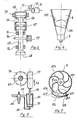
- Fig. 1 is a diagrammatic layout of the main parts of the machine,
- Fig. 2 is a partial view of two plates forming the conveyor,
- Fig. 3 shows the positions of the main parts of the machine,
- Fig. 4 is a drawing of the presser at the final compacting station,
- Fig. 5 is a partial cross section V-V in Fig. 4,
- Fig. 6 is a drawing of the ground coffee reservoir associated to a volumetric batcher,
- Fig. 7 is a plan view of the metering device,
- Fig. 8 is a drawing of the duct through which coffee is deposited in a pocket,
- Fig. 9 is a drawing of the bonding station for forming coffee packets,
- Fig. 10 is a view of the means for cleaning off loose coffee particles.
- Fig. 1 indicates a means 1 holding a roll of water-permeable material for forming a lower web, and a device for paying out said web; a
position 2 where the lower web is laid on the lower of a pair of plates in theconveyor 16; astation 3 at which a pocket is formed in the lower web for receiving a batch of ground coffee shaped to form a circular pad; areservoir 4 holding ground coffee; avolumetric batching device 5 for metering a batch of ground coffee; aduct 6 through which the batch of ground coffee falls into said pocket; a preliminary compressing station 8 for flattening a batch of ground coffee; afinal compacting station 9 for the previously pressed batch of coffee; asuction station 10 for cleaning off coffee particles remaining on the coffee pad and on the lower web around it; ameans 11 holding a roll of water-permeable material for forming an upper web and a device for paying it out; aposition 12 at which the upper web is laid over a lower plate and over a coffee pad formed in the lower web; abonding station 13 where the upper web is pressed over that part of the coffee pad emerging above the surface of the lower plate and is bonded to the surrounding lower web to form acoffee packet 155 in astrip 255; astation 14 where the shape of the coffee packet is monitored and where information is encoded onto the strip formed by the bonded webs; astation 15 where the completed strip is cut into lengths each length containing a certain number of coffee packets; anendless conveyor chain 16 consisting of paired plates moving in a vertical plane, the upper chain moving in the direction indicated by the arrow F1, the upper plates being raised from the lower ones in length A and closed down on them in length B. - Fig. 2 shows the
chain 16 composed of pairedplates 20 each pair having alower plate 21 and anupper plate 22. Thelower plates 21 are hinged to each other at 23 crosswise to chain movement the upper surface of each lower plate comprising acircular impression 24 which serves to shape the lower web of water-permeable material like a pocket into which a metered batch of ground coffee will be deposited; a number ofholes 25 are bored in thedepression 24 in thelower plate 21, directly opposite theaperture 27 in the upper plate, through which holes air is drawn to keep the lower web adhering closely to the lower plate. Theupper plates 22, hinged to the lower plates at 26, parallel with the chain, each have acircular opening 27 opposite theimpression 24 in the lower plate; the diameter ofaperture 27 is suitably larger than that of the impression. - The
conveyor chain 16 lies in, and slides along, the bed 30 (see Fig. 3 also) in which agroove 31 is cut and is kept depressurized by conventional means, not shown, so that air is drawn in through theholes 25 in thelower plates 21. - Fig. 3 shows a
carrier 40 each end of which is connected by twolinks 41 to a drivengear 42. On the left a driver gear 43 meshes with a drivengear 42 and, on the right, an intermittent gear 43/A meshes with a similar drivengear 42 at the other end. Diameters ofgears 42 are the same as are also, though larger, those of the drive gear 43 and the intermittent gear 43/A. A prime mover, not shown, imparts a continuous rotary movement to gear 43 whose speed may be varied by conventional means. Rotating speeds of the twogears 42 are equal though they rotate in opposite directions. When in operation, the above assembly keeps thecarrier 40 moving up and down in relation to the upperhorizontal conveyor chain 16. The conveyor advances intermittently due to oscillation oflink 41 connected to theleft gear 42. - The figure shows that, along the inner perimeter of
conveyor 16, achain 101 is fixed and meshes withsprocket wheel 102 on whose shaft aratchet wheel 103 is mounted. By means of the twolinks pawl 106 an intermittent rotary movement is imparted to sprocketwheel 102 that draws theconveyor 16. -
Carrier 40 is also guided by four guides 44 (two only can be seen in the Figure) that pass through holes in the carrier. The carrier is equipped with a set of tools for forming the coffee packets: means 45 shaped so as to fit into the impression in thelower plates 21 and form a similar impression in the lower web; aduct 6 down which a metered batch of ground coffee falls when theconveyor 16 stops; apresser 47 that flattens and initially compresses the batch of coffee in an impression; afinal compacting tool 48 that compacts the already pressed batch of coffee under a force of 5000 N and rotates about its vertical axis when, while rising, the force on the coffee pad is lessened to about 1300 N as will be explained in detail when describing Figs. 4 and 5; anozzle 49 for sucking in air from the upper surface of the coffee pad and from its adjacent web; abonding device 50 that shapes the upper web closely round the coffee pad and bonds the adjacent portions of the upper web to those of the lower web; aquality detector 51 which monitors the dimensions of that part of the coffee packet protruding above the lower plate; asevering tool 52 all of whose vertical movements are made simultaneously with those of thecarrier 40, and which is associated to amobile blade 53 that rises up to co-operate with thetool 52 and cuts a tape, this movement being controlled by a packet meter not shown. Fig. 3 further shows a means 1 for holding a roll of water-permeable paper for the lower web and another for paying out the web; a lower water-permeable web 55 is laid on a lower plate by a controlled loop system; a reser-vair 4 containing ground coffee; ametering device 5 for discharging a batch of ground coffee into aduct 6; a suction-generatingdevice 56 for drawing in air, through theflexible tube 57 andrigid pipe 58, into the lower intake end ofnozzle 49; ameans 11 for holding a roll of water-permeable paper for the upper web and a device for paying the web out; a roll of water-permeable paper for theupper web 59 which, by means of a controlled loop system, is laid over a coffee pad formed in a lower plate. Conventional means, not shown, hold theupper plates 22 in a raised position over thelower plates 21 along a length of conveyor as illustrated in the Figure. It will be clear that themeans brake 61 locks thegear 62 of theconveyor 16 to stop the conveyor when its intermittent motion ceases. This brake is provided to allow the pairedplates 20 in the upper horizontal path of the conveyor to close up together, each pair touching the ones adjacent to it, in order to prevent any movement between the paired plates that could affect the paper strips and cause inaccurate packet formation. - Figs. 4 and 5 show the final compacting tool mounted on the
vertical shaft 65 coupled to theshaft 66 by a thrust bearing 67 enablingshaft 65 to rotate in relation toshaft 66. The upper end ofshaft 66 carries apiston 68 inside apneumatic cylinder 69 fixed to thecarrier 40, not shown, by aholding means 70;cylinder 69 communicates with a source 71 of compressed air through a conduit containing an adjustable pressure reducing valve 72 and apressure gauge 73;shaft 65 can slide up and down within thebearings 74 fixed to thecarrier 40;shaft 65 carries apinion 76 whose teeth mesh withrack 77; theshaft 78 ofrack 77 is connected to apiston 79 inside apneumatic cylinder 80; at each end thepneumatic cylinder 80 is connected to aduct distributor valve 83 receiving compressed air from a source not shown. The assembly illustrated in Figs. 4 and 5 operates as follows: when thecarrier 40 is raised above theconveyor 16, thepiston 68 is against the lowermost part of thecylinder 69 in which pressure is maintained at a certain level; during descent of thecarrier 40 towards theconveyor 16, there is a pause when the lower surface of thecompactor 48 further presses the coffee pad and, as thecarrier 40 continues downwards and thepiston 68 rises, pressure in the pneumatic cylinder increases to a force of 5000 N applied to the coffee pad. Maximum pressure in thepneumatic cylinder 69 also depends on the pressure level permanently maintained in the pneumatic cylinder when the piston is fully lowered, such pressure being watched bygauge 73. - Maximum pressure is reached in the
pneumatic cylinder 69 when thecarrier 40 arrives at its lowest position; the carrier then begins to rise and pressure in thepneumatic cylinder 69 to fall; a conventional device, not shown, comes into operation as thecarrier 40 starts to rise in order to supply compressed air to thepneumatic cylinder 80, upstream ofpiston 79, throughpipe 81; compressed air pressure is adapted to impart sufficient force and motion to rack 77, as indicated by arrow F2, so that through pinion 76 a torque moment is applied toshaft 65 and this is initially unable to overcome the resistance set up by a combination of friction between the underside of the compactor and the coffee pad with said force at 5000 N but while thecarrier 40 rises, said resistance can be overcome as force falls to about 1300 N. The underside of the compactor then rotates in relation to the surface of the coffee pad thus freeing itself of any coffee particles. While the compactor rotates,piston 79 reaches the end of its stroke at which point a conventional device, not shown, opens the outlet ofdistributor valve 83 and delivers compressed air tocylinder 80 throughconduit 82 downstream ofpiston 79 allowing the latter to return to its starting position. - Fig. 6 illustrates a
reservoir 4 for ground coffee fitted with aphotoelectric cell 120 for monitoring the level of theground coffee 121; when the level of the coffee inreservoir 4 falls below a certain point, thephotoelectric cell 120 operates a small grinder, not shown, upstream ofreservoir 4, by conventional means, not shown, which grinder works for a predetermined time to grind an adequate quantity of coffee. Conventional means, not shown, operate thevolumetric metering device 5 whenever theconveyor 16 stops. - Fig. 7 shows the
chamber 122 of themetering device 5 comprising an intermittentlyrotatable wheel 123 with curved blades, and anarea 124 defined by anaperture 125 in the chamber, by its twosides 126 andgate 127 adjustable by amicrometric screw 128. When the wheel rotates, as indicated by arrow F3, for a predetermined time, the quantity of coffee passing intoduct 6 depends on the position given togate 127, the micrometric screw enabling very accurate adjustment to be made. - Fig. 8 shows the two
electrodes duct 6 situated downstream of themetering device 5; these electrodes maintain a potential difference, monitored byvoltmeter 132, sufficient to de-ionize the coffee particles inside the duct and prevent them from adhering to its internal surface. - Fig. 9 shows a
bonding station 50 associated toshaft 151 by a ball joint. Theworking surface 152 of thebonding device 50 contains raisedportions 153; below the bonding device 50 a pair of plates stand waiting. In the impression in the lower plate 21 acompressed coffee pad 154 has been formed on thelower web 55; theupper web 59 is laid over the coffee pad. The bonding device is lowered to press the upper web onto the coffee pad that protrudes above the lower plate and to bond the upper and lower webs together all round the coffee pad to complete formation of a coffee packet. - Fig. 10 shows a
suction nozzle 49 and a pair ofplates 20 waiting below the nozzle, in the lower plate of which a coffee packet has been formed in the preceding stations; air is drawn in throughconduit 58 so that any loose particles of coffee lying on the coffee packet and on the web adjacent to it are sucked up by thenozzle 49 through theholes 160.
Claims (3)
Applications Claiming Priority (2)
| Application Number | Priority Date | Filing Date | Title |
|---|---|---|---|
| IT23345/83A IT1169585B (en) | 1983-10-18 | 1983-10-18 | MACHINE TO PRODUCE A CONTINUOUS TAPE BEARING COFFEE PODS FOR AN AUTOMATIC ESPRESSO COFFEE MACHINE |
| IT2334583 | 1983-10-18 |
Publications (3)
| Publication Number | Publication Date |
|---|---|
| EP0144623A2 EP0144623A2 (en) | 1985-06-19 |
| EP0144623A3 EP0144623A3 (en) | 1986-06-25 |
| EP0144623B1 true EP0144623B1 (en) | 1988-12-28 |
Family
ID=11206272
Family Applications (1)
| Application Number | Title | Priority Date | Filing Date |
|---|---|---|---|
| EP84112168A Expired EP0144623B1 (en) | 1983-10-18 | 1984-10-11 | Machine for making a double strip enclosing packets of ground coffee |
Country Status (6)
| Country | Link |
|---|---|
| US (1) | US4555894A (en) |
| EP (1) | EP0144623B1 (en) |
| JP (1) | JPS6099808A (en) |
| CA (1) | CA1220409A (en) |
| DE (1) | DE3475767D1 (en) |
| IT (1) | IT1169585B (en) |
Families Citing this family (28)
| Publication number | Priority date | Publication date | Assignee | Title |
|---|---|---|---|---|
| IT1213385B (en) * | 1986-11-25 | 1989-12-20 | Illycaffe Spa | METHOD TO PRODUCE A GROUND COFFEE DISCOID TO EXTRACT AN EXPRESS COFFEE. |
| US5012629A (en) * | 1989-10-11 | 1991-05-07 | Kraft General Foods, Inc. | Method for producing infusion coffee filter packs |
| GB2237258B (en) * | 1989-10-26 | 1993-10-20 | American Cyanamid Co | Apparatus and method for manufacturing soft shell capsules |
| US5074102A (en) * | 1989-10-26 | 1991-12-24 | American Cyanamid Company | Flat track modified soft shell capsule filling machine |
| EP1107911B1 (en) | 1998-03-09 | 2005-01-19 | Cima Labs Inc. | Apparatus for handling and packaging friable tablets |
| US6758130B2 (en) | 2001-03-16 | 2004-07-06 | The Procter + Gamble Co. | Beverage brewing devices for preparing creamy beverages |
| US20040045443A1 (en) * | 2002-06-19 | 2004-03-11 | Lazaris Nicholas G. | Disposable beverage filter package |
| US7640843B2 (en) | 2003-01-24 | 2010-01-05 | Kraft Foods R & D, Inc. | Cartridge and method for the preparation of beverages |
| ITBO20030474A1 (en) * | 2003-08-01 | 2005-02-02 | Roberto Conti | METHOD AND EQUIPMENT FOR THE PRODUCTION OF PODS FOR INFUSION PRODUCTS. |
| ITBO20030666A1 (en) * | 2003-11-12 | 2005-05-13 | Aroma System S R L | PODS PACKAGING MACHINE IN PAPER FILTER. |
| US20050217213A1 (en) * | 2004-03-30 | 2005-10-06 | Lozinski Gerald J | Method and apparatus for manufacturing coffee infusion pods |
| ITBO20040442A1 (en) | 2004-07-16 | 2004-10-16 | Roberto Conti | UNIT FOR THE SUPPLY OF MATERIAL FROM INFUSION TO A MACHINE PRODUCING PACKAGES IN FILTER MATERIAL |
| US8337918B1 (en) | 2009-03-09 | 2012-12-25 | Fair Sara E | Fillable filter envelope system |
| CN104757223B (en) | 2009-04-09 | 2019-12-10 | 福尔杰咖啡公司 | Coffee tablet and preparation method thereof |
| US20120015094A1 (en) | 2009-04-09 | 2012-01-19 | The Folgers Coffee Company | Ground roast coffee tablet |
| USD647398S1 (en) | 2010-09-02 | 2011-10-25 | Keurig Incorporated | Beverage cartridge |
| USD647399S1 (en) | 2010-09-02 | 2011-10-25 | Keurig, Incorporated | Beverage cartridge |
| US8361527B2 (en) | 2010-09-02 | 2013-01-29 | Keurig, Incorporated | Beverage cartridge |
| USD637484S1 (en) | 2010-09-02 | 2011-05-10 | Keurig, Incorporated | Beverage cartridge |
| US9174751B2 (en) * | 2011-11-11 | 2015-11-03 | Jason J. Grobbel | Sealing die assembly for form fill packaging machine |
| DE102012024725A1 (en) * | 2012-12-18 | 2014-06-18 | Multivac Sepp Haggenmüller Gmbh & Co. Kg | Thermoforming packaging machine and process |
| US9783361B2 (en) | 2013-03-14 | 2017-10-10 | Starbucks Corporation | Stretchable beverage cartridges and methods |
| US10442610B2 (en) | 2014-03-11 | 2019-10-15 | Starbucks Corporation | Pod-based restrictors and methods |
| US9877495B2 (en) | 2015-01-09 | 2018-01-30 | Starbucks Corporation | Method of making a sweetened soluble beverage product |
| US10702894B2 (en) | 2016-06-24 | 2020-07-07 | The Procter & Gamble Company | Seal cleaner and process for soluble unit dose pouches containing granular composition |
| IT201700049857A1 (en) * | 2017-05-09 | 2018-11-09 | Opem S P A | EQUIPMENT AND METHOD FOR THE MANUFACTURE OF PODS FOR DRINKS |
| TW202335909A (en) * | 2021-11-29 | 2023-09-16 | 瑞士商雀巢製品股份有限公司 | Process for the production of a container for the prepration of a beverage in a beverage preparation device, sealing station for carrying out a sealing step of said process, and a container obtained by said process |
| IT202200014254A1 (en) | 2022-07-06 | 2024-01-06 | Illycaffe Spa | Screened pod for extracting a beverage, particularly coffee. |
Family Cites Families (14)
| Publication number | Priority date | Publication date | Assignee | Title |
|---|---|---|---|---|
| US2731777A (en) * | 1956-01-24 | wollersheim | ||
| US3186137A (en) * | 1960-09-21 | 1965-06-01 | Melikian Inc Rudd | Method and apparatus for the production of beverage type |
| US3129545A (en) * | 1960-10-11 | 1964-04-21 | Oscar Mayer & Company Inc | Package forming apparatus and components thereof |
| US3186141A (en) * | 1961-06-01 | 1965-06-01 | Melikian Inc Rudd | Apparatus for production of tapes having spaced package pockets |
| US3186139A (en) * | 1961-05-26 | 1965-06-01 | Melikian Inc Rudd | Packaging of material in pockets formed between tape strips |
| US3323273A (en) * | 1963-11-22 | 1967-06-06 | Gen Foods Corp | Packaging apparatus and process |
| US3347011A (en) * | 1964-02-04 | 1967-10-17 | Royal Package Equipment Inc | Packaging machine and method of forming packages |
| US3293042A (en) * | 1966-02-21 | 1966-12-20 | Melikian Inc Rudd | Ground coffee filled beverage tape |
| US3477562A (en) * | 1967-04-05 | 1969-11-11 | Ppg Industries Inc | Package of compacted material |
| AU439989B2 (en) * | 1967-04-10 | 1973-08-31 | Rudd-Melikian, Inc | A beverage tape |
| US3668820A (en) * | 1968-03-11 | 1972-06-13 | Standard Packaging Corp | Packaging machine |
| SE391904B (en) * | 1974-06-28 | 1977-03-07 | Tetra Pak Dev | BODIES FOR THE PREPARATION OF FILLERS AND THE FORMATION OF A MATERIAL PATH IN A PACKAGING MACHINE |
| IT1131540B (en) * | 1980-06-10 | 1986-06-25 | Illycaffe Spa | ESPRESSO COFFEE MACHINE THAT EXTRACTS COFFEE PODS |
| IT8122376U1 (en) * | 1981-07-16 | 1983-01-16 | Illycaffe Spa | ESPRESSO COFFEE MACHINE WITH REMOVABLE PARTS TO ALLOW THE EXTRACTION OF ESPRESSO COFFEE FROM COFFEE PODS |
-
1983
- 1983-10-18 IT IT23345/83A patent/IT1169585B/en active
-
1984
- 1984-10-11 DE DE8484112168T patent/DE3475767D1/en not_active Expired
- 1984-10-11 EP EP84112168A patent/EP0144623B1/en not_active Expired
- 1984-10-12 CA CA000465317A patent/CA1220409A/en not_active Expired
- 1984-10-15 US US06/660,919 patent/US4555894A/en not_active Expired - Lifetime
- 1984-10-17 JP JP59216451A patent/JPS6099808A/en active Granted
Also Published As
| Publication number | Publication date |
|---|---|
| CA1220409A (en) | 1987-04-14 |
| US4555894A (en) | 1985-12-03 |
| JPS6099808A (en) | 1985-06-03 |
| EP0144623A2 (en) | 1985-06-19 |
| IT1169585B (en) | 1987-06-03 |
| JPH0455927B2 (en) | 1992-09-04 |
| DE3475767D1 (en) | 1989-02-02 |
| IT8323345A0 (en) | 1983-10-18 |
| EP0144623A3 (en) | 1986-06-25 |
Similar Documents
| Publication | Publication Date | Title |
|---|---|---|
| EP0144623A2 (en) | Machine for making a double strip enclosing packets of ground coffee | |
| CA1059474A (en) | Apparatus for successively forming disposable diapers | |
| US5649412A (en) | Apparatus for making, starting from a continuous film, coffee round or not round coffee wafers, for espresso-coffee making machines | |
| US7661248B2 (en) | Device for dosing and forming disks for pods containing a product for infusion | |
| JP3293841B2 (en) | Equipment for manufacturing bag-shaped packs for chewing tobacco | |
| KR910002160B1 (en) | Apparatus and method for continuous and quantitative production of uniform strips of dough | |
| KR950011575B1 (en) | Apparatus for manufacturing filled buns | |
| CN1010091B (en) | The sack of powder and the method and apparatus of analogue are equipped with in manufacturing | |
| CN107822010B (en) | Sandwich sea sedge baking machine set with continuous feeding | |
| US4357126A (en) | Infeed counting conveyor | |
| FI94712B (en) | Machine and method for automatic molding of dough-based products | |
| JPH08503141A (en) | Method and apparatus for depositing particles on a moving material web | |
| EP1648776B1 (en) | Method and apparatus for making pods for products for infusion | |
| EP1165374B1 (en) | Packaging machine and method for packaging a bulk product | |
| US3051219A (en) | System for continuously preparing predimensioned bodies with layer formations | |
| US3853442A (en) | Apparatus for preparing sheet material | |
| EP0447367A1 (en) | A ravioli making machine | |
| GB1558998A (en) | Applicator device for applying tear-off strips to a packaging web | |
| CN219525781U (en) | Folding spraying equipment of wet piece of cloth | |
| KR101012527B1 (en) | Method and apparatus for manufacturing interlabial pad | |
| CN212606119U (en) | Automatic stacking and discharging device of mask packaging machine | |
| CA1058125A (en) | Apparatus for successively forming disposable diapers | |
| CN222270411U (en) | A slicer for producing polygonatum | |
| CN221561445U (en) | Double faced adhesive tape colloid forming die | |
| CN223646313U (en) | Fully automatic bagged spring bed mesh gluing machine |
Legal Events
| Date | Code | Title | Description |
|---|---|---|---|
| PUAI | Public reference made under article 153(3) epc to a published international application that has entered the european phase |
Free format text: ORIGINAL CODE: 0009012 |
|
| AK | Designated contracting states |
Designated state(s): CH DE FR GB LI NL SE |
|
| 17P | Request for examination filed |
Effective date: 19851211 |
|
| PUAL | Search report despatched |
Free format text: ORIGINAL CODE: 0009013 |
|
| AK | Designated contracting states |
Kind code of ref document: A3 Designated state(s): CH DE FR GB LI NL SE |
|
| 17Q | First examination report despatched |
Effective date: 19870219 |
|
| GRAA | (expected) grant |
Free format text: ORIGINAL CODE: 0009210 |
|
| AK | Designated contracting states |
Kind code of ref document: B1 Designated state(s): CH DE FR GB LI NL SE |
|
| REF | Corresponds to: |
Ref document number: 3475767 Country of ref document: DE Date of ref document: 19890202 |
|
| ET | Fr: translation filed | ||
| PLBE | No opposition filed within time limit |
Free format text: ORIGINAL CODE: 0009261 |
|
| STAA | Information on the status of an ep patent application or granted ep patent |
Free format text: STATUS: NO OPPOSITION FILED WITHIN TIME LIMIT |
|
| 26N | No opposition filed | ||
| EAL | Se: european patent in force in sweden |
Ref document number: 84112168.4 |
|
| REG | Reference to a national code |
Ref country code: GB Ref legal event code: IF02 |
|
| PGFP | Annual fee paid to national office [announced via postgrant information from national office to epo] |
Ref country code: SE Payment date: 20030924 Year of fee payment: 20 |
|
| PGFP | Annual fee paid to national office [announced via postgrant information from national office to epo] |
Ref country code: GB Payment date: 20031008 Year of fee payment: 20 |
|
| PGFP | Annual fee paid to national office [announced via postgrant information from national office to epo] |
Ref country code: FR Payment date: 20031017 Year of fee payment: 20 |
|
| PGFP | Annual fee paid to national office [announced via postgrant information from national office to epo] |
Ref country code: NL Payment date: 20031031 Year of fee payment: 20 |
|
| PGFP | Annual fee paid to national office [announced via postgrant information from national office to epo] |
Ref country code: CH Payment date: 20031210 Year of fee payment: 20 |
|
| PGFP | Annual fee paid to national office [announced via postgrant information from national office to epo] |
Ref country code: DE Payment date: 20031219 Year of fee payment: 20 |
|
| PG25 | Lapsed in a contracting state [announced via postgrant information from national office to epo] |
Ref country code: LI Free format text: LAPSE BECAUSE OF EXPIRATION OF PROTECTION Effective date: 20041010 Ref country code: GB Free format text: LAPSE BECAUSE OF EXPIRATION OF PROTECTION Effective date: 20041010 Ref country code: CH Free format text: LAPSE BECAUSE OF EXPIRATION OF PROTECTION Effective date: 20041010 |
|
| PG25 | Lapsed in a contracting state [announced via postgrant information from national office to epo] |
Ref country code: NL Free format text: LAPSE BECAUSE OF EXPIRATION OF PROTECTION Effective date: 20041011 |
|
| REG | Reference to a national code |
Ref country code: GB Ref legal event code: PE20 |
|
| REG | Reference to a national code |
Ref country code: CH Ref legal event code: PL |
|
| EUG | Se: european patent has lapsed | ||
| NLV7 | Nl: ceased due to reaching the maximum lifetime of a patent |
Effective date: 20041011 |