EP0144455B1 - Flat top conveyor belt - Google Patents
Flat top conveyor belt Download PDFInfo
- Publication number
- EP0144455B1 EP0144455B1 EP19830112216 EP83112216A EP0144455B1 EP 0144455 B1 EP0144455 B1 EP 0144455B1 EP 19830112216 EP19830112216 EP 19830112216 EP 83112216 A EP83112216 A EP 83112216A EP 0144455 B1 EP0144455 B1 EP 0144455B1
- Authority
- EP
- European Patent Office
- Prior art keywords
- conveyor belt
- modules
- link ends
- module
- link
- Prior art date
- Legal status (The legal status is an assumption and is not a legal conclusion. Google has not performed a legal analysis and makes no representation as to the accuracy of the status listed.)
- Expired
Links
- 238000007689 inspection Methods 0.000 claims description 10
- 238000004140 cleaning Methods 0.000 claims description 9
- 230000002441 reversible effect Effects 0.000 claims description 5
- 238000010276 construction Methods 0.000 claims description 3
- 230000001351 cycling effect Effects 0.000 claims description 3
- 238000002347 injection Methods 0.000 claims description 2
- 239000007924 injection Substances 0.000 claims description 2
- 230000000295 complement effect Effects 0.000 claims 1
- 239000000463 material Substances 0.000 description 5
- 229920003023 plastic Polymers 0.000 description 4
- 239000004033 plastic Substances 0.000 description 4
- 230000003749 cleanliness Effects 0.000 description 3
- 238000005201 scrubbing Methods 0.000 description 3
- 230000033228 biological regulation Effects 0.000 description 2
- 238000001746 injection moulding Methods 0.000 description 2
- 230000013011 mating Effects 0.000 description 2
- AYFVYJQAPQTCCC-GBXIJSLDSA-N L-threonine Chemical compound C[C@@H](O)[C@H](N)C(O)=O AYFVYJQAPQTCCC-GBXIJSLDSA-N 0.000 description 1
- 239000004698 Polyethylene Substances 0.000 description 1
- 238000005452 bending Methods 0.000 description 1
- 230000008602 contraction Effects 0.000 description 1
- 230000001419 dependent effect Effects 0.000 description 1
- 238000011161 development Methods 0.000 description 1
- 230000018109 developmental process Effects 0.000 description 1
- 230000014759 maintenance of location Effects 0.000 description 1
- 238000000034 method Methods 0.000 description 1
- 238000000465 moulding Methods 0.000 description 1
- -1 polyethylene Polymers 0.000 description 1
- 229920000573 polyethylene Polymers 0.000 description 1
- 238000009877 rendering Methods 0.000 description 1
- 230000000007 visual effect Effects 0.000 description 1
- 238000011179 visual inspection Methods 0.000 description 1
- XLYOFNOQVPJJNP-UHFFFAOYSA-N water Substances O XLYOFNOQVPJJNP-UHFFFAOYSA-N 0.000 description 1
Images


Classifications
-
- B—PERFORMING OPERATIONS; TRANSPORTING
- B65—CONVEYING; PACKING; STORING; HANDLING THIN OR FILAMENTARY MATERIAL
- B65G—TRANSPORT OR STORAGE DEVICES, e.g. CONVEYORS FOR LOADING OR TIPPING, SHOP CONVEYOR SYSTEMS OR PNEUMATIC TUBE CONVEYORS
- B65G17/00—Conveyors having an endless traction element, e.g. a chain, transmitting movement to a continuous or substantially-continuous load-carrying surface or to a series of individual load-carriers; Endless-chain conveyors in which the chains form the load-carrying surface
- B65G17/06—Conveyors having an endless traction element, e.g. a chain, transmitting movement to a continuous or substantially-continuous load-carrying surface or to a series of individual load-carriers; Endless-chain conveyors in which the chains form the load-carrying surface having a load-carrying surface formed by a series of interconnected, e.g. longitudinal, links, plates, or platforms
- B65G17/08—Conveyors having an endless traction element, e.g. a chain, transmitting movement to a continuous or substantially-continuous load-carrying surface or to a series of individual load-carriers; Endless-chain conveyors in which the chains form the load-carrying surface having a load-carrying surface formed by a series of interconnected, e.g. longitudinal, links, plates, or platforms the surface being formed by the traction element
-
- B—PERFORMING OPERATIONS; TRANSPORTING
- B65—CONVEYING; PACKING; STORING; HANDLING THIN OR FILAMENTARY MATERIAL
- B65G—TRANSPORT OR STORAGE DEVICES, e.g. CONVEYORS FOR LOADING OR TIPPING, SHOP CONVEYOR SYSTEMS OR PNEUMATIC TUBE CONVEYORS
- B65G2201/00—Indexing codes relating to handling devices, e.g. conveyors, characterised by the type of product or load being conveyed or handled
- B65G2201/02—Articles
-
- B—PERFORMING OPERATIONS; TRANSPORTING
- B65—CONVEYING; PACKING; STORING; HANDLING THIN OR FILAMENTARY MATERIAL
- B65G—TRANSPORT OR STORAGE DEVICES, e.g. CONVEYORS FOR LOADING OR TIPPING, SHOP CONVEYOR SYSTEMS OR PNEUMATIC TUBE CONVEYORS
- B65G2207/00—Indexing codes relating to constructional details, configuration and additional features of a handling device, e.g. Conveyors
- B65G2207/30—Modular constructions
Definitions
- This invention relates to a modular conveyor belt composed of substantially identical injection molded modules, each of the modules comprising an integrally molded body having a flat conveying surface and a plurality of link ends of identical construction, said link ends each projecting beyond and spaced along opposite parallel edges of the body and in such a way that the link ends on the opposite edges of the body are end to end reversible, each link end possessing an upper surface coplanar and integral with the conveying surface, and an end portion extending downward from and integral with the surface, the link ends of one module being shaped to mate with the link ends of adjacent other modules independently of any pivot rod and being pivotally connected thereto by pivot rods passing through the link ends and extending across the width of the connected modules, the link ends having first structural portions integral with the body and being operative to substantially cover the pivot rods on the conveying side of the module.
- the invention relates to a conveyor with such conveyor belt.
- Modular conveyor belts are known which comprise modules pivotally connected to one another, each module being molded as a single unit, preferably of a plastic material. Such conveyor belts are shown, for example, in US-A-3 870 141 and in US-A-4 051 949 of the same inventor and assignee as herein. For some purposes, as in the food industry, it is desirable that the conveyor be readily inspected to assure cleanliness. Government and industry regulations also specify standards of inspectability and cleanliness for equipment used in processing products for human consumption. An easily inspectable conveyor belt is shown in US-A-4 159 763 of The Laitram Corporation the assignee herein.
- a modular conveyor belt of the type mentioned in the beginning is disclosed in US-A-3 870 141.
- Similar modular conveyor belts, the links of which, however, do not project in such a way that the module bodies are end to end- reversible are disclosed in AU-B-22 422 and US-A-2 911 091.
- the link ends of these known conveyor belts are formed so that they completely cover the pivot rods around their circumference and thus prevent easy inspection for assuring cleanliness as mentioned above.
- a conveyor belt of the type mentioned in the beginning which is characterized in that the end portion define a partial cylinder alligned on a pivot axis across the width of the body to permit the pivot rod to pass through said partial cylinders and mate the link ends to adjacent modules, said link ends having second structural portions cooperative with said first structural portion both to substantially expose that portion of the pivot rods coextensive with the link ends on the bottom of the module for inspection and cleaning and more uniform temperature cycling and to encircle a minor portion of the exposed pivot rods on the bottom of the module sufficient to provide pivotal bearing races, the end portion of each link end being substantially exposed to the conveying surface of the module for inspection and cleaning as the conveyor belt is carried over a curved course.
- the present invention provides a modular conveyor belt with first and second structural portions that cover and expose the pivot, respectively. These structural portions are operative to cover the pivot rod on the top or conveying side of the module, rendering the side substantially flat an cleanable, the pivot rods remaining substantially exposed on the bottom or reverse side for inspection and cleaning.
- the rod is exposed to ambient temperature and is therefore more easily heated or cooled than a concealed pivot rod, such that temperature cycling, thermal expansion and contraction is more uniform for the modules and interconnecting rods.
- longitudinal ribs are provided on the underside of the module body terminating at the link ends, these ribs having enclosed end portions circumscribing an opening centred on the pivot axis.
- transverse ribs can extend across the width of the module, and the longitudinal ribs can be spaced between the transverse ribs.
- the linkled ends With the interconnected modules lying a straight path, the linkled ends are concealed, and the belt provides an effectively continuous conveying surface. Along a curved path, the linked ends are exposed for inspection and cleaning.
- Sprocket recesses can be provided on each module by confronting surfaces of the transverse ribs and can be disposed midway between the pivot axes of the module.
- the sprocket recesses are adapted to mate with corresponding sprocket teeth of an associated sprocket wheel to provide a centrally driven conveyor module which exhibits minimal chordal action and scrubbing between the mating surfaces of the module and the sprocket wheel.
- Each module 10 is interconnected with like modules to produce a modular linked conveyor belt in accordance with the invention.
- Each module 10 is formed as an integral unitary structure of plastic material by well-known injection molding or other molding process.
- Each module includes a generally rectangular plate-like body 12 having a first pluralilty of link ends 14 and a second plurality of longitudinally disposed ribs 20 are spaced between the transverse ribs 18.
- a plurality of longitudinal ribs 22 also extend from each transverse rib 18 toward and terminate at the respective links 6.
- a pair of tranverse ribs 18 extend across the width of the body, and a plurality of longitudinal link ends.
- Thre grid structure formed by the transverse ribs 18 and the interconnecting longitudinal ribs 20 and 22 serves to strengthen the module and to prevent any significant bending of the module about its longitudinal or transverse axes.
- the link ends 14 and 16 each have first structural portions 24 having upper surface portions (Fig. 3) coplanar with the upper conveyor surface 26 of the body 12, and an end portion 28 which downwardly extends from the surface and which defines a partially cylindrical segment. For each link end, the partially cylindrical segments are aligned about a common transverse axis which is the pivot axis of adjacent interconnected links.
- the longitudinal ribs 22 which terminate at each link end include enclosed end portions 30 which circumscribe a pivotal bore 31 therethrough which is in alignment with the pivot axis and through which a pivot rod 32 extends to interconnect mated axis.
- the pivot rods 32 are typically headed or otherwise deformed at their ends for axial retention in the module.
- the end portions 28 each include a partial interior cylindrical surface or bore 33 which has a bearing surface 35 for the pivot rod 32 and which provides sufficient bearing surface area to accommodate the tensile forces produced by driving of the interconnected modules along a conveyor path under load.
- the edges 34 of the module which confront the link ends 28 of a mated module are bevelled to closely abut the rounded edges of the link ends 28, and to provide only a small gap between mated links and maintain a substantially continuous conveying surface when mated links are disposed along a straight path, as seen in Fig. 1.
- the modules are of link end configuration to be end-to-end reversible; that is, either end of a module can mate with either end of any link module.
- the mated modules each have an upper conveying surface 26 which is substantially coplanar and continuous with that of adjacent links to provide effectively continuous and easily cleaned conveying surface with only a small parting line between adjacent modules.
- the pivot rod 32 joining adjacent modules is covered by the end portions 28.
- the pivot rod 32 is substantially exposed on the inner side of the links, as seen in Fig. 2, to provide visual access to the pivot rods and link ends for inspection and cleaning as required by industrial and governmental regulations, for example, in the food industry.
- the link ends and edges of each module are also exposed for ease of inspection when the belt is conveyed in a circular path around an associated sprocket, as shown in Figs. 3 and 8.
- Confronting inclined surfaces 40 of the transverse ribs 18 define recesses which served as sprocket recesses located midway between the pivot axes of the module. These sprocket recesses are adapted to mate with corresponding sprocket teeth 42 of an associated sprocket wheel 44, as shown in Figs. 1 and 8.
- the sprocket wheel 44 is shown in Figs. 9 and 10 and has teeth 42 with parallel side surfaces 46 and inclined front and back surfaces 48 configured to engage the corresponding surfaces of the sprocket recesses.
- the sprocket wheel 44 has a hub 50 adapted to be secured to a square shaft.
- a sufficient plurality of sprocket wheels is employed across the width of the module to provide intended support and driving force, as shown in Fig. 1.
- the centrally driven sprocket recesses provide the benefits of minimizing chordal action and scrubbing between the mating surfaces of the module and the sprocket wheel.
- the centrally disposed sprocket recesses can also be part of a module of different construction.
- the sprocket recesses can be considered as the inverse of center sprocket teeth.
- the placement of the sprocket recesses midway between the pivot axes, and the driving of the modules at this mid position, rather thasn driving the modules at the position of the pivot axes as is conventionally done, provide substantially constant speed drive of the conveyor belt, substantially eliminates sprocket-to-belt wear, and provides a belt capable of faster running speeds than conventional belts by reason of minimized chordal action and scrubbing.
- the confronting angled surfaces of the intermediate recesses also serves to present greater surface area to water and/or steam jets which can be located above and below the modules for cleaning of the belt.
- the angled sections also facilitate visual inspection of the belt.
- the modules are preferably made in widths which are multiples of the smallest module width so that modules can be arranged in brick-laid fashion to provide a conveyor belt of any desired overall width.
- the illustrated belt is composed of modules 10a of a small width, and modules 10b of a greater width which is triple the smaller width.
- the modules are staggered as shown such that laterally adjacent modules are straddled by a single module to achieve lateral interlocking of the belt.
- the modules may be easily cut to any intermediate widths such that belts of any width can be manufactured from a single standard part.
- the modules are fabricated as an integral unitary structure by injection molding of a plastic material such as polyethylene.
- a plastic material such as polyethylene.
- the particular material is determined in accordance with the characteristics desired to suit a particular operating environment.
- the pivot rods are typically of the same or compatible plastic material.
Landscapes
- Engineering & Computer Science (AREA)
- Mechanical Engineering (AREA)
- Chain Conveyers (AREA)
Description
- This invention relates to a modular conveyor belt composed of substantially identical injection molded modules, each of the modules comprising an integrally molded body having a flat conveying surface and a plurality of link ends of identical construction, said link ends each projecting beyond and spaced along opposite parallel edges of the body and in such a way that the link ends on the opposite edges of the body are end to end reversible, each link end possessing an upper surface coplanar and integral with the conveying surface, and an end portion extending downward from and integral with the surface, the link ends of one module being shaped to mate with the link ends of adjacent other modules independently of any pivot rod and being pivotally connected thereto by pivot rods passing through the link ends and extending across the width of the connected modules, the link ends having first structural portions integral with the body and being operative to substantially cover the pivot rods on the conveying side of the module.
- Furthermore, the invention relates to a conveyor with such conveyor belt.
- Modular conveyor belts are known which comprise modules pivotally connected to one another, each module being molded as a single unit, preferably of a plastic material. Such conveyor belts are shown, for example, in US-A-3 870 141 and in US-A-4 051 949 of the same inventor and assignee as herein. For some purposes, as in the food industry, it is desirable that the conveyor be readily inspected to assure cleanliness. Government and industry regulations also specify standards of inspectability and cleanliness for equipment used in processing products for human consumption. An easily inspectable conveyor belt is shown in US-A-4 159 763 of The Laitram Corporation the assignee herein.
- A modular conveyor belt of the type mentioned in the beginning is disclosed in US-A-3 870 141. Similar modular conveyor belts, the links of which, however, do not project in such a way that the module bodies are end to end- reversible are disclosed in AU-B-22 422 and US-A-2 911 091. The link ends of these known conveyor belts are formed so that they completely cover the pivot rods around their circumference and thus prevent easy inspection for assuring cleanliness as mentioned above.
- In accordance with this invention, a conveyor belt of the type mentioned in the beginning is provided, which is characterized in that the end portion define a partial cylinder alligned on a pivot axis across the width of the body to permit the pivot rod to pass through said partial cylinders and mate the link ends to adjacent modules, said link ends having second structural portions cooperative with said first structural portion both to substantially expose that portion of the pivot rods coextensive with the link ends on the bottom of the module for inspection and cleaning and more uniform temperature cycling and to encircle a minor portion of the exposed pivot rods on the bottom of the module sufficient to provide pivotal bearing races, the end portion of each link end being substantially exposed to the conveying surface of the module for inspection and cleaning as the conveyor belt is carried over a curved course.
- Thus, the present invention provides a modular conveyor belt with first and second structural portions that cover and expose the pivot, respectively. These structural portions are operative to cover the pivot rod on the top or conveying side of the module, rendering the side substantially flat an cleanable, the pivot rods remaining substantially exposed on the bottom or reverse side for inspection and cleaning. The rod is exposed to ambient temperature and is therefore more easily heated or cooled than a concealed pivot rod, such that temperature cycling, thermal expansion and contraction is more uniform for the modules and interconnecting rods.
- Preferably longitudinal ribs are provided on the underside of the module body terminating at the link ends, these ribs having enclosed end portions circumscribing an opening centred on the pivot axis. Also transverse ribs can extend across the width of the module, and the longitudinal ribs can be spaced between the transverse ribs.
- With the interconnected modules lying a straight path, the linkled ends are concealed, and the belt provides an effectively continuous conveying surface. Along a curved path, the linked ends are exposed for inspection and cleaning.
- Sprocket recesses can be provided on each module by confronting surfaces of the transverse ribs and can be disposed midway between the pivot axes of the module. The sprocket recesses are adapted to mate with corresponding sprocket teeth of an associated sprocket wheel to provide a centrally driven conveyor module which exhibits minimal chordal action and scrubbing between the mating surfaces of the module and the sprocket wheel.
- Further developments of the invention are defined in the dependent claims.
- The invention will be more fully understood from the following detailed description taken in conjunction with the accompanying drawings, in which:
- Fig. 1 is a pictorial view of the novel conveyor belt and associated sprocket drive;
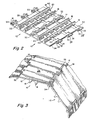
- Fig. 2 is a pictorial view of the bottom side of linked modules;
- Fig. 3 is a top pictorial view of linked modules;
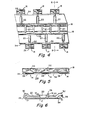
- Fig. 4 is a partial bottom view of a module;
- Fig. 5 is a partial end elevation view of a module;
- Fig. 6 is a sectional elevation view taken along lines 6-6 of Fig. 4;
- Fig. 7 is a top view of modules linked in brick-laid fashion;
- Fig. 8 is a a cutaway side elevation view illustrating linked modules in engagement with a sprocket wheel;
- Fig. 9 is an elevation view of a sprocket wheel employed with the linked modules; and
- Fig. 10 is a sectional end view of the sprocket wheel of Fig. 9.
- Referring to Figs. 1-6 of the drawing, there is shown a
module 10 which is interconnected with like modules to produce a modular linked conveyor belt in accordance with the invention. Eachmodule 10 is formed as an integral unitary structure of plastic material by well-known injection molding or other molding process. Each module includes a generally rectangular plate-like body 12 having a first pluralilty oflink ends 14 and a second plurality of longitudinally disposedribs 20 are spaced between thetransverse ribs 18. A plurality oflongitudinal ribs 22 also extend from eachtransverse rib 18 toward and terminate at the respective links 6. A pair oftranverse ribs 18 extend across the width of the body, and a plurality of longitudinal link ends. Thre grid structure formed by thetransverse ribs 18 and the interconnectinglongitudinal ribs structural portions 24 having upper surface portions (Fig. 3) coplanar with theupper conveyor surface 26 of thebody 12, and anend portion 28 which downwardly extends from the surface and which defines a partially cylindrical segment. For each link end, the partially cylindrical segments are aligned about a common transverse axis which is the pivot axis of adjacent interconnected links. Thelongitudinal ribs 22 which terminate at each link end include enclosedend portions 30 which circumscribe apivotal bore 31 therethrough which is in alignment with the pivot axis and through which apivot rod 32 extends to interconnect mated axis. Thepivot rods 32 are typically headed or otherwise deformed at their ends for axial retention in the module. - The
end portions 28 each include a partial interior cylindrical surface orbore 33 which has abearing surface 35 for thepivot rod 32 and which provides sufficient bearing surface area to accommodate the tensile forces produced by driving of the interconnected modules along a conveyor path under load. Theedges 34 of the module which confront thelink ends 28 of a mated module are bevelled to closely abut the rounded edges of thelink ends 28, and to provide only a small gap between mated links and maintain a substantially continuous conveying surface when mated links are disposed along a straight path, as seen in Fig. 1. Preferably, the modules are of link end configuration to be end-to-end reversible; that is, either end of a module can mate with either end of any link module. - Along a straight path, the mated modules each have an
upper conveying surface 26 which is substantially coplanar and continuous with that of adjacent links to provide effectively continuous and easily cleaned conveying surface with only a small parting line between adjacent modules. Thepivot rod 32 joining adjacent modules is covered by theend portions 28. Thepivot rod 32 is substantially exposed on the inner side of the links, as seen in Fig. 2, to provide visual access to the pivot rods and link ends for inspection and cleaning as required by industrial and governmental regulations, for example, in the food industry. The link ends and edges of each module are also exposed for ease of inspection when the belt is conveyed in a circular path around an associated sprocket, as shown in Figs. 3 and 8. - Confronting
inclined surfaces 40 of thetransverse ribs 18 define recesses which served as sprocket recesses located midway between the pivot axes of the module. These sprocket recesses are adapted to mate with correspondingsprocket teeth 42 of an associatedsprocket wheel 44, as shown in Figs. 1 and 8. Thesprocket wheel 44 is shown in Figs. 9 and 10 and hasteeth 42 withparallel side surfaces 46 and inclined front andback surfaces 48 configured to engage the corresponding surfaces of the sprocket recesses. Thesprocket wheel 44 has ahub 50 adapted to be secured to a square shaft. A sufficient plurality of sprocket wheels is employed across the width of the module to provide intended support and driving force, as shown in Fig. 1. The centrally driven sprocket recesses provide the benefits of minimizing chordal action and scrubbing between the mating surfaces of the module and the sprocket wheel. - The centrally disposed sprocket recesses can also be part of a module of different construction. The sprocket recesses can be considered as the inverse of center sprocket teeth. The placement of the sprocket recesses midway between the pivot axes, and the driving of the modules at this mid position, rather thasn driving the modules at the position of the pivot axes as is conventionally done, provide substantially constant speed drive of the conveyor belt, substantially eliminates sprocket-to-belt wear, and provides a belt capable of faster running speeds than conventional belts by reason of minimized chordal action and scrubbing. The confronting angled surfaces of the intermediate recesses also serves to present greater surface area to water and/or steam jets which can be located above and below the modules for cleaning of the belt. The angled sections also facilitate visual inspection of the belt.
- The modules are preferably made in widths which are multiples of the smallest module width so that modules can be arranged in brick-laid fashion to provide a conveyor belt of any desired overall width. Referring to Fig. 7, the illustrated belt is composed of modules 10a of a small width, and
modules 10b of a greater width which is triple the smaller width. The modules are staggered as shown such that laterally adjacent modules are straddled by a single module to achieve lateral interlocking of the belt. The modules may be easily cut to any intermediate widths such that belts of any width can be manufactured from a single standard part. - The modules are fabricated as an integral unitary structure by injection molding of a plastic material such as polyethylene. The particular material is determined in accordance with the characteristics desired to suit a particular operating environment. The pivot rods are typically of the same or compatible plastic material.
- The invention is not to be limited except as indicated in the appended claims.
Claims (12)
Priority Applications (2)
| Application Number | Priority Date | Filing Date | Title |
|---|---|---|---|
| EP19830112216 EP0144455B1 (en) | 1983-12-05 | 1983-12-05 | Flat top conveyor belt |
| DE8383112216T DE3375471D1 (en) | 1983-12-05 | 1983-12-05 | Flat top conveyor belt |
Applications Claiming Priority (1)
| Application Number | Priority Date | Filing Date | Title |
|---|---|---|---|
| EP19830112216 EP0144455B1 (en) | 1983-12-05 | 1983-12-05 | Flat top conveyor belt |
Publications (2)
| Publication Number | Publication Date |
|---|---|
| EP0144455A1 EP0144455A1 (en) | 1985-06-19 |
| EP0144455B1 true EP0144455B1 (en) | 1988-01-27 |
Family
ID=8190857
Family Applications (1)
| Application Number | Title | Priority Date | Filing Date |
|---|---|---|---|
| EP19830112216 Expired EP0144455B1 (en) | 1983-12-05 | 1983-12-05 | Flat top conveyor belt |
Country Status (2)
| Country | Link |
|---|---|
| EP (1) | EP0144455B1 (en) |
| DE (1) | DE3375471D1 (en) |
Cited By (2)
| Publication number | Priority date | Publication date | Assignee | Title |
|---|---|---|---|---|
| US6305530B1 (en) | 2000-05-30 | 2001-10-23 | Habasit Ag | Module for a modular conveying belt |
| DE102014118438A1 (en) * | 2014-12-11 | 2016-06-16 | Forbo Siegling Gmbh | Conveyor belt consisting of several modules and securing element for tool-free cutting of a coupling rod of the conveyor belt |
Families Citing this family (9)
| Publication number | Priority date | Publication date | Assignee | Title |
|---|---|---|---|---|
| US6725883B2 (en) | 2001-06-05 | 2004-04-27 | Habasit Ag | Flat top open hinge module |
| US20020195321A1 (en) * | 2001-06-20 | 2002-12-26 | Dieter Guldenfels | Flush Grid belt module |
| JP3513616B2 (en) * | 2001-06-28 | 2004-03-31 | 山久チヱイン株式会社 | Cross conveyor chain device |
| ES2283237B1 (en) * | 2007-04-23 | 2008-08-01 | Angel Carmelo San Miguel Zarzuela | LINK FOR CONVEYOR CHAINS AND CHAIN OBTAINED WITH THE SAME. |
| US8276747B2 (en) * | 2007-06-29 | 2012-10-02 | Habasit Ag | Module for a modular belt and a driving sprocket for easy cleaning |
| CN107150881B (en) * | 2016-03-02 | 2019-12-17 | 椿扬食品机械有限公司 | Anti-sticking conveyor belt and conveyor strip for frying machine |
| CN110341572A (en) * | 2019-02-03 | 2019-10-18 | 柳州旭龙汽车部件有限公司 | Conveyor belt dump truck compartment |
| DE102023102839A1 (en) * | 2023-02-06 | 2024-08-08 | TRUMPF Werkzeugmaschinen SE + Co. KG | Hinged conveyor belt for a conveyor system and laser cutting machine |
| CN116395320A (en) * | 2023-04-28 | 2023-07-07 | 上海永利带业股份有限公司 | A modular mesh belt and its matching sprockets |
Family Cites Families (6)
| Publication number | Priority date | Publication date | Assignee | Title |
|---|---|---|---|---|
| US2268542A (en) * | 1940-01-15 | 1942-01-06 | Charles M Clarke | Conveyer chain |
| US2708107A (en) * | 1952-11-10 | 1955-05-10 | Holcroft & Co | Work conveyor mechanism for heat treating furnaces |
| US2911091A (en) * | 1955-04-07 | 1959-11-03 | Chain Belt Co | Plastic flat top conveyer |
| US3870141A (en) * | 1970-08-13 | 1975-03-11 | Laitram Corp | Modular belt |
| US4159763A (en) * | 1977-08-02 | 1979-07-03 | The Laitram Corporation | Inspectable modular conveyor |
| IE50415B1 (en) * | 1980-01-15 | 1986-04-16 | Umec Boydell Belting Ltd | Conveyor belt of the honeycomb type |
-
1983
- 1983-12-05 EP EP19830112216 patent/EP0144455B1/en not_active Expired
- 1983-12-05 DE DE8383112216T patent/DE3375471D1/en not_active Expired
Cited By (3)
| Publication number | Priority date | Publication date | Assignee | Title |
|---|---|---|---|---|
| US6305530B1 (en) | 2000-05-30 | 2001-10-23 | Habasit Ag | Module for a modular conveying belt |
| DE102014118438A1 (en) * | 2014-12-11 | 2016-06-16 | Forbo Siegling Gmbh | Conveyor belt consisting of several modules and securing element for tool-free cutting of a coupling rod of the conveyor belt |
| DE102014118438B4 (en) * | 2014-12-11 | 2016-06-23 | Forbo Siegling Gmbh | Conveyor belt consisting of several modules and securing element for tool-free cutting of a coupling rod of the conveyor belt |
Also Published As
| Publication number | Publication date |
|---|---|
| DE3375471D1 (en) | 1988-03-03 |
| EP0144455A1 (en) | 1985-06-19 |
Similar Documents
| Publication | Publication Date | Title |
|---|---|---|
| US4688670A (en) | Flat top conveyor belt | |
| US4473365A (en) | Detachable link chain | |
| EP0113909B1 (en) | Lightweight modular conveyer belt | |
| US4231469A (en) | Conveyor | |
| CA2340294C (en) | Sprocket with combined hinge/center drive | |
| US4729469A (en) | Flat top conveyor belt | |
| US4832187A (en) | Modular center drive conveyor belt | |
| US4742907A (en) | Plastic conveyor belt | |
| US4815270A (en) | Detachable link chain | |
| US4882901A (en) | Detachable link chain | |
| KR100327962B1 (en) | Radial Conveyor Belts | |
| US5586643A (en) | Modular belting having antimicrobial characteristics and method of manufacture | |
| US4597747A (en) | Detachable link chain | |
| EP0144455A1 (en) | Flat top conveyor belt | |
| EP1184305B1 (en) | Modular plastic conveyor belt | |
| US4821872A (en) | Lightweight modular conveyor belt | |
| JP2010508221A (en) | Conveyor belt with rollers supported between modules | |
| US6305530B1 (en) | Module for a modular conveying belt | |
| CA2130653A1 (en) | Conveyor Belts with Spiral Overlay | |
| JP2711406B2 (en) | Module having drive connection and conveyor belt assembled from the module | |
| US4886158A (en) | Modular center drive conveyor belt | |
| CA1201407A (en) | Plastic conveyor belt | |
| EP0569103A1 (en) | Method for positioning dough pieces and device for performing thereof | |
| EP1799596B1 (en) | Belt module with oblong pivot hole | |
| CA2125544A1 (en) | Drive system for modular link conveyor belts |
Legal Events
| Date | Code | Title | Description |
|---|---|---|---|
| PUAI | Public reference made under article 153(3) epc to a published international application that has entered the european phase |
Free format text: ORIGINAL CODE: 0009012 |
|
| AK | Designated contracting states |
Designated state(s): DE FR GB IT |
|
| 17P | Request for examination filed |
Effective date: 19850729 |
|
| 17Q | First examination report despatched |
Effective date: 19860130 |
|
| D17Q | First examination report despatched (deleted) | ||
| GRAA | (expected) grant |
Free format text: ORIGINAL CODE: 0009210 |
|
| AK | Designated contracting states |
Kind code of ref document: B1 Designated state(s): DE FR GB IT |
|
| ITF | It: translation for a ep patent filed | ||
| REF | Corresponds to: |
Ref document number: 3375471 Country of ref document: DE Date of ref document: 19880303 |
|
| ET | Fr: translation filed | ||
| PLBE | No opposition filed within time limit |
Free format text: ORIGINAL CODE: 0009261 |
|
| STAA | Information on the status of an ep patent application or granted ep patent |
Free format text: STATUS: NO OPPOSITION FILED WITHIN TIME LIMIT |
|
| 26N | No opposition filed | ||
| ITTA | It: last paid annual fee | ||
| PGFP | Annual fee paid to national office [announced via postgrant information from national office to epo] |
Ref country code: GB Payment date: 19981110 Year of fee payment: 16 |
|
| PGFP | Annual fee paid to national office [announced via postgrant information from national office to epo] |
Ref country code: FR Payment date: 19981203 Year of fee payment: 16 |
|
| PGFP | Annual fee paid to national office [announced via postgrant information from national office to epo] |
Ref country code: DE Payment date: 19981230 Year of fee payment: 16 |
|
| PG25 | Lapsed in a contracting state [announced via postgrant information from national office to epo] |
Ref country code: GB Free format text: LAPSE BECAUSE OF NON-PAYMENT OF DUE FEES Effective date: 19991205 |
|
| GBPC | Gb: european patent ceased through non-payment of renewal fee |
Effective date: 19991205 |
|
| PG25 | Lapsed in a contracting state [announced via postgrant information from national office to epo] |
Ref country code: FR Free format text: LAPSE BECAUSE OF NON-PAYMENT OF DUE FEES Effective date: 20000831 |
|
| PG25 | Lapsed in a contracting state [announced via postgrant information from national office to epo] |
Ref country code: DE Free format text: LAPSE BECAUSE OF NON-PAYMENT OF DUE FEES Effective date: 20001003 |
|
| REG | Reference to a national code |
Ref country code: FR Ref legal event code: ST |