EP0144053A2 - Glare-shielding type reflector - Google Patents
Glare-shielding type reflector Download PDFInfo
- Publication number
- EP0144053A2 EP0144053A2 EP84114267A EP84114267A EP0144053A2 EP 0144053 A2 EP0144053 A2 EP 0144053A2 EP 84114267 A EP84114267 A EP 84114267A EP 84114267 A EP84114267 A EP 84114267A EP 0144053 A2 EP0144053 A2 EP 0144053A2
- Authority
- EP
- European Patent Office
- Prior art keywords
- glare
- shielding
- shielding layer
- reflector
- luminous flux
- Prior art date
- Legal status (The legal status is an assumption and is not a legal conclusion. Google has not performed a legal analysis and makes no representation as to the accuracy of the status listed.)
- Granted
Links
Images


Classifications
-
- B—PERFORMING OPERATIONS; TRANSPORTING
- B60—VEHICLES IN GENERAL
- B60R—VEHICLES, VEHICLE FITTINGS, OR VEHICLE PARTS, NOT OTHERWISE PROVIDED FOR
- B60R1/00—Optical viewing arrangements; Real-time viewing arrangements for drivers or passengers using optical image capturing systems, e.g. cameras or video systems specially adapted for use in or on vehicles
- B60R1/02—Rear-view mirror arrangements
- B60R1/08—Rear-view mirror arrangements involving special optical features, e.g. avoiding blind spots, e.g. convex mirrors; Side-by-side associations of rear-view and other mirrors
- B60R1/083—Anti-glare mirrors, e.g. "day-night" mirrors
- B60R1/088—Anti-glare mirrors, e.g. "day-night" mirrors using a cell of electrically changeable optical characteristic, e.g. liquid-crystal or electrochromic mirrors
-
- G—PHYSICS
- G02—OPTICS
- G02B—OPTICAL ELEMENTS, SYSTEMS OR APPARATUS
- G02B7/00—Mountings, adjusting means, or light-tight connections, for optical elements
- G02B7/18—Mountings, adjusting means, or light-tight connections, for optical elements for prisms; for mirrors
- G02B7/182—Mountings, adjusting means, or light-tight connections, for optical elements for prisms; for mirrors for mirrors
- G02B7/1822—Mountings, adjusting means, or light-tight connections, for optical elements for prisms; for mirrors for mirrors comprising means for aligning the optical axis
- G02B7/1827—Motorised alignment
-
- G—PHYSICS
- G02—OPTICS
- G02F—OPTICAL DEVICES OR ARRANGEMENTS FOR THE CONTROL OF LIGHT BY MODIFICATION OF THE OPTICAL PROPERTIES OF THE MEDIA OF THE ELEMENTS INVOLVED THEREIN; NON-LINEAR OPTICS; FREQUENCY-CHANGING OF LIGHT; OPTICAL LOGIC ELEMENTS; OPTICAL ANALOGUE/DIGITAL CONVERTERS
- G02F1/00—Devices or arrangements for the control of the intensity, colour, phase, polarisation or direction of light arriving from an independent light source, e.g. switching, gating or modulating; Non-linear optics
- G02F1/01—Devices or arrangements for the control of the intensity, colour, phase, polarisation or direction of light arriving from an independent light source, e.g. switching, gating or modulating; Non-linear optics for the control of the intensity, phase, polarisation or colour
- G02F1/15—Devices or arrangements for the control of the intensity, colour, phase, polarisation or direction of light arriving from an independent light source, e.g. switching, gating or modulating; Non-linear optics for the control of the intensity, phase, polarisation or colour based on an electrochromic effect
- G02F1/153—Constructional details
Definitions
- the present invention relates to a glare-shielding type reflector, more particularly to a reflector with a preventive mechanism against glaring by electrically controlling the reflectance thereof.
- the reflector of the present invention can be used as a room mirror for a vehicle, such as an automobile. It can protect a driver from being dazzled by the reflected beams of head lamps of a following car.
- the reflector of the present invention will be described as a room mirror for an automobile. However, the reflector of the present invention should not be restricted to a room mirror of an automobile.
- a glare-shielding type reflector for example, a reflector which is provided with a liquid crystal cell on a mirror surface has been conventionally known.
- a conventional glare-shielding type reflector reduces the light transmittance of the liquid crystal cell by controling an electric field applied thereto, and thus lessens the strength of the reflected beams.
- the application of an electric field, i.e., the driving of the liquid crystal cell is done by hand operation or automatic operation by use of a photosensor which detects the strength of the luminous flux (the beams).
- a driver feels dazzled by the beams reflected from only a part of the reflector surface and not from the entire surface.
- the driver is dazzled by the beams from the limited part of the reflector surface on which the image of the head lamps of a following car is projected.
- the conventional glare-shielding type reflector lessens the reflection from the entire reflector surface equally. Accordingly, the part of the reflector where the beams from the head lamps are reflected is controlled to provide a proper brightness, but the part of the reflector where the contour of a following car should be reflected becomes so dark that the contour is difficult to be recognized.
- the object of the present invention devised in due consideration of the above matter, is to provide a glare-shielding type reflector only the dazzling part of which is automatically prevented from glaring.
- the present invention provides a glare-shielding type reflector having a photosensor block which detects the incident angle of a luminous flux to the reflector and a glare-shielding layer which is divided into plural units and each unit of which is driven individually.
- the reflector of the present invention detects the incident angle of a luminous flux to the reflector by use of a photosensor block, decides the glare-shielding layer units to be driven according to the detected incident angle, and puts only the portion of the reflector corresponding to the glare-shielding layer units into a glare-shielding state by driving the glare-shielding layer units.
- the present invention is to put only the portion by which a driver feels dazzled into a glare-shielding state, while the reflectance of other portions, for example, where the contour of a following car should be reflected is not lowered, and therefore, the image of a reflected object can be readily perceived.
- a glare-shielding type reflector of the present invention the incident angle of a luminous flux incident to a reflector from the front side thereof, i.e., the mirror surface side thereof is detected, and a certain portion of the reflector surface by which a driver may feel dazzled is specified on the basis of the detected incident angle, and then the specified portion is turned to be glare-shielding.
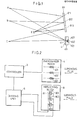
- Fig.l is an explanatory drawing for explaining the principle of the present invention.
- a beam emitted from Point A in the upper front of a reflector 81 is reflected at an upper portion 811 of the reflector, and then arrives at the eyes E of a driver.
- a beam emitted from Point C in the front is reflected at a lower portion 813 of the reflector, and then arrives at the eyes E of the driver. Therefore, when the headlight of a following car is located at A in Fig.l and is incident via the path shown in Fig.l, the driver may be satisfied if the glare-shielding state is maintained only in the upper portion 811 among the entire reflector surface 81.
- the incident angle of a luminous flux to the reflector can be detected by a photosensor block 4 which is shown in the bottom of Fig.l.
- a luminous flux emitted from A and incident onto a reflector along the path shown in Fig.l is detected by a photosensor 401, after its passage through a slit 41 and arrival at the photosensor 401.
- Photosensors 402 and 403 correspond to Points B and C in F1g.1, respectively.
- the positional relationships are also varied between the incident angle of a luminous flux to the reflector and each of the portions 811, 812 and 813 on the reflector 81, and similarly between each of the portions on the reflector 81 and photosensors 401, 402 and 403.
- the variation can be compensated by positional adjustment of the reflector and the like in accordance with the positions of the eyes E at an initial stage.
- the initial adjustment may be made by manual or electrical movement of a reflector with reference to, for example, a mark on the rear window of a car, or by suitable processing of initially input positional data.
- Fig.2 is a block diagram showing the scheme of the present invention.
- the glare-shielding type reflector of the present invention comprises;
- a reflecting block 8 has a mirror 81 and a glare-shielding layer 80 (801, 802 and 803).
- the mirror 81 has a shape of a plate and the function of reflecting and throwing back an incident light.
- This mirror 81 is produced by vapor deposition of a metal or a nonmetal, such as zinc sulfate (ZnS), cerium dioxide (CeO 2 ), titanium dioxide (Ti0 2 ), aluminum (Al), silver (Ag), chromium (Cr) or gold (Au) on the surface of a glass substrate, or the like.
- the glare-shielding layer 80 is formed on the mirror surface and has a function of varying the transmittance of the light through the layer 80, according to the average strength of an AC electric field applied to the layer 80 and thus controlling the intensity of the reflected lights.
- the glare-shielding layer is required to vary the light transmittance electrically.
- the glare-shielding layer can be formed by use of liquid crystal cells or electro- chromic cells.
- the liquid crystal cells used for this purpose include, for example; a Dynamic Scattering Mode (DSM) type liquid crystal cell which controls the light transmittance by dynamic scattering caused by application of an electric field thereto; a twist- nematic liquid crystal cell which controls the light transmittance by use of polarizers and an optical rotation effect of a nematic liquid crystal; a guest- host type liquid crystal cell which includes a liquid crystal mixed with a dichromatic pigment which absorbs a light polarized in a certain direction; a liquid crystal cell which provides the birefringence effect controlled by an electric field; and a liquid crystal cell which provides the phase transition effect between cholesteric and nematic phases.
- DSM Dynamic Scattering Mode
- Each of these liquid crystal cells generally intervenes between a pair of parallel transparent glass substrates, and on an inner surface of each glass substrate is installed a transparent electrode layer for applying an electric field to the intervening liquid crystal.
- the transparent electrode layer may be formed by use of indium stannous oxide (ITO), stannic oxide (SnO Z ), titanium dioxide (TiO 2 ), indium oxide (In 2 o 3 ) and the like.
- ITO indium stannous oxide
- SnO Z stannic oxide
- TiO 2 titanium dioxide
- In 2 o 3 indium oxide
- the glare-shielding layer 80 of the above construction is divided into plural glare-shielding layer units 801, 802,... which can be driven, on the mirror surface individually. In other words, the mirror surface is divided into plural divisions in accordance with the above-mentioned plural glare-shielding layer units.
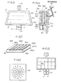
- the division may be done, for example, as illustrated in Fig.3 or Fig.8.
- the mirror surface 81 is divided into three horizontal strips 811, 812 and 813.
- the division is made by dividing the facing transparent electrodes 82a and 82b into mutually parallel strips 82al - 82a3 and 82bl - 82b3, respectively.
- the reflector is divided into a matrix.
- Fig.7 shows, such division is done by dividing each of the facing transparent electrodes into different series of strips 82al - 82a5 and 82bl - 82b3, which are orthogonal to each other.
- the driving unit 6 has a function of driving the glare-shielding layer 80 by application of an electric field thereto.
- the driving unit 6 is fed from an external source.
- a photosensor block 4 has a function of detecting the intensity and the incident angle of the luminous flux which is incident on the surface of the reflector from the front thereof.
- the photosensor block 4 has plural photosensors 401, 402,... each of which is designed to detect a luminous flux only when the incident angle of the flux to the surface becomes equal to a certain value which is predetermined for each photosensor.
- the detection of the incident angle may be achieved by arranging the photosensors 401, 402 and 403 in proper positions in the rear side of a slit 41 which functions as an aperture.
- a light emitted from Point A in the upper front of the reflector passes through the slit 41, and then reaches a photosensor 401 located at the bottom within a black box 49 in the photosensor block 4. Therefore, the luminous flux, which is emitted from Point A and passes along the path shown in Fig.l, can be detected by the photosensor 401.
- the photosensor block 4 shown in Fig.l detects the vertical variation of the incident angle of a luminous flux. As shown in Fig.8, the photosensor block 4 can also detect the horizontal variation of the incident angle by use of a vertical slit 412 for the slit 41.
- the slit shown in Fig.8 has a cruciform shape, the slit can detect both horizontal and vertical variations of the incident angle and any incident angle can be detected by suitable combination of these slits.
- a lens or a pinhole may be used as well as a slit.
- it is possible to detect any arbitrary incidental angle by arranging photosensors on concentric circles with the center on an optical axis of such aperture.
- a photosensor such a photoconductive cell as CdS or such a photogalvanic cell as photodiode may be used. These cells may be arrayed one- dimensionally or two-dimensionally to form a photosensor block.
- a photosensor block 4 may comprise a pinhole and an image sensor arrayed in the back of the pinhole.
- the controller 3 has functions to select the glare-shielding layer unit to be driven in accordance with a detected incident angle of a luminous flux to the surface, and to output the resulting informations to the driving unit 6 as control signals.
- the controller 3 selects the glare-shielding layer unit 801 to be driven (to prevent glaring on the upper portion 811 of the mirror 81 as shown in Fig.l).
- the glare-shielding reflector which has the above-mentioned construction can be applied to rearview mirrors of an automobile, such as room mirrors and side mirrors.
- Fig.3 is a front elevation of the reflector of the first embodiment of the present invention.
- Fig.4 is a cross-sectional view taken along the line IV - IV of Fig.3.
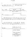
- Fig.5 is a diagram of the electric circuit showing the electrical element of the embodiment.
- Fig.6 is a timing chart explaining the operations of the circuit shown in Fig.5.
- the present embodiment denotes the case where liquid crystal cell is used as a glare-shielding layer and a mirror 81 is divided into three horizontal strip zones 811 - 813.
- the division of the mirror 81 is made by dividing the transparent electrode layers 82a and 82b into horizontal strip zones.
- the reflector of the present embodiment comprises a frame 91 which is attached to a car body (not shown) by the supporting member 92, the driving unit 6 and a controller 3 which are fixed within the frame 91, a reflecting block 8 attached to the inner periphery of the frame 91, and a photosensor block 4 attached to the lower portion of the- frame 91.
- the driving unit 6 is connected through electroconductive wires to a battery power source mounted on the car.
- the incidence of the luminous flux is detected by a photosensor 401 made of a CdS photoconductive cell. Namely, when the luminous flux is incident, the resistance of the photosensor 401 is lowered. Therefore, the voltage signal V401 which is got by dividing at the ratio of the resistances of the photosensor 401 and a resistance 4010 takes a higher level and is inputted to an AND-gate 31 of the controller 3.
- the other input terminal of the AND-gate 31 is connected to a resistance dividing point between a resistance 300 and a photoconductive cell 30.
- the photoconductive cell 30 is a photosensor which detects the brightness around the reflector, and disposed in the back of a sensor 4 as shown in Fig.4 not to be subject to the effect of the luminous flux.
- the voltage signal V30 which is varied in accordance with the relation of the resistance values of the resistance 300 and the photo conductive cell 30 takes a low level.
- the voltage signal V30 takes a high level.
- the output signal V31 of the AND-gate 31 takes a high level only when the reflector is in a dark environment and aizinous flux with a predetermined intensity is incident on the photosensor 401.
- the signal V31 is inputted to an Ex.OR- gate 61 in the driving unit 6.
- a signal V60 from an oscillating circuit 60 is inputted to the other terminal of the Ex.OR-gate 61.
- the output signal V61 from Ex ⁇ OR- gate 61 is applied to the transparent electrode 82bl of the glare-shielding layer unit 801.
- To the other transparent electrode 82al is applied the output signal V60 from the oscillating circuit 60. It is when the output signal V31 of the AND-gate 31 takes a high level that V60 (voltage applied to 82al) and V61 (voltage applied to 82bl) take opposite phases as shown in Fig.6 and the glare-shielding layer unit 801 is driven. This corresponds to the case where the photosensor 401 detects a luminous flux and a photoconductive cell 30 judges that the environment of the reflector is dark (nighttime).
- the glare-shielding layer unit 801 is driven and the upper portion of the mirror surface takes a glare-shielding state as shown in Fig.3.
- the photosensors 402 and 403 detect the flux, respectively and the center portion 812 or the lower portion 813 of the mirror takes a glare-shielding state.
- Fig.7 is a perspective fragmental view of the glare-shielding layer of the reflector according to the second embodiment.
- Fig.8 is an elevation view of the reflector of the second embodiment.
- the present embodiment corresponds to the case where the glare-shielding layer is divided into a matrix, and the division is made by dividing both of a pair of facing transparent electrodes into strips, and arranging the pair of transparent electrodes to be orthogonal to each other.
- the aperture 41 of the photosensor block 4 has a cross configuration of slits 411 and 412. The aim of this configuration is to detect not only the vertical variation of the incident angle of a luminous flux but also the horizontal variation thereof.
- the photosensors (not shown) are arranged vertically and horizontally in the back of the cross slits.
- Another type of photosensor block may comprise a pinhole and photosensors concentrically arranged in the back of the pinhole. Since the reflector of the second embodiment has the same construction of the mechanism as in the first embodiment except the glare-shielding layer and the photosensor block, the figure of the mechanism is not described here.
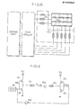
- Fig.10 is a block diagram of the electrical construction of the reflector of the second embodiment.
- Fig.ll is an electric circuit for explaining the block diagram of Fig.10.
- Fig.12 is a timing chart for explaining the operations of the circuit in Fig.ll.
- the photosensors 40i and 40j detect vertical and horizontal incident angle of a luminous flux to the reflector, respectively.
- the voltages Vi and Vj are applied to the glare-shielding layer unit 80ij (the unit on i-th row and j-th column), only when the photosensors 40i and 40j are in electrical conduction (are detecting a luminous flux).
- the applied voltages Vi and Vj are designed to have opposite phases by proper arrangement of field-effect transistors 35i, 36i, 35j and 36j, an inverter 600, and an oscillating circuit 60. Accordingly, only when both the photosensors 40i and 40j detect a luminous flux as shown in Fig.12, the glare-shielding layer unit 80ij is driven and the mirror surface unit 8lij takes a glare-shielding state. The same explanation can be applied to another glare-shielding layer units.
Abstract
Description
- The present invention relates to a glare-shielding type reflector, more particularly to a reflector with a preventive mechanism against glaring by electrically controlling the reflectance thereof.
- For instance, the reflector of the present invention can be used as a room mirror for a vehicle, such as an automobile. It can protect a driver from being dazzled by the reflected beams of head lamps of a following car.
- In the following specification, the reflector of the present invention will be described as a room mirror for an automobile. However, the reflector of the present invention should not be restricted to a room mirror of an automobile.
- As a glare-shielding type reflector, for example, a reflector which is provided with a liquid crystal cell on a mirror surface has been conventionally known. In case such strong beams from head lamps of a following car is incident on a reflector and a driver is dazzled by the reflection of the beams, a conventional glare-shielding type reflector reduces the light transmittance of the liquid crystal cell by controling an electric field applied thereto, and thus lessens the strength of the reflected beams. The application of an electric field, i.e., the driving of the liquid crystal cell, is done by hand operation or automatic operation by use of a photosensor which detects the strength of the luminous flux (the beams).
- However, even when the above-mentioned luminous flux is incident on the reflector, a driver feels dazzled by the beams reflected from only a part of the reflector surface and not from the entire surface. In other words, the driver is dazzled by the beams from the limited part of the reflector surface on which the image of the head lamps of a following car is projected.
- However, the conventional glare-shielding type reflector lessens the reflection from the entire reflector surface equally. Accordingly, the part of the reflector where the beams from the head lamps are reflected is controlled to provide a proper brightness, but the part of the reflector where the contour of a following car should be reflected becomes so dark that the contour is difficult to be recognized.
- The object of the present invention, devised in due consideration of the above matter, is to provide a glare-shielding type reflector only the dazzling part of which is automatically prevented from glaring.
- In short, the present invention provides a glare-shielding type reflector having a photosensor block which detects the incident angle of a luminous flux to the reflector and a glare-shielding layer which is divided into plural units and each unit of which is driven individually. As explained later in the preferred embodiments in detail, the reflector of the present invention detects the incident angle of a luminous flux to the reflector by use of a photosensor block, decides the glare-shielding layer units to be driven according to the detected incident angle, and puts only the portion of the reflector corresponding to the glare-shielding layer units into a glare-shielding state by driving the glare-shielding layer units. In other words, the present invention is to put only the portion by which a driver feels dazzled into a glare-shielding state, while the reflectance of other portions, for example, where the contour of a following car should be reflected is not lowered, and therefore, the image of a reflected object can be readily perceived.
-
- Fig.l is an explanatory view for the principle of the present invention.
- Fig.2 is a block diagram for showing a constitution of the present invention.
- Fig.3 is a front view of the reflector according to the first embodiment of the present invention.
- Fig.4 is a sectional view along line IV - IV of Fig.3.
- Fig.5 is an electric circuit diagram for showing an electrical constitution of the first embodiment of the present invention, and Fig.6 is a timing chart for explaining the operations of the circuit shown in Fig.5.
- Fig.7 is a perspective view of the glare.- shielding layer of the second embodiment of the present invention.
- Fig.8 is a front view of a reflector of the second embodiment.
- Fig.9 is an explanatory view of a photosensor block in which a pinhole is used as an aperture.
- Fig.10 is a block diagram of an electrical constitution of the second embodiment.
- Fig.ll is an electric circuit diagram for explaining the block diagram in Fig.10.
- Fig.12 is a timing chart for explaining the operations of the circuit shown in Fig.11.
- In a glare-shielding type reflector of the present invention, the incident angle of a luminous flux incident to a reflector from the front side thereof, i.e., the mirror surface side thereof is detected, and a certain portion of the reflector surface by which a driver may feel dazzled is specified on the basis of the detected incident angle, and then the specified portion is turned to be glare-shielding.
- Fig.l is an explanatory drawing for explaining the principle of the present invention.
- As shown in Fig.l, a beam emitted from Point A in the upper front of a
reflector 81 is reflected at anupper portion 811 of the reflector, and then arrives at the eyes E of a driver. On the other hand, a beam emitted from Point C in the front is reflected at alower portion 813 of the reflector, and then arrives at the eyes E of the driver. Therefore, when the headlight of a following car is located at A in Fig.l and is incident via the path shown in Fig.l, the driver may be satisfied if the glare-shielding state is maintained only in theupper portion 811 among theentire reflector surface 81. - The incident angle of a luminous flux to the reflector can be detected by a
photosensor block 4 which is shown in the bottom of Fig.l. A luminous flux emitted from A and incident onto a reflector along the path shown in Fig.l is detected by aphotosensor 401, after its passage through aslit 41 and arrival at thephotosensor 401. Namely, when thephotosensor 401 detects a luminous flux, the flux is regarded to have been incident on the reflector along the above-mentioned path.Photosensors - When the positions of driver's eyes E are varied, the positional relationships are also varied between the incident angle of a luminous flux to the reflector and each of the
portions reflector 81, and similarly between each of the portions on thereflector 81 andphotosensors - Fig.2 is a block diagram showing the scheme of the present invention.
- The glare-shielding type reflector of the present invention comprises;
- a reflecting
block 8 which further comprises amirror 81, and a glare-shielding layer 80 formed on the front surface of themirror 81, the light transmittance through which may be varied by application of an electric field; - a driving unit 6 which drives the glare-
shielding layer 80 by applying an electric field; - a
photosensor block 4 which detects the strength of a luminous flux which is incident on the reflectingblock 8 from the front of the reflectingblock 8; and - a controller 3 which outputs a control signal to the driving unit 6 for operating the glare-
shielding layer 80, when the strength of the luminous flux exceeds a prefixed value, - wherein, the glare-
shielding layer 80 further comprises plural glare-shielding layer units - the
photosensor block 4 detects the incident angle of the luminous flux incident to the reflectingblock 8, and - the controller 3 outputs a control signal for operating a specified glare-shielding layer unit which is decided by the incident angle of the luminous flux.
- A reflecting
block 8 has amirror 81 and a glare-shielding layer 80 (801, 802 and 803). Themirror 81 has a shape of a plate and the function of reflecting and throwing back an incident light. Thismirror 81 is produced by vapor deposition of a metal or a nonmetal, such as zinc sulfate (ZnS), cerium dioxide (CeO2), titanium dioxide (Ti02), aluminum (Al), silver (Ag), chromium (Cr) or gold (Au) on the surface of a glass substrate, or the like. The glare-shielding layer 80 is formed on the mirror surface and has a function of varying the transmittance of the light through thelayer 80, according to the average strength of an AC electric field applied to thelayer 80 and thus controlling the intensity of the reflected lights. The glare-shielding layer is required to vary the light transmittance electrically. For example, the glare-shielding layer can be formed by use of liquid crystal cells or electro- chromic cells. The liquid crystal cells used for this purpose include, for example; a Dynamic Scattering Mode (DSM) type liquid crystal cell which controls the light transmittance by dynamic scattering caused by application of an electric field thereto; a twist- nematic liquid crystal cell which controls the light transmittance by use of polarizers and an optical rotation effect of a nematic liquid crystal; a guest- host type liquid crystal cell which includes a liquid crystal mixed with a dichromatic pigment which absorbs a light polarized in a certain direction; a liquid crystal cell which provides the birefringence effect controlled by an electric field; and a liquid crystal cell which provides the phase transition effect between cholesteric and nematic phases. Each of these liquid crystal cells generally intervenes between a pair of parallel transparent glass substrates, and on an inner surface of each glass substrate is installed a transparent electrode layer for applying an electric field to the intervening liquid crystal. The transparent electrode layer may be formed by use of indium stannous oxide (ITO), stannic oxide (SnOZ), titanium dioxide (TiO2), indium oxide (In2o3) and the like. The glare-shielding layer 80 of the above construction is divided into plural glare-shielding layer units mirror surface 81 is divided into threehorizontal strips transparent electrodes - The driving unit 6 has a function of driving the glare-
shielding layer 80 by application of an electric field thereto. The driving unit 6 is fed from an external source. - A
photosensor block 4 has a function of detecting the intensity and the incident angle of the luminous flux which is incident on the surface of the reflector from the front thereof. For example, thephotosensor block 4 hasplural photosensors photosensors slit 41 which functions as an aperture. For instance, a light emitted from Point A in the upper front of the reflector passes through theslit 41, and then reaches a photosensor 401 located at the bottom within ablack box 49 in thephotosensor block 4. Therefore, the luminous flux, which is emitted from Point A and passes along the path shown in Fig.l, can be detected by thephotosensor 401. Thephotosensor block 4 shown in Fig.l detects the vertical variation of the incident angle of a luminous flux. As shown in Fig.8, thephotosensor block 4 can also detect the horizontal variation of the incident angle by use of avertical slit 412 for theslit 41. Besides, since the slit shown in Fig.8 has a cruciform shape, the slit can detect both horizontal and vertical variations of the incident angle and any incident angle can be detected by suitable combination of these slits. As a common aperture, a lens or a pinhole may be used as well as a slit. In the use of a lens or a pinhole, it is possible to detect any arbitrary incidental angle by arranging photosensors on concentric circles with the center on an optical axis of such aperture. As a photosensor, such a photoconductive cell as CdS or such a photogalvanic cell as photodiode may be used. These cells may be arrayed one- dimensionally or two-dimensionally to form a photosensor block. In addition, aphotosensor block 4 may comprise a pinhole and an image sensor arrayed in the back of the pinhole. - The controller 3 has functions to select the glare-shielding layer unit to be driven in accordance with a detected incident angle of a luminous flux to the surface, and to output the resulting informations to the driving unit 6 as control signals. As typically shown in Fig.2, when the
photosensor 401 detects a luminous flux, (which corresponds to the luminous flux in the path from Point A, as shown in Fig.l,) the controller 3 selects the glare-shielding layer unit 801 to be driven (to prevent glaring on theupper portion 811 of themirror 81 as shown in Fig.l). - The glare-shielding reflector which has the above-mentioned construction can be applied to rearview mirrors of an automobile, such as room mirrors and side mirrors.
- Detailed explanation will be made on preferred embodiments of the present invention.
- Fig.3 is a front elevation of the reflector of the first embodiment of the present invention. Fig.4 is a cross-sectional view taken along the line IV - IV of Fig.3. And Fig.5 is a diagram of the electric circuit showing the electrical element of the embodiment. Fig.6 is a timing chart explaining the operations of the circuit shown in Fig.5.
- As shown in Fig.3, the present embodiment denotes the case where liquid crystal cell is used as a glare-shielding layer and a
mirror 81 is divided into three horizontal strip zones 811 - 813. As Fig.4 shows, the division of themirror 81 is made by dividing thetransparent electrode layers frame 91 which is attached to a car body (not shown) by the supportingmember 92, the driving unit 6 and a controller 3 which are fixed within theframe 91, a reflectingblock 8 attached to the inner periphery of theframe 91, and aphotosensor block 4 attached to the lower portion of the-frame 91. And the driving unit 6 is connected through electroconductive wires to a battery power source mounted on the car. - The operations for glare shielding of the reflector will be explained as follows with reference to Figs.5 and 6, for the case where a luminous flux emitted from the upper front (Point A in Fig.l being supposed) is incident on the reflector Qf the present embodiment.
- The incidence of the luminous flux is detected by a
photosensor 401 made of a CdS photoconductive cell. Namely, when the luminous flux is incident, the resistance of thephotosensor 401 is lowered. Therefore, the voltage signal V401 which is got by dividing at the ratio of the resistances of thephotosensor 401 and aresistance 4010 takes a higher level and is inputted to an AND-gate 31 of the controller 3. The other input terminal of the AND-gate 31 is connected to a resistance dividing point between aresistance 300 and aphotoconductive cell 30. Thephotoconductive cell 30 is a photosensor which detects the brightness around the reflector, and disposed in the back of asensor 4 as shown in Fig.4 not to be subject to the effect of the luminous flux. When the reflector is in a bright environment (daytime), the voltage signal V30 which is varied in accordance with the relation of the resistance values of theresistance 300 and the photoconductive cell 30 takes a low level. On the other hand, when it is in dark (nighttime), the voltage signal V30 takes a high level. Accordingly, the output signal V31 of the AND-gate 31 takes a high level only when the reflector is in a dark environment and a luinous flux with a predetermined intensity is incident on thephotosensor 401. The signal V31 is inputted to an Ex.OR-gate 61 in the driving unit 6. And, a signal V60 from anoscillating circuit 60 is inputted to the other terminal of theEx.OR-gate 61. The output signal V61 from Ex·OR-gate 61 is applied to the transparent electrode 82bl of the glare-shielding layer unit 801. To the other transparent electrode 82al is applied the output signal V60 from theoscillating circuit 60. It is when the output signal V31 of the AND-gate 31 takes a high level that V60 (voltage applied to 82al) and V61 (voltage applied to 82bl) take opposite phases as shown in Fig.6 and the glare-shielding layer unit 801 is driven. This corresponds to the case where thephotosensor 401 detects a luminous flux and aphotoconductive cell 30 judges that the environment of the reflector is dark (nighttime). - Thus, when a luminous flux emitted from the upper front of the reflector is detected by the
photosensor 401, the glare-shielding layer unit 801 is driven and the upper portion of the mirror surface takes a glare-shielding state as shown in Fig.3. When a luminous flux is incident on the reflector from the horizontal front of the reflector (Point B in Fig.l) or the lower front of the reflector (Point C in Fig.l), thephotosensors center portion 812 or thelower portion 813 of the mirror takes a glare-shielding state. - Fig.7 is a perspective fragmental view of the glare-shielding layer of the reflector according to the second embodiment. Fig.8 is an elevation view of the reflector of the second embodiment.
- As shown in Figs.7 and 8, the present embodiment corresponds to the case where the glare-shielding layer is divided into a matrix, and the division is made by dividing both of a pair of facing transparent electrodes into strips, and arranging the pair of transparent electrodes to be orthogonal to each other. The
aperture 41 of thephotosensor block 4 has a cross configuration ofslits - Fig.10 is a block diagram of the electrical construction of the reflector of the second embodiment. Fig.ll is an electric circuit for explaining the block diagram of Fig.10. And Fig.12 is a timing chart for explaining the operations of the circuit in Fig.ll. The
photosensors 40i and 40j detect vertical and horizontal incident angle of a luminous flux to the reflector, respectively. As shown in Fig.11, the voltages Vi and Vj are applied to the glare-shielding layer unit 80ij (the unit on i-th row and j-th column), only when thephotosensors 40i and 40j are in electrical conduction (are detecting a luminous flux). The applied voltages Vi and Vj are designed to have opposite phases by proper arrangement of field-effect transistors 35i, 36i, 35j and 36j, aninverter 600, and anoscillating circuit 60. Accordingly, only when both thephotosensors 40i and 40j detect a luminous flux as shown in Fig.12, the glare-shielding layer unit 80ij is driven and the mirror surface unit 8lij takes a glare-shielding state. The same explanation can be applied to another glare-shielding layer units.
Claims (6)
both of said transparent electrode layers are divided into strips and one series of strip electrodes are arranged orthogonally to another series of strip electrodes.
said photosensor block has plural photosensors, each of which detects predetermined incident angle of said luminous flux, respectively.
said photosensors have a common aperture and are located at specified positions in the back of said aperture.
Applications Claiming Priority (2)
| Application Number | Priority Date | Filing Date | Title |
|---|---|---|---|
| JP225271/83 | 1983-11-29 | ||
| JP58225271A JPS60117218A (en) | 1983-11-29 | 1983-11-29 | Liquid crystal antidazzling type reflecting mirror |
Publications (3)
| Publication Number | Publication Date |
|---|---|
| EP0144053A2 true EP0144053A2 (en) | 1985-06-12 |
| EP0144053A3 EP0144053A3 (en) | 1987-08-26 |
| EP0144053B1 EP0144053B1 (en) | 1990-07-25 |
Family
ID=16826704
Family Applications (1)
| Application Number | Title | Priority Date | Filing Date |
|---|---|---|---|
| EP84114267A Expired EP0144053B1 (en) | 1983-11-29 | 1984-11-26 | Glare-shielding type reflector |
Country Status (4)
| Country | Link |
|---|---|
| US (1) | US4632509A (en) |
| EP (1) | EP0144053B1 (en) |
| JP (1) | JPS60117218A (en) |
| DE (1) | DE3482820D1 (en) |
Cited By (2)
| Publication number | Priority date | Publication date | Assignee | Title |
|---|---|---|---|---|
| GB2233468A (en) * | 1989-06-24 | 1991-01-09 | Martin Spence Wilson | Electronic reduction of glare |
| EP0555671A1 (en) * | 1992-02-10 | 1993-08-18 | Reliant Laser Corporation | Mirror with dazzle light attenuation zone |
Families Citing this family (65)
| Publication number | Priority date | Publication date | Assignee | Title |
|---|---|---|---|---|
| JPS60143301A (en) * | 1983-12-29 | 1985-07-29 | Nippon Denso Co Ltd | Nonglaring type reflection mirror and its manufacture |
| JPS60166651U (en) * | 1984-04-16 | 1985-11-05 | 市光工業株式会社 | Anti-glare mirror for vehicles |
| JPS60173431U (en) * | 1984-04-26 | 1985-11-16 | 株式会社東海理化電機製作所 | Automotive anti-glare mirror control device |
| JPS6159301A (en) * | 1984-08-30 | 1986-03-26 | Nippon Denso Co Ltd | Nonglaring type reflecting mirror controller |
| US4886328A (en) * | 1985-09-11 | 1989-12-12 | Yazaki Corporation | Display apparatus for vehicle with means to prevent solar heating thereof |
| KR880007296A (en) * | 1986-12-31 | 1988-08-26 | 한형수 | LCD rearview driving circuit |
| US5446576A (en) * | 1990-11-26 | 1995-08-29 | Donnelly Corporation | Electrochromic mirror for vehicles with illumination and heating control |
| DE4118208A1 (en) * | 1991-06-04 | 1991-11-07 | Veit Dr Thomas | Fast viewed displays control under variable lighting - uses light sensors for intensity, direction and spectrum and has liquid-crystal viewing panels |
| US5424898A (en) * | 1991-08-16 | 1995-06-13 | Donnelly Corporation | Fault tolerant drive circuit for electrochromic mirror system |
| US5193029A (en) * | 1991-11-19 | 1993-03-09 | Donnelly Corporation | Single sensor adaptive drive circuit for rearview mirror system |
| US5285060A (en) * | 1992-12-15 | 1994-02-08 | Donnelly Corporation | Display for automatic rearview mirror |
| US5877897A (en) | 1993-02-26 | 1999-03-02 | Donnelly Corporation | Automatic rearview mirror, vehicle lighting control and vehicle interior monitoring system using a photosensor array |
| US5670935A (en) | 1993-02-26 | 1997-09-23 | Donnelly Corporation | Rearview vision system for vehicle including panoramic view |
| US5550677A (en) * | 1993-02-26 | 1996-08-27 | Donnelly Corporation | Automatic rearview mirror system using a photosensor array |
| US6822563B2 (en) | 1997-09-22 | 2004-11-23 | Donnelly Corporation | Vehicle imaging system with accessory control |
| US7339149B1 (en) | 1993-02-26 | 2008-03-04 | Donnelly Corporation | Vehicle headlight control using imaging sensor |
| US5659423A (en) * | 1994-09-30 | 1997-08-19 | Donnelly Corporation | Modular variable reflectance mirror assembly |
| US6019475A (en) * | 1994-09-30 | 2000-02-01 | Donnelly Corporation | Modular rearview mirror assembly including an electronic control module |
| US6891563B2 (en) | 1996-05-22 | 2005-05-10 | Donnelly Corporation | Vehicular vision system |
| US7655894B2 (en) | 1996-03-25 | 2010-02-02 | Donnelly Corporation | Vehicular image sensing system |
| AU2628800A (en) | 1999-01-25 | 2000-08-07 | Gentex Corporation | Vehicle equipment control with semiconductor light sensors |
| US6402328B1 (en) * | 1999-01-25 | 2002-06-11 | Gentex Corporation | Automatic dimming mirror using semiconductor light sensor with integral charge collection |
| US6882287B2 (en) | 2001-07-31 | 2005-04-19 | Donnelly Corporation | Automotive lane change aid |
| US7697027B2 (en) | 2001-07-31 | 2010-04-13 | Donnelly Corporation | Vehicular video system |
| US7008090B2 (en) * | 2001-08-30 | 2006-03-07 | Donnelly Corporation | Vehicle mirror system with light conduiting member |
| US7038577B2 (en) | 2002-05-03 | 2006-05-02 | Donnelly Corporation | Object detection system for vehicle |
| TW557266B (en) * | 2002-11-21 | 2003-10-11 | Exon Science Inc | Outdoor vehicle and reflectivity control method of same |
| EP1442932A1 (en) * | 2003-01-23 | 2004-08-04 | Exon Science Inc. | Anti-glare rearview mirror assembly and reflectance control method of same |
| US7308341B2 (en) | 2003-10-14 | 2007-12-11 | Donnelly Corporation | Vehicle communication system |
| US7526103B2 (en) | 2004-04-15 | 2009-04-28 | Donnelly Corporation | Imaging system for vehicle |
| DE102004029876B4 (en) * | 2004-06-17 | 2009-01-29 | Deutsches Zentrum für Luft- und Raumfahrt e.V. | Exterior or rear view mirror for a motor vehicle |
| US7881496B2 (en) | 2004-09-30 | 2011-02-01 | Donnelly Corporation | Vision system for vehicle |
| US7720580B2 (en) | 2004-12-23 | 2010-05-18 | Donnelly Corporation | Object detection system for vehicle |
| WO2006106515A2 (en) * | 2005-04-05 | 2006-10-12 | Alphamirror Inc. | Automatic dimming liquid crystal mirror system |
| WO2007034469A1 (en) * | 2005-09-21 | 2007-03-29 | Alphamirror Inc. | Liquid crystal mirror adapted to filter light in the mesopic wavelength region |
| WO2008024639A2 (en) | 2006-08-11 | 2008-02-28 | Donnelly Corporation | Automatic headlamp control system |
| US8013780B2 (en) | 2007-01-25 | 2011-09-06 | Magna Electronics Inc. | Radar sensing system for vehicle |
| US7914187B2 (en) | 2007-07-12 | 2011-03-29 | Magna Electronics Inc. | Automatic lighting system with adaptive alignment function |
| US8017898B2 (en) | 2007-08-17 | 2011-09-13 | Magna Electronics Inc. | Vehicular imaging system in an automatic headlamp control system |
| US8451107B2 (en) | 2007-09-11 | 2013-05-28 | Magna Electronics, Inc. | Imaging system for vehicle |
| WO2009046268A1 (en) | 2007-10-04 | 2009-04-09 | Magna Electronics | Combined rgb and ir imaging sensor |
| US20100020170A1 (en) | 2008-07-24 | 2010-01-28 | Higgins-Luthman Michael J | Vehicle Imaging System |
| EP2401176B1 (en) | 2009-02-27 | 2019-05-08 | Magna Electronics | Alert system for vehicle |
| US9495876B2 (en) | 2009-07-27 | 2016-11-15 | Magna Electronics Inc. | Vehicular camera with on-board microcontroller |
| EP2459416B2 (en) | 2009-07-27 | 2019-12-25 | Magna Electronics Inc. | Parking assist system |
| EP2473871B1 (en) | 2009-09-01 | 2015-03-11 | Magna Mirrors Of America, Inc. | Imaging and display system for vehicle |
| US8890955B2 (en) | 2010-02-10 | 2014-11-18 | Magna Mirrors Of America, Inc. | Adaptable wireless vehicle vision system based on wireless communication error |
| US9117123B2 (en) | 2010-07-05 | 2015-08-25 | Magna Electronics Inc. | Vehicular rear view camera display system with lifecheck function |
| US9900522B2 (en) | 2010-12-01 | 2018-02-20 | Magna Electronics Inc. | System and method of establishing a multi-camera image using pixel remapping |
| US9264672B2 (en) | 2010-12-22 | 2016-02-16 | Magna Mirrors Of America, Inc. | Vision display system for vehicle |
| US9085261B2 (en) | 2011-01-26 | 2015-07-21 | Magna Electronics Inc. | Rear vision system with trailer angle detection |
| US8620523B2 (en) | 2011-06-24 | 2013-12-31 | Gentex Corporation | Rearview assembly with multiple ambient light sensors |
| US10793067B2 (en) | 2011-07-26 | 2020-10-06 | Magna Electronics Inc. | Imaging system for vehicle |
| US9224889B2 (en) | 2011-08-05 | 2015-12-29 | Gentex Corporation | Optical assembly for a light sensor, light sensor assembly using the optical assembly, and vehicle rearview assembly using the light sensor assembly |
| JP2015511329A (en) | 2012-01-31 | 2015-04-16 | アルファマイクロン インコーポレイテッド | Electronic dimmable optical device |
| EP2879912B1 (en) * | 2012-08-02 | 2021-11-10 | Gentex Corporation | System and method for controlling exterior vehicle lights responsive to detection of a semi-truck |
| US9446713B2 (en) | 2012-09-26 | 2016-09-20 | Magna Electronics Inc. | Trailer angle detection system |
| US9558409B2 (en) | 2012-09-26 | 2017-01-31 | Magna Electronics Inc. | Vehicle vision system with trailer angle detection |
| US9207116B2 (en) | 2013-02-12 | 2015-12-08 | Gentex Corporation | Light sensor |
| US9870753B2 (en) | 2013-02-12 | 2018-01-16 | Gentex Corporation | Light sensor having partially opaque optic |
| US10160382B2 (en) | 2014-02-04 | 2018-12-25 | Magna Electronics Inc. | Trailer backup assist system |
| KR102062840B1 (en) * | 2014-10-31 | 2020-02-11 | 삼성전자주식회사 | APPARATUS FOR DETECTING POSITION OF OBJECT using Binocular Parallax AND OPERATING METHOD THEREOF |
| US10875403B2 (en) | 2015-10-27 | 2020-12-29 | Magna Electronics Inc. | Vehicle vision system with enhanced night vision |
| US10132971B2 (en) | 2016-03-04 | 2018-11-20 | Magna Electronics Inc. | Vehicle camera with multiple spectral filters |
| EP3887204B1 (en) | 2018-11-26 | 2023-08-23 | Gentex Corporation | System for rearview camera as a glare sensor |
Citations (3)
| Publication number | Priority date | Publication date | Assignee | Title |
|---|---|---|---|---|
| FR2378295A1 (en) * | 1977-01-25 | 1978-08-18 | Fiat Spa | LIQUID CRYSTAL MIRROR, ESPECIALLY INTENDED TO BE USED AS A VEHICLE MIRROR. |
| GB2029343A (en) * | 1978-09-06 | 1980-03-19 | Rickson C | Mirrors with Control of Reflecting Power |
| GB2065046A (en) * | 1979-12-11 | 1981-06-24 | Cd Marketing Ltd | Wide angled rear view mirror apparatus |
Family Cites Families (41)
| Publication number | Priority date | Publication date | Assignee | Title |
|---|---|---|---|---|
| GB490516A (en) * | 1936-11-16 | 1938-08-16 | Ig Farbenindustrie Ag | Improved filters which absorb ultra-violet light |
| US2444976A (en) * | 1942-04-28 | 1948-07-13 | Libbey Owens Ford Glass Co | Absorption glasses |
| NL300132A (en) * | 1962-11-19 | |||
| US3600060A (en) * | 1968-02-23 | 1971-08-17 | Ncr Co | Display device containing minute droplets of cholesteric liquid crystals in a substantially continuous polymeric matrix |
| US3542455A (en) * | 1968-03-12 | 1970-11-24 | Ford Motor Co | Day-night outside rearview mirror assembly |
| US3986022A (en) * | 1973-06-04 | 1976-10-12 | Gilbert Peter Hyatt | Illumination control system |
| US3601614A (en) * | 1970-05-25 | 1971-08-24 | Chrysler Corp | Automatic anti-glare rearview mirror system |
| CH520937A (en) * | 1970-05-27 | 1972-03-31 | Bbc Brown Boveri & Cie | Arrangement for displaying an electrical measurement voltage by means of a display medium extending over a large area between two electrodes |
| FR2111683A1 (en) * | 1970-10-17 | 1972-06-09 | Degussa | Splinter proof mirror - of metal or plastic coated with reflecting metal covered with glass |
| GB1432382A (en) * | 1972-04-06 | 1976-04-14 | Matsushita Electric Ind Co Ltd | Method of driving a liquid crystal display device method of producing a drying filter |
| US3787110A (en) * | 1972-06-23 | 1974-01-22 | Bell Telephone Labor Inc | Liquid crystal devices |
| US3932026A (en) * | 1972-11-03 | 1976-01-13 | International Business Machines Corporation | Liquid crystal display assembly having dielectric coated electrodes |
| US3944331A (en) * | 1972-11-13 | 1976-03-16 | Ncr Corporation | Liquid crystal display device |
| JPS5444783B2 (en) * | 1973-01-11 | 1979-12-27 | ||
| US3862798A (en) * | 1973-11-19 | 1975-01-28 | Charles L Hopkins | Automatic rear view mirror adjuster |
| DE2416172A1 (en) * | 1974-04-03 | 1975-10-16 | Volkswagenwerk Ag | Anti-dazzle rear view mirror - with liquid crystal layer in mirror sandwich coupled to light detector |
| US3961181A (en) * | 1975-02-18 | 1976-06-01 | Golden Eddie R | Eye-shading means for automotive vehicle operators |
| DE2611339C3 (en) * | 1975-03-17 | 1979-02-08 | Sharp K.K., Osaka (Japan) | Mirror with information display |
| US3976875A (en) * | 1975-06-24 | 1976-08-24 | Rca Corporation | Photodetector filter structure |
| US4040727A (en) * | 1975-09-10 | 1977-08-09 | Rockwell International Corporation | Transflector |
| JPS5240348A (en) * | 1975-09-27 | 1977-03-29 | Nippon Kogaku Kk <Nikon> | Reflecting mirror formed of metallic film |
| DE2604462A1 (en) * | 1976-02-05 | 1977-08-11 | Siemens Ag | Antiglare rear view mirror for motor vehicles - has two support plates, liq. crystal layer, reflector and light sensitive cell |
| US4029393A (en) * | 1976-04-29 | 1977-06-14 | General Motors Corporation | Integrated thermally compensated liquid crystal display device |
| DE2732727A1 (en) * | 1976-08-24 | 1978-03-02 | Ford Werke Ag | Electronic dimming for driving mirror - has liq. crystal and polarising filters in front of mirror |
| US4201451A (en) * | 1976-09-03 | 1980-05-06 | Donald F. Hassinger | Wide angled rear view mirror apparatus |
| IT1117275B (en) * | 1977-02-25 | 1986-02-17 | Remo Bedini | AUTOMATIC METHOD AND DEVICE FOR THE ATTENTION OF THE DRIVING PHENOMENA IN REFLECTED LIGHT |
| US4095217A (en) * | 1977-03-07 | 1978-06-13 | Hirotsugu Tani | Combined liquid crystal display and photovoltaic converter |
| DE2726530C2 (en) * | 1977-06-13 | 1984-08-30 | D. Swarovski & Co., Wattens, Tirol | Concentrating solar panel |
| US4266859A (en) * | 1977-10-14 | 1981-05-12 | Citizen Watch Co., Ltd. | Liquid crystal display device |
| DE2808260A1 (en) * | 1978-02-25 | 1979-08-30 | Keck Klaus | Variable reflection effect driving mirror - has adjustable filter in front of mirror, with photocells to adjust transmission and set relative intensity of reflected light |
| JPS5539845A (en) * | 1978-09-12 | 1980-03-21 | Yoshitaka Ichikawa | Automobile mirror for confirming the rear |
| DE3061528D1 (en) * | 1979-03-13 | 1983-02-10 | Nat Res Dev | Analogue displays |
| US4279474A (en) * | 1980-03-25 | 1981-07-21 | Belgorod Barry M | Spectacle lens having continuously variable controlled density and fast response time |
| JPS574003A (en) * | 1980-06-11 | 1982-01-09 | Toshiba Electric Equip Corp | Solar energy absorber |
| JPS602650B2 (en) * | 1980-06-26 | 1985-01-23 | シャープ株式会社 | lcd cell |
| US4390874A (en) * | 1981-01-09 | 1983-06-28 | Texas Instruments Incorporated | Liquid crystal display system having improved temperature compensation |
| JPS57102603A (en) * | 1980-12-18 | 1982-06-25 | Seiko Epson Corp | Antiglare mirror |
| EP0088846B1 (en) * | 1982-03-05 | 1986-03-05 | Clearplas Limited | Mirror |
| US4491390A (en) * | 1982-05-06 | 1985-01-01 | Tong Shen Hsieh | Automatic liquid-crystal light shutter |
| JPS59111102A (en) * | 1982-12-16 | 1984-06-27 | Nippon Denso Co Ltd | Glare shielding type reflecting mirror |
| US4529278A (en) * | 1983-08-09 | 1985-07-16 | Nugent Robert T | Portable children's mirror |
-
1983
- 1983-11-29 JP JP58225271A patent/JPS60117218A/en active Pending
-
1984
- 1984-11-15 US US06/671,612 patent/US4632509A/en not_active Expired - Fee Related
- 1984-11-26 EP EP84114267A patent/EP0144053B1/en not_active Expired
- 1984-11-26 DE DE8484114267T patent/DE3482820D1/en not_active Expired - Lifetime
Patent Citations (3)
| Publication number | Priority date | Publication date | Assignee | Title |
|---|---|---|---|---|
| FR2378295A1 (en) * | 1977-01-25 | 1978-08-18 | Fiat Spa | LIQUID CRYSTAL MIRROR, ESPECIALLY INTENDED TO BE USED AS A VEHICLE MIRROR. |
| GB2029343A (en) * | 1978-09-06 | 1980-03-19 | Rickson C | Mirrors with Control of Reflecting Power |
| GB2065046A (en) * | 1979-12-11 | 1981-06-24 | Cd Marketing Ltd | Wide angled rear view mirror apparatus |
Cited By (2)
| Publication number | Priority date | Publication date | Assignee | Title |
|---|---|---|---|---|
| GB2233468A (en) * | 1989-06-24 | 1991-01-09 | Martin Spence Wilson | Electronic reduction of glare |
| EP0555671A1 (en) * | 1992-02-10 | 1993-08-18 | Reliant Laser Corporation | Mirror with dazzle light attenuation zone |
Also Published As
| Publication number | Publication date |
|---|---|
| EP0144053B1 (en) | 1990-07-25 |
| EP0144053A3 (en) | 1987-08-26 |
| DE3482820D1 (en) | 1990-08-30 |
| US4632509A (en) | 1986-12-30 |
| JPS60117218A (en) | 1985-06-24 |
Similar Documents
| Publication | Publication Date | Title |
|---|---|---|
| EP0144053B1 (en) | Glare-shielding type reflector | |
| EP0146672B1 (en) | Drive apparatus for a liquid crystal dazzle free mirror arrangement | |
| US5168378A (en) | Mirror with dazzle light attenuation zone | |
| US3961181A (en) | Eye-shading means for automotive vehicle operators | |
| US4690508A (en) | Liquid crystal closed-loop controlled mirror systems | |
| US8339526B2 (en) | Vehicle rearview mirror assembly including a high intensity display | |
| US6864927B1 (en) | Head up display with adjustable transparency screen | |
| US4669827A (en) | Detection of manipulation of position apparatus for dazzle-free mirror | |
| EP0111907B1 (en) | Non-glaring type reflector | |
| US20090027759A1 (en) | Electronic Window Shading System for Houses, Transport Vehicles and the Like | |
| JPS6159301A (en) | Nonglaring type reflecting mirror controller | |
| JPS60174342A (en) | Dazzlement preventing reflection mirror driving unit for vehicle | |
| US5691849A (en) | Rear-view assembly for a vehicle and an adaptor therefor | |
| EP0171766B1 (en) | Liquid crystal type dazzle-free reflection mirror | |
| US4696548A (en) | Antiglare mirror for an automobile | |
| CN211055041U (en) | Dimmable reflector, anti-glare rearview mirror and automobile | |
| JPH0425174B2 (en) | ||
| JPS622587Y2 (en) | ||
| CN214164705U (en) | Intelligent sun shield | |
| CN111746238B (en) | Automatic dimming sun shield with toilet mirror function | |
| JPH05203906A (en) | Antidazzling system | |
| JPS61246720A (en) | Antidazzle type reflecting mirror | |
| JPH0746910Y2 (en) | Driving circuit for ECD anti-glare mirror | |
| JPH0714344Y2 (en) | Light control glass structure with temperature control mechanism | |
| CN215971056U (en) | Automobile sun visor with light-adjustable LCD lens and automobile |
Legal Events
| Date | Code | Title | Description |
|---|---|---|---|
| PUAI | Public reference made under article 153(3) epc to a published international application that has entered the european phase |
Free format text: ORIGINAL CODE: 0009012 |
|
| AK | Designated contracting states |
Designated state(s): DE FR GB |
|
| PUAL | Search report despatched |
Free format text: ORIGINAL CODE: 0009013 |
|
| AK | Designated contracting states |
Kind code of ref document: A3 Designated state(s): DE FR GB |
|
| 17P | Request for examination filed |
Effective date: 19871008 |
|
| 17Q | First examination report despatched |
Effective date: 19891206 |
|
| GRAA | (expected) grant |
Free format text: ORIGINAL CODE: 0009210 |
|
| AK | Designated contracting states |
Kind code of ref document: B1 Designated state(s): DE FR GB |
|
| ET | Fr: translation filed | ||
| REF | Corresponds to: |
Ref document number: 3482820 Country of ref document: DE Date of ref document: 19900830 |
|
| PLBE | No opposition filed within time limit |
Free format text: ORIGINAL CODE: 0009261 |
|
| STAA | Information on the status of an ep patent application or granted ep patent |
Free format text: STATUS: NO OPPOSITION FILED WITHIN TIME LIMIT |
|
| 26N | No opposition filed | ||
| PGFP | Annual fee paid to national office [announced via postgrant information from national office to epo] |
Ref country code: FR Payment date: 19981110 Year of fee payment: 15 |
|
| PGFP | Annual fee paid to national office [announced via postgrant information from national office to epo] |
Ref country code: GB Payment date: 19981127 Year of fee payment: 15 |
|
| PGFP | Annual fee paid to national office [announced via postgrant information from national office to epo] |
Ref country code: DE Payment date: 19981207 Year of fee payment: 15 |
|
| PG25 | Lapsed in a contracting state [announced via postgrant information from national office to epo] |
Ref country code: GB Free format text: LAPSE BECAUSE OF NON-PAYMENT OF DUE FEES Effective date: 19991126 |
|
| GBPC | Gb: european patent ceased through non-payment of renewal fee |
Effective date: 19991126 |
|
| PG25 | Lapsed in a contracting state [announced via postgrant information from national office to epo] |
Ref country code: FR Free format text: LAPSE BECAUSE OF NON-PAYMENT OF DUE FEES Effective date: 20000731 |
|
| PG25 | Lapsed in a contracting state [announced via postgrant information from national office to epo] |
Ref country code: DE Free format text: LAPSE BECAUSE OF NON-PAYMENT OF DUE FEES Effective date: 20000901 |
|
| REG | Reference to a national code |
Ref country code: FR Ref legal event code: ST |