EP0143616A2 - Hybrid circuit - Google Patents
Hybrid circuit Download PDFInfo
- Publication number
- EP0143616A2 EP0143616A2 EP84308112A EP84308112A EP0143616A2 EP 0143616 A2 EP0143616 A2 EP 0143616A2 EP 84308112 A EP84308112 A EP 84308112A EP 84308112 A EP84308112 A EP 84308112A EP 0143616 A2 EP0143616 A2 EP 0143616A2
- Authority
- EP
- European Patent Office
- Prior art keywords
- hybrid circuit
- secondary winding
- input
- amplifier
- signal
- Prior art date
- Legal status (The legal status is an assumption and is not a legal conclusion. Google has not performed a legal analysis and makes no representation as to the accuracy of the status listed.)
- Ceased
Links
Images

Classifications
-
- H—ELECTRICITY
- H04—ELECTRIC COMMUNICATION TECHNIQUE
- H04B—TRANSMISSION
- H04B1/00—Details of transmission systems, not covered by a single one of groups H04B3/00 - H04B13/00; Details of transmission systems not characterised by the medium used for transmission
- H04B1/38—Transceivers, i.e. devices in which transmitter and receiver form a structural unit and in which at least one part is used for functions of transmitting and receiving
- H04B1/40—Circuits
- H04B1/54—Circuits using the same frequency for two directions of communication
- H04B1/58—Hybrid arrangements, i.e. arrangements for transition from single-path two-direction transmission to single-direction transmission on each of two paths or vice versa
- H04B1/581—Hybrid arrangements, i.e. arrangements for transition from single-path two-direction transmission to single-direction transmission on each of two paths or vice versa using a transformer
Definitions
- This invention relates generally to hybrid circuits, and more particularly to a hybrid circuit for interfacing a two-wire line and a four-wire line.
- the four-wire line comprises two wires that provide a receive path for signals and two wires that provide a transmit path for signals.
- the two-wire line provides both a receive path and a transmit path on a common pair of wires.
- the two-wire line extends from a subscriber's telephone set to a switching office. At the switching office it is common to convert the two-wire bidirectional line to the four-wire (two unidirectional paths) line by use of a hybrid circuit.
- Hybrid circuits are well known and the following patents describe but a few of the known techniques in this field: United States patent 2,946,861 dated July 26, 1960 by Li-Yen Chen; United States patent 4,232,293 by H.H. Harris dated November 4, 1980; United States patent 4,322,586 dated March 30, 1982 by G.F. Mein and J.B. Terry; United States patent 4,346,266 dated August 24, 1982 by Brockmann et al; and United States patent No. 4,346,267 dated August 24, 1982 by E.C. Dijkmans. Attention is respectfully directed to the above listed patents.
- Desired objects for a hybrid circuit of this type are to maximize the return loss and to increase the efficiency of the hybrid circuit. Previously this has been accomplished by the use of two R-C (resistor-capacitor) networks on the four-wire side (note: this is depicted in more detail in Figure 1). Another object is to maximize the transhybrid loss.
- the present invention is directed to increasing the efficiency of a hybrid circuit while maintaining relatively high return loss and relatively high transhybrid loss. In simplistic terms, this is achieved by eliminating one of the R-C networks of the prior art hybrid circuit referred to above, and replacing it with an operational amplifier.
- the present invention is a hybrid circuit for interfacing a two-wire bidirectional line and a pair of two-wire unidirectional lines, the hybrid circuit comprising: a transformer having two primary windings and a center tapped secondary winding; the primary windings being interconnected in a voltage aiding serial relationship, by a capacitance means; an operational amplifier having a first input responsive to the signal on a first one of the unidirectional lines, having its second input responsive to the signal on the center tap of the secondary winding, and having its output applied to a first end of the secondary winding; and the second one of the unidirectional lines being responsive to the signal on the second end of the secondary winding.
- Transformer 18 has split primary windings 19a and 19b and a secondary winding 21 comprised of two equal sections 21a and 21b with a center tap connection at 22.
- a battery 23 is depicted connected to the primary windings 19a and 19b via feed resistors 26 and 27 for supplying DC power to equipment connected to the subscriber's loop (e.g. a telephone set).
- Capacitor 28 connects windings 19a and 19b in a series circuit relationship so as to allow the passage of AC signals while blocking the flow of DC current.
- Signals from a switching office are received on wires 13 and 14.
- the signal on wire 13 is applied to amplifier 31, thence to the series combination of resistor 32 and capacitor 33 and to one end of winding 21b.
- Signals destined for the switching office are applied to wires 15 and 16. These signals are taken from one end of winding 21a (as depicted in Figure 1) and are applied via capacitor 34 to wire 15. Resistor 36 between wire 15 and ground is the termination of the transmit port of hybrid 10 and resistor 37 is the balancing resistor.
- the signal received on wires 13 and 14 experiences loss due to capacitor 33 and resistor 32.
- the signal transmitted to the switching office (not shown) on wires 15 and 16 experiences loss due to capacitor 34 and resistor 36.
- FIG 2 depicts a simplified schematic of the preferred embodiment of hybrid circuit 38 constructed according to the present invention.
- the components on the subscriber's loop side of hybrid 38 i.e. wires 11 and 12, transformer 18, resistors 26 and 27, capacitor 28, and battery 23) are the same as in Figure 1.
- wire 13 is applied to the non-inverting input of operational amplifier 39 (e.g. an NE 5532).
- the output of amplifier 39 is applied to one end of winding 21b as shown, and the other end of winding 21b (i.e. center tap connection 22) is applied to the inverting input of amplifier 39.
- Amplifier 39 is operated in a feedback configuration and has a gain of approximately two.
- Resistor 37 is connected between center tap connection 22 and ground 41.
- the end of winding 21a, remote from tap 22, is connected to wire 15 via capacitor 34, and resistor 36 connects wire 15 to ground 41.
- signals received on windings 19a and 19b, from tip wire 12 and ring wire 11 are applied to transmit wires 15 and 16 (i.e. transmit port 29); and signals received on wires 13 and 14 (i.e. receive port 30) are applied to tip wire 12 and ring wire 11.
- a comparison of hybrid circuit 38 of Figure 2 and hybrid circuit 10 of Figure 1 shows that the resistor 32 and capacitor 33 (both of Figure 1) that are in the receive path have been eliminated in hybrid circuit 38 of Figure 2; consequently, the signal loss associated with these two components has also been eliminated in the Figure 2 embodiment.
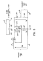
- Figure 3 is the same as Figure 2 except that it is further simplified and has been oriented differently to facilitate the description of its operation. It is believed that the circuit of Figure 3 (and consequently the circuit of Figure 2) functions as follows.
- the R-C termination (i.e. resistor 36 and capacitor 34) on transmit port 29 is automatically matched on the receive port 30 by forcing the signal on tap 22 to approximately zero.
- the circuit of Figure 3 is transmitting only (i.e. a signal is received from tip 12 and ring 11 and applied to wires 15 and 16) then the voltages are as follows:
- resistor 37 srould have a value approximately equal to 1/4 of the reflected primary load as seen across the ends of secondary winding 21.
- resistor 37 should be 1/4 (900 + 42.5) (1.0495) 2 which is 259.529 and is approximated by resistor 37 being 261 ohms (note: frequency is 200 Hertz to 3400 Hertz).
Abstract
Description
- This invention relates generally to hybrid circuits, and more particularly to a hybrid circuit for interfacing a two-wire line and a four-wire line.
- In telephone systems and the like it is often necessary to couple a four-wire line to a two-wire line. More specifically, the four-wire line comprises two wires that provide a receive path for signals and two wires that provide a transmit path for signals. The two-wire line provides both a receive path and a transmit path on a common pair of wires. Most frequently, the two-wire line extends from a subscriber's telephone set to a switching office. At the switching office it is common to convert the two-wire bidirectional line to the four-wire (two unidirectional paths) line by use of a hybrid circuit.
- Hybrid circuits are well known and the following patents describe but a few of the known techniques in this field: United States patent 2,946,861 dated July 26, 1960 by Li-Yen Chen; United States patent 4,232,293 by H.H. Harris dated November 4, 1980; United States patent 4,322,586 dated March 30, 1982 by G.F. Mein and J.B. Terry; United States patent 4,346,266 dated August 24, 1982 by Brockmann et al; and United States patent No. 4,346,267 dated August 24, 1982 by E.C. Dijkmans. Attention is respectfully directed to the above listed patents.
- Desired objects for a hybrid circuit of this type are to maximize the return loss and to increase the efficiency of the hybrid circuit. Previously this has been accomplished by the use of two R-C (resistor-capacitor) networks on the four-wire side (note: this is depicted in more detail in Figure 1). Another object is to maximize the transhybrid loss.
- The present invention is directed to increasing the efficiency of a hybrid circuit while maintaining relatively high return loss and relatively high transhybrid loss. In simplistic terms, this is achieved by eliminating one of the R-C networks of the prior art hybrid circuit referred to above, and replacing it with an operational amplifier.
- Stated in other terms, the present invention is a hybrid circuit for interfacing a two-wire bidirectional line and a pair of two-wire unidirectional lines, the hybrid circuit comprising: a transformer having two primary windings and a center tapped secondary winding; the primary windings being interconnected in a voltage aiding serial relationship, by a capacitance means; an operational amplifier having a first input responsive to the signal on a first one of the unidirectional lines, having its second input responsive to the signal on the center tap of the secondary winding, and having its output applied to a first end of the secondary winding; and the second one of the unidirectional lines being responsive to the signal on the second end of the secondary winding.
- The invention will now be described in more detail with reference to the accompanying drawings, wherein like parts in each of the several figures are identified by the same reference character, and wherein:
- Figure 1 is a simplified schematic of a prior art hybrid circuit;
- Figure 2 is a simplified schematic of the preferred embodiment of the hybrid circuit of the present invention; and
- Figure 3 is a further simplification of, and re-orientation of, the Figure 2 circuit.
- Figure 1 depicts a simplified prior
art hybrid circuit 10 used for interfacingTIP wire 12 and RING wire 11 of a subscriber's loop both towires wires 16 and 17 forming a two-wire transmit line. - Transformer 18 has split
primary windings secondary winding 21 comprised of twoequal sections - A
battery 23 is depicted connected to theprimary windings feed resistors windings - Signals from a switching office (not shown) are received on
wires wire 13 is applied toamplifier 31, thence to the series combination ofresistor 32 andcapacitor 33 and to one end of winding 21b. - Signals destined for the switching office (not shown) are applied to
wires capacitor 34 towire 15.Resistor 36 betweenwire 15 and ground is the termination of the transmit port ofhybrid 10 andresistor 37 is the balancing resistor. - As is apparent from the Figure 1 embodiment, the signal received on
wires capacitor 33 andresistor 32. Similarly, the signal transmitted to the switching office (not shown) onwires capacitor 34 andresistor 36. - Figure 2 depicts a simplified schematic of the preferred embodiment of
hybrid circuit 38 constructed according to the present invention. The components on the subscriber's loop side of hybrid 38 (i.e. wires 11 and 12,transformer 18,resistors capacitor 28, and battery 23) are the same as in Figure 1. - On the switching office side of
hybrid 38,wire 13 is applied to the non-inverting input of operational amplifier 39 (e.g. an NE 5532). The output ofamplifier 39 is applied to one end of winding 21b as shown, and the other end of winding 21b (i.e. center tap connection 22) is applied to the inverting input ofamplifier 39.Amplifier 39 is operated in a feedback configuration and has a gain of approximately two.Resistor 37 is connected betweencenter tap connection 22 andground 41. The end of winding 21a, remote fromtap 22, is connected towire 15 viacapacitor 34, andresistor 36 connectswire 15 toground 41. - Consequently, signals received on
windings tip wire 12 and ring wire 11 (i.e. bidirectional port 24) are applied to transmitwires 15 and 16 (i.e. transmit port 29); and signals received onwires 13 and 14 (i.e. receive port 30) are applied totip wire 12 and ring wire 11. - A comparison of
hybrid circuit 38 of Figure 2 andhybrid circuit 10 of Figure 1 shows that theresistor 32 and capacitor 33 (both of Figure 1) that are in the receive path have been eliminated inhybrid circuit 38 of Figure 2; consequently, the signal loss associated with these two components has also been eliminated in the Figure 2 embodiment. - Figure 3 is the same as Figure 2 except that it is further simplified and has been oriented differently to facilitate the description of its operation. It is believed that the circuit of Figure 3 (and consequently the circuit of Figure 2) functions as follows.
- The R-C termination (
i.e. resistor 36 and capacitor 34) on transmitport 29 is automatically matched on thereceive port 30 by forcing the signal ontap 22 to approximately zero. When the circuit of Figure 3 is transmitting only (i.e. a signal is received fromtip 12 and ring 11 and applied towires 15 and 16) then the voltages are as follows:

- When the circuit of Figure 3 is receiving a signal on
wires 

- Note that the proper operation requires the appropriate value for
resistor 37. It is believed thatresistor 37 srould have a value approximately equal to 1/4 of the reflected primary load as seen across the ends ofsecondary winding 21. In other words, for a load of 900 ohms in series with 2.15 microfarads connected acrosstip wire 12 and ring wire 11, and a transformer turns ratio of 1:1.0495, the value ofresistor 37 should be 1/4 (900 + 42.5) (1.0495)2 which is 259.529 and is approximated byresistor 37 being 261 ohms (note: frequency is 200 Hertz to 3400 Hertz).
Claims (5)
Applications Claiming Priority (2)
| Application Number | Priority Date | Filing Date | Title |
|---|---|---|---|
| US06/555,971 US4595802A (en) | 1983-11-29 | 1983-11-29 | Hybrid circuit |
| US555971 | 1983-11-29 |
Publications (2)
| Publication Number | Publication Date |
|---|---|
| EP0143616A2 true EP0143616A2 (en) | 1985-06-05 |
| EP0143616A3 EP0143616A3 (en) | 1986-06-04 |
Family
ID=24219368
Family Applications (1)
| Application Number | Title | Priority Date | Filing Date |
|---|---|---|---|
| EP84308112A Ceased EP0143616A3 (en) | 1983-11-29 | 1984-11-22 | Hybrid circuit |
Country Status (4)
| Country | Link |
|---|---|
| US (1) | US4595802A (en) |
| EP (1) | EP0143616A3 (en) |
| JP (1) | JPS60137139A (en) |
| CA (1) | CA1202382A (en) |
Cited By (3)
| Publication number | Priority date | Publication date | Assignee | Title |
|---|---|---|---|---|
| EP0399408A2 (en) * | 1989-05-23 | 1990-11-28 | Hoechst Aktiengesellschaft | Apparatus for facsimile transmission |
| AU653659B2 (en) * | 1991-12-20 | 1994-10-06 | Ke Kommunikations-Elektronik Gmbh & Co | A branching circuit |
| EP0682435A2 (en) * | 1990-09-04 | 1995-11-15 | RAYCHEM CORPORATION (a Delaware corporation) | Alarm and test system with improved coupling circuit for a digital added main line |
Families Citing this family (5)
| Publication number | Priority date | Publication date | Assignee | Title |
|---|---|---|---|---|
| US4783921A (en) * | 1987-06-22 | 1988-11-15 | Stout Industries, Inc. | Mounting arrangement for wind-deflectable bending sign |
| US5274704A (en) * | 1989-01-19 | 1993-12-28 | Northern Telecom Limited | Transformer telephone line interface circuit |
| US4982426A (en) * | 1989-01-19 | 1991-01-01 | Northern Telecom Limited | Telecommunications line interface circuits |
| WO1993009612A1 (en) * | 1991-10-30 | 1993-05-13 | Raychem Corporation | Alarm and test system with improved coupling circuit for a digital added main line |
| US7054279B2 (en) * | 2000-04-07 | 2006-05-30 | Broadcom Corporation | Method and apparatus for optimizing signal transformation in a frame-based communications network |
Citations (3)
| Publication number | Priority date | Publication date | Assignee | Title |
|---|---|---|---|---|
| US3818140A (en) * | 1972-11-17 | 1974-06-18 | Bendix Corp | Telephone line receiver and transmitter |
| DE2952259A1 (en) * | 1978-12-30 | 1980-07-17 | Plessey Handel Investment Ag | TWO-WIRE-FOUR-WIRE COMMUNICATION CIRCUIT |
| FR2456430A1 (en) * | 1979-05-11 | 1980-12-05 | Philips Nv | FOUR-WIRE CIRCUIT TERMINAL |
Family Cites Families (9)
| Publication number | Priority date | Publication date | Assignee | Title |
|---|---|---|---|---|
| US2946861A (en) * | 1955-04-29 | 1960-07-26 | Directorate General Of Telecom | Vacuum tube hybrid |
| US3130274A (en) * | 1960-10-20 | 1964-04-21 | Itt | 2-or 4-wire telephone set |
| US4197431A (en) * | 1978-10-02 | 1980-04-08 | Digital Telephone Systems, Inc. | Subscriber loop feed apparatus |
| DE2911866C3 (en) * | 1979-03-26 | 1982-03-11 | Siemens AG, 1000 Berlin und 8000 München | Arrangement with a hybrid circuit for the two-wire to four-wire transition in PCM time division multiplex systems |
| NL7903797A (en) * | 1979-05-15 | 1980-11-18 | Philips Nv | FORK SHIFT. |
| CA1123102A (en) * | 1979-07-27 | 1982-05-04 | Harold H. Harris | Line interface unit for voice and wide band signal coupling |
| US4322586A (en) * | 1980-11-13 | 1982-03-30 | Northern Telecom Limited | Transformerless line interface circuit |
| JPS57104336A (en) * | 1980-12-20 | 1982-06-29 | Oki Electric Ind Co Ltd | Hybrid circuit |
| JPS60122582A (en) * | 1983-07-27 | 1985-07-01 | マルマンゴルフ株式会社 | Production of grip for golf club |
-
1983
- 1983-11-29 US US06/555,971 patent/US4595802A/en not_active Expired - Lifetime
-
1984
- 1984-03-14 CA CA000449580A patent/CA1202382A/en not_active Expired
- 1984-11-22 EP EP84308112A patent/EP0143616A3/en not_active Ceased
- 1984-11-28 JP JP59249810A patent/JPS60137139A/en active Pending
Patent Citations (3)
| Publication number | Priority date | Publication date | Assignee | Title |
|---|---|---|---|---|
| US3818140A (en) * | 1972-11-17 | 1974-06-18 | Bendix Corp | Telephone line receiver and transmitter |
| DE2952259A1 (en) * | 1978-12-30 | 1980-07-17 | Plessey Handel Investment Ag | TWO-WIRE-FOUR-WIRE COMMUNICATION CIRCUIT |
| FR2456430A1 (en) * | 1979-05-11 | 1980-12-05 | Philips Nv | FOUR-WIRE CIRCUIT TERMINAL |
Cited By (5)
| Publication number | Priority date | Publication date | Assignee | Title |
|---|---|---|---|---|
| EP0399408A2 (en) * | 1989-05-23 | 1990-11-28 | Hoechst Aktiengesellschaft | Apparatus for facsimile transmission |
| EP0399408A3 (en) * | 1989-05-23 | 1992-03-04 | Hoechst Aktiengesellschaft | Apparatus for facsimile transmission |
| EP0682435A2 (en) * | 1990-09-04 | 1995-11-15 | RAYCHEM CORPORATION (a Delaware corporation) | Alarm and test system with improved coupling circuit for a digital added main line |
| EP0682435A3 (en) * | 1990-09-04 | 1996-07-17 | Raychem Corp | Alarm and test system with improved coupling circuit for a digital added main line. |
| AU653659B2 (en) * | 1991-12-20 | 1994-10-06 | Ke Kommunikations-Elektronik Gmbh & Co | A branching circuit |
Also Published As
| Publication number | Publication date |
|---|---|
| CA1202382A (en) | 1986-03-25 |
| US4595802A (en) | 1986-06-17 |
| JPS60137139A (en) | 1985-07-20 |
| EP0143616A3 (en) | 1986-06-04 |
Similar Documents
| Publication | Publication Date | Title |
|---|---|---|
| US5822426A (en) | Balanced hybrid circuit | |
| US4319093A (en) | Transmission bridge for a subscriber set | |
| EP0096965B1 (en) | Active impedance transformer assisted line feed circuit | |
| US4514595A (en) | Active impedance line feed circuit | |
| US4203009A (en) | Unbalanced/balanced converter circuits | |
| GB2119194A (en) | Coupling an electric signal to transmission lines | |
| US4103118A (en) | Autobalance hybrid circuit | |
| CA1287197C (en) | Battery feed circuit for a telephone system | |
| GB2081042A (en) | Circuit with feedback | |
| US4595802A (en) | Hybrid circuit | |
| US4053722A (en) | Solid state two-wire/four-wire converter with common battery | |
| US4197431A (en) | Subscriber loop feed apparatus | |
| CA1136229A (en) | Electronic hybrid | |
| US4178569A (en) | Hybrid for two-wire full-duplex transmission of digital signals | |
| US4037065A (en) | 20 Hz Ringdown solid state two-wire/four-wire converter | |
| US4119806A (en) | Subscriber's line equipment for a telephone exchange | |
| US4065646A (en) | Power converter | |
| ZA801769B (en) | A hybrid circuit arrangement for a two-wire four-wire junction in a pcm t.d.m.system | |
| EP0096473B1 (en) | Active impedance line feed circuit | |
| US3875350A (en) | Self-balancing hybrid circuit | |
| US4135064A (en) | Impedance compensation of transmission line | |
| US3814866A (en) | Negative resistance repeater | |
| US3517138A (en) | Long loop anti-side-tone telephone circuit | |
| US5172412A (en) | Subscriber circuit capable of suppressing in-phase induced noise | |
| US2775649A (en) | Telephone subscriber sets |
Legal Events
| Date | Code | Title | Description |
|---|---|---|---|
| PUAI | Public reference made under article 153(3) epc to a published international application that has entered the european phase |
Free format text: ORIGINAL CODE: 0009012 |
|
| AK | Designated contracting states |
Designated state(s): AT DE FR GB NL SE |
|
| PUAL | Search report despatched |
Free format text: ORIGINAL CODE: 0009013 |
|
| AK | Designated contracting states |
Kind code of ref document: A3 Designated state(s): AT DE FR GB NL SE |
|
| 17P | Request for examination filed |
Effective date: 19860811 |
|
| 17Q | First examination report despatched |
Effective date: 19871209 |
|
| STAA | Information on the status of an ep patent application or granted ep patent |
Free format text: STATUS: THE APPLICATION HAS BEEN REFUSED |
|
| 18R | Application refused |
Effective date: 19890701 |
|
| RIN1 | Information on inventor provided before grant (corrected) |
Inventor name: WITTMAN, JOHN PHILIP |