EP0142922B1 - Hingeable electrical connector - Google Patents
Hingeable electrical connector Download PDFInfo
- Publication number
- EP0142922B1 EP0142922B1 EP84306451A EP84306451A EP0142922B1 EP 0142922 B1 EP0142922 B1 EP 0142922B1 EP 84306451 A EP84306451 A EP 84306451A EP 84306451 A EP84306451 A EP 84306451A EP 0142922 B1 EP0142922 B1 EP 0142922B1
- Authority
- EP
- European Patent Office
- Prior art keywords
- terminals
- assembly
- terminal
- connector
- circuit
- Prior art date
- Legal status (The legal status is an assumption and is not a legal conclusion. Google has not performed a legal analysis and makes no representation as to the accuracy of the status listed.)
- Expired
Links
Images

Classifications
-
- H—ELECTRICITY
- H01—ELECTRIC ELEMENTS
- H01R—ELECTRICALLY-CONDUCTIVE CONNECTIONS; STRUCTURAL ASSOCIATIONS OF A PLURALITY OF MUTUALLY-INSULATED ELECTRICAL CONNECTING ELEMENTS; COUPLING DEVICES; CURRENT COLLECTORS
- H01R35/00—Flexible or turnable line connectors, i.e. the rotation angle being limited
- H01R35/04—Turnable line connectors with limited rotation angle with frictional contact members
-
- H—ELECTRICITY
- H01—ELECTRIC ELEMENTS
- H01R—ELECTRICALLY-CONDUCTIVE CONNECTIONS; STRUCTURAL ASSOCIATIONS OF A PLURALITY OF MUTUALLY-INSULATED ELECTRICAL CONNECTING ELEMENTS; COUPLING DEVICES; CURRENT COLLECTORS
- H01R12/00—Structural associations of a plurality of mutually-insulated electrical connecting elements, specially adapted for printed circuits, e.g. printed circuit boards [PCB], flat or ribbon cables, or like generally planar structures, e.g. terminal strips, terminal blocks; Coupling devices specially adapted for printed circuits, flat or ribbon cables, or like generally planar structures; Terminals specially adapted for contact with, or insertion into, printed circuits, flat or ribbon cables, or like generally planar structures
- H01R12/50—Fixed connections
- H01R12/51—Fixed connections for rigid printed circuits or like structures
- H01R12/52—Fixed connections for rigid printed circuits or like structures connecting to other rigid printed circuits or like structures
-
- H—ELECTRICITY
- H01—ELECTRIC ELEMENTS
- H01R—ELECTRICALLY-CONDUCTIVE CONNECTIONS; STRUCTURAL ASSOCIATIONS OF A PLURALITY OF MUTUALLY-INSULATED ELECTRICAL CONNECTING ELEMENTS; COUPLING DEVICES; CURRENT COLLECTORS
- H01R12/00—Structural associations of a plurality of mutually-insulated electrical connecting elements, specially adapted for printed circuits, e.g. printed circuit boards [PCB], flat or ribbon cables, or like generally planar structures, e.g. terminal strips, terminal blocks; Coupling devices specially adapted for printed circuits, flat or ribbon cables, or like generally planar structures; Terminals specially adapted for contact with, or insertion into, printed circuits, flat or ribbon cables, or like generally planar structures
- H01R12/70—Coupling devices
- H01R12/71—Coupling devices for rigid printing circuits or like structures
- H01R12/712—Coupling devices for rigid printing circuits or like structures co-operating with the surface of the printed circuit or with a coupling device exclusively provided on the surface of the printed circuit
- H01R12/716—Coupling device provided on the PCB
Definitions
- the present invention relates to an electrical connector assembly, and in particular, to an assembly which permits two circuit members to be both mechanically and electrically connected during selective rotation of the circuit members, one with respect to the other.
- modular circuitry sub-assemblies offer significant economies in both initial manufacture and replacement.
- These sub-assemblies may typically include a relatively rigid substrate, such as a printed circuit board, on which a plurality of circuit devices have been mounted and electrically interconnected. It is common practice to, in turn, mount the circuitry modules within a larger apparatus and electrically connect them to other components or modules.
- circuit board modules may, thereby, be selectively repositioned and yet remain functionaal during a servicing operation.
- arrangermenr is the hinged type connector disclosed in Corns, U.S. Patent No. 3,362,005 issued January 2, 1968, directed to a flexible jumper for connecting printed circuit boards.
- the jumper approach the printed circuit boards cannot be disconnected from one another without rigorous dis-assembly methods and, with aging, the jumpers are known to fail.
- a pair of circuit boards may be electrically and mechanically coupled by utilization of a pair of mating terminals.
- the connector shown by Katzin, U.S. Patent No. 4,273,401 issued June 16, 1981 comprises a pair of plate-like terminals adapted to slide together and become electrically interengaging upon pivotable movement one with respect to the other.
- the circuit boards may become accidentally disconnected if they are inadvertently rotated to the position at which the terminal members are meant to be separated.
- Another connector housing assembly disclosed by Teagno U.S. Patent No. 3,601,746 issued August 24, 1971 comprises a two-part connector for making multiple connection to a printed circuit panel having one part mounted in trunnions and with fork leaf contacts engaging tabs of the other part so that the two parts may be rotated, relatively, in the manner of a hinge to vary the cable leadout angle.
- an electrical connector assembly for establishing electrical contact between first and second connector portions associated one with each of a pair of pivotally mounted circuit members.
- Each connector portion has a dielectrical housing portion with a plurality of terminal receiving cavities formed therein.
- First and second sets of terminals are mounted within corresponding cavities of the first and second connector portions respectively.
- the first set of terminals are mateable with the second set of terminals to form mating terminal pairs, and means are provided for pivotally joining the housing portions together for rotation about an axis.
- each terminal of the first and second sets of terminals has a mating plate-like portion with a contact surface centrally located with respect to said axis of rotation, and the terminal receiving cavities of the first connector portion are defined by resilient housing walls so configured as to bias together a mating terminal pair received therein with a compressive bias force extending along said axis of rotation.
- the electrical connector assembly 10 uses a separable hinge construction.
- the assembly 10 is seen to include a two-piece housing 12 fitted with a plurality of mating terminals which are distinguishable as a female terminal 14 and a male terminal 16.
- the connector assembly provides both a mechanical and electrical connection between a pair of like circuit elements, designated generally by the reference numeral 20.
- the circuit elements 20 comprise a relatively rigid insulative substrate 22, on which a plurality of circuit paths 24 have been defined, the elements 20 being commonly referred to as circuit boards. Although not specifically shown, in a manner well known in the art the circuit boards 20 may carry a number of circuit devices, and connection of the devices to other apparatus is provided by means of circuit path terminations 25 capable of forming electrical connections with the assembly 10.
- the terminals 14 and 16 are preferably stamped and formed from sheet metal having a high quality of electrical conductivity. If required by environmental conditions, they may also be plated with one of several noble metals, thereby enhancing their conductive characteristics. Each terminal 14 and 16 is formed with a body portion 30 from which an integral contact plate-like portion 32 extends.
- a generally elongated pin 34 depends from body portion 30. As best shown in Fig. 1, these pins 34 may be so disposed with respect to the terminal body 30 in adjacent terminals 14 or 16 as to create a staggered pin configuration, thereby allowing for closer sidewise spacing of both the terminals 14 and 16 and the circuit paths 24.
- a locking lance 36 extends from a side of each terminal 14 and 16 for purposes which will be described in greater detail hereinafter.
- the female terminal 14 can be seen to include a reversely bent plate portion 38, defining, essentially, a double-walled receptacle 40 for slidingly receiving the contact portion 32 of the male terminal 16.
- the edges of contact portion 32 of the female terminal 14 are formed with lips 42 turned generally outwardly in relation to the receptacle 40.
- the lips 42 serve as guides for insertion of the male terminal 16 therebetween. Insertion is also enhanced by chamfered edges 44 of the male terminal 16.
- Protrusions 46 are formed in plate portion 38 and extend inwardly into the receptacle 40 for reasons which will be described, hereinafter.
- the housing 12 is molded from suitable dielectric material and comprises two distinct pieces, i.e. a portion 50 for mounting female terminals 14 and a portion 52 for mounting male terminals 16. Although the terminals 14 and 16 are functional when used by themselves, the housing 12 provides for a more mechanically stable assembly, in that cavities 54 of the housing portions 50 and 52 maintain the terminals 14 in isolated, immovable relationship one with respect to the other. Further, and as best seen in Fig. 2, apertures 56 formed in the underside of the housing portions 50 and 52 serve to receive and positively locate the pin portions 34 of the terminals 14 and 16. Suitable lands 58 are formed within the cavities 54 for co-operation with the locking lances 36 thereby preventing withdrawal of the terminals 14 and 16 from their seated position within the housing 12.
- the female housing portion 50 is adapted with a pair of trunnions 62 aligned along a predetermined axis of rotation, designated generally by the reference numeral 64.
- the male housing portion 52 is configured with a complementary yoke 66 comprising a pair of arms 68 having suitably shaped and dimensioned apertures 70 for journalling of the trunnions 62.
- the arms 68 are sufficiently resilient such that they can be force fitted by manipulation into or out of engagement with the trunnions 62 when separation or rejoining of the housing portions 50 and 52 is desired.
- the axis of rotation 64 is so disposed with respect to the housing 12 that the contact surfaces of the plate-like contact portions 32 of pairs of mating terminals 14 and 16 are in alignment with each other. Moreover, the protrusions 46 are preferably centred on the axis of rotation 64, thereby minimizing relative movement at the contact interface between the terminals 14 and 16 and reducing attendant wear.
- the instant connector assembly 10 provides a means for selectively coupling a pair of circuit members in pivotable relation, with reliable mechanical and electrical stability.
- the circuit elements 20 may consist of virtually any apparatus which requires electrical connection to another member.
- Figs. 4a, 4b and 4c a wide range of flexure and extension modes as between the two elements 20 is made possible by the connector 10.
- the described pivoting movements may be repeated over numerous cycles without appreciable wearing of the contact interface due to the action of the protrusions 46, as described above.
Landscapes
- Coupling Device And Connection With Printed Circuit (AREA)
- Details Of Connecting Devices For Male And Female Coupling (AREA)
Description
- The present invention relates to an electrical connector assembly, and in particular, to an assembly which permits two circuit members to be both mechanically and electrically connected during selective rotation of the circuit members, one with respect to the other.
- The current and increasing reliance upon semiconductor technology in the design and manufacture of complex electronic equipment has stimulated significant demand for electrical interconnection systems which permit such equipment to be both compact and easily maintained. Ofren a modular approach to arrangement of constituent electronic components is desirable. For exampie, where the equipment requires the use of redundant components, modular circuitry sub-assemblies offer significant economies in both initial manufacture and replacement. These sub-assemblies may typically include a relatively rigid substrate, such as a printed circuit board, on which a plurality of circuit devices have been mounted and electrically interconnected. It is common practice to, in turn, mount the circuitry modules within a larger apparatus and electrically connect them to other components or modules.
- In many such applications, it may be desirable to connect a pair of circuit boards together both mechanically and electrically. To this end, a variety of connector systems are available, such oc that certer eral U.S Patent No. 4,335,e15, wherein a a so called mother/daughter board interconnection arrangement is disclosed. A system of this type permits one circuit board to be used as a structural support for a plurality of other circuit board modules through the use of electrical connectors.
- In other applications, it might be desirable to interconnect a pair of circuit boards such that they are movable, one with respect to another, yet remain electrically interconnected during such movement. Such an arrangement is particularly advantageous in the case of compact electronic equipment which requires occasional servicing. The circuit board modules may, thereby, be selectively repositioned and yet remain functionaal during a servicing operation. One such example of the foregoing arrangermenr is the hinged type connector disclosed in Corns, U.S. Patent No. 3,362,005 issued January 2, 1968, directed to a flexible jumper for connecting printed circuit boards. However, with the jumper approach, the printed circuit boards cannot be disconnected from one another without rigorous dis-assembly methods and, with aging, the jumpers are known to fail.
- In another known arrangement, a pair of circuit boards may be electrically and mechanically coupled by utilization of a pair of mating terminals. For example, the connector shown by Katzin, U.S. Patent No. 4,273,401 issued June 16, 1981, comprises a pair of plate-like terminals adapted to slide together and become electrically interengaging upon pivotable movement one with respect to the other. In practice, however, such a system can be undesirable because of the edge contact configuration utilized therein, which results in a high degree of attendant wear because of the high contact forces generated between the mating terminals. Moreover, the circuit boards may become accidentally disconnected if they are inadvertently rotated to the position at which the terminal members are meant to be separated.
- Another connector housing assembly disclosed by Teagno U.S. Patent No. 3,601,746 issued August 24, 1971 comprises a two-part connector for making multiple connection to a printed circuit panel having one part mounted in trunnions and with fork leaf contacts engaging tabs of the other part so that the two parts may be rotated, relatively, in the manner of a hinge to vary the cable leadout angle.
- It is an object of the present invention to provide an improved connector for effecting a continuous electrical connection between two circuit members while permitting the circuit members to be pivoted one with respect to the other.
- It is another object to provide a connector for effecting releasable, rotatable electrical contact between a pair of circuit members.
- According to the present invention, an electrical connector assembly is provided for establishing electrical contact between first and second connector portions associated one with each of a pair of pivotally mounted circuit members. Each connector portion has a dielectrical housing portion with a plurality of terminal receiving cavities formed therein. First and second sets of terminals are mounted within corresponding cavities of the first and second connector portions respectively. The first set of terminals are mateable with the second set of terminals to form mating terminal pairs, and means are provided for pivotally joining the housing portions together for rotation about an axis. The electrical connector assembly is characterized in that each terminal of the first and second sets of terminals has a mating plate-like portion with a contact surface centrally located with respect to said axis of rotation, and the terminal receiving cavities of the first connector portion are defined by resilient housing walls so configured as to bias together a mating terminal pair received therein with a compressive bias force extending along said axis of rotation.
- One way of carrying out the invention is described in detail below, by way of example and not by way of limitation, and with reference to drawings which illustrate one specific embodiment of the present invention.
- In the drawings:
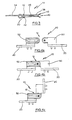
- FIG. 1 is an exploded perspective view of an electrical connector assembly in accordance with the present invention;
- FIG. 2 is a sectional view of the housing assembly as viewed generally along the line 2-2 of Fig. 1;
- FIG. 3 is a sectional view taken generally along line 3-3 of Fig. 1 and illustrating the cross- section of the female terminal of the assembly; and
- FIGS. 4a, 4b and 4c illustrate, in perspective, a variety of circuit board configurations which may be achieved using the connector assembly.
- With reference to the drawings, the
electrical connector assembly 10 uses a separable hinge construction. Theassembly 10 is seen to include a two-piece housing 12 fitted with a plurality of mating terminals which are distinguishable as afemale terminal 14 and amale terminal 16. In the example depicted, the connector assembly provides both a mechanical and electrical connection between a pair of like circuit elements, designated generally by thereference numeral 20. - The
circuit elements 20 comprise a relatively rigidinsulative substrate 22, on which a plurality ofcircuit paths 24 have been defined, theelements 20 being commonly referred to as circuit boards. Although not specifically shown, in a manner well known in the art thecircuit boards 20 may carry a number of circuit devices, and connection of the devices to other apparatus is provided by means ofcircuit path terminations 25 capable of forming electrical connections with theassembly 10. - The
terminals terminal body portion 30 from which an integral contact plate-like portion 32 extends. - To effect termination to the
circuit paths 24 of theboards 22, a generallyelongated pin 34 depends frombody portion 30. As best shown in Fig. 1, thesepins 34 may be so disposed with respect to theterminal body 30 inadjacent terminals terminals circuit paths 24. Alocking lance 36 extends from a side of eachterminal - With reference now to Figs. 1 and 3, the
female terminal 14 can be seen to include a reverselybent plate portion 38, defining, essentially, a double-walled receptacle 40 for slidingly receiving thecontact portion 32 of themale terminal 16. The edges ofcontact portion 32 of thefemale terminal 14 are formed withlips 42 turned generally outwardly in relation to thereceptacle 40. In addition to strengthening theterminal 14, thelips 42 serve as guides for insertion of themale terminal 16 therebetween. Insertion is also enhanced bychamfered edges 44 of themale terminal 16.Protrusions 46 are formed inplate portion 38 and extend inwardly into thereceptacle 40 for reasons which will be described, hereinafter. - The
housing 12 is molded from suitable dielectric material and comprises two distinct pieces, i.e. aportion 50 for mountingfemale terminals 14 and aportion 52 for mountingmale terminals 16. Although theterminals housing 12 provides for a more mechanically stable assembly, in thatcavities 54 of thehousing portions terminals 14 in isolated, immovable relationship one with respect to the other. Further, and as best seen in Fig. 2,apertures 56 formed in the underside of thehousing portions pin portions 34 of theterminals Suitable lands 58 are formed within thecavities 54 for co-operation with thelocking lances 36 thereby preventing withdrawal of theterminals housing 12. - In order to facilitate a separable hinge relationship between the
terminals female housing portion 50 is adapted with a pair oftrunnions 62 aligned along a predetermined axis of rotation, designated generally by thereference numeral 64. Correspondingly, themale housing portion 52 is configured with acomplementary yoke 66 comprising a pair ofarms 68 having suitably shaped and dimensionedapertures 70 for journalling of thetrunnions 62. Thearms 68 are sufficiently resilient such that they can be force fitted by manipulation into or out of engagement with thetrunnions 62 when separation or rejoining of thehousing portions - The axis of
rotation 64 is so disposed with respect to thehousing 12 that the contact surfaces of the plate-like contact portions 32 of pairs ofmating terminals protrusions 46 are preferably centred on the axis ofrotation 64, thereby minimizing relative movement at the contact interface between theterminals - It can be appreciated that extremely high contact forces are achievable between the
terminals cavities 54 of thefemale housing portion 50. With thecavities 54 sufficiently narrow, thereceptacle 40 will assume a biased state upon insertion of themale terminal 16, due to natural resilience of thehousing 50, generally. Likewise, inherent resilience of theprotrusions 46 contributes to the biasing together of theterminals - From the foregoing description, it should be apparent that the
instant connector assembly 10 provides a means for selectively coupling a pair of circuit members in pivotable relation, with reliable mechanical and electrical stability. Although a pair of circuit boards has been illustrated, thecircuit elements 20 may consist of virtually any apparatus which requires electrical connection to another member. As illustrated in Figs. 4a, 4b and 4c a wide range of flexure and extension modes as between the twoelements 20 is made possible by theconnector 10. The described pivoting movements may be repeated over numerous cycles without appreciable wearing of the contact interface due to the action of theprotrusions 46, as described above.
Claims (5)
Applications Claiming Priority (2)
| Application Number | Priority Date | Filing Date | Title |
|---|---|---|---|
| JP178343/83 | 1983-09-28 | ||
| JP58178343A JPS6079681A (en) | 1983-09-28 | 1983-09-28 | Electric connector with hinge |
Publications (2)
| Publication Number | Publication Date |
|---|---|
| EP0142922A1 EP0142922A1 (en) | 1985-05-29 |
| EP0142922B1 true EP0142922B1 (en) | 1987-07-08 |
Family
ID=16046833
Family Applications (1)
| Application Number | Title | Priority Date | Filing Date |
|---|---|---|---|
| EP84306451A Expired EP0142922B1 (en) | 1983-09-28 | 1984-09-21 | Hingeable electrical connector |
Country Status (4)
| Country | Link |
|---|---|
| US (1) | US4657320A (en) |
| EP (1) | EP0142922B1 (en) |
| JP (1) | JPS6079681A (en) |
| DE (1) | DE3464673D1 (en) |
Cited By (2)
| Publication number | Priority date | Publication date | Assignee | Title |
|---|---|---|---|---|
| DE19804453A1 (en) * | 1998-02-05 | 1999-08-12 | Itt Mfg Enterprises Inc | Floating mounted connector for connecting electrical assemblies |
| CN101578739B (en) * | 2007-01-08 | 2011-12-07 | 泰科电子公司 | Connector assembly for end mounting panel members |
Families Citing this family (63)
| Publication number | Priority date | Publication date | Assignee | Title |
|---|---|---|---|---|
| JPS60109187A (en) * | 1983-11-11 | 1985-06-14 | アムプ インコ−ポレ−テッド | Electric connector |
| JPS60166985U (en) * | 1984-04-12 | 1985-11-06 | 星電器製造株式会社 | Connector for printed circuit board connection |
| DE3581265D1 (en) * | 1984-10-31 | 1991-02-14 | Siemens Ag | REAR WALL WIRING FOR ELECTRICAL ASSEMBLIES. |
| DE3447362A1 (en) * | 1984-12-24 | 1986-07-03 | International Gulf Venture S.A., Luxemburg | ELECTRICALLY CONDUCTIVE CONNECTION IN A NARROW SPACE BETWEEN TWO MOVING COMPONENTS |
| JPH043433Y2 (en) * | 1985-02-19 | 1992-02-03 | ||
| JP2604719B2 (en) * | 1986-05-06 | 1997-04-30 | ソニー株式会社 | Connector device |
| JPH0244470Y2 (en) * | 1986-07-04 | 1990-11-26 | ||
| JPS6312178U (en) * | 1986-07-11 | 1988-01-26 | ||
| US4728760A (en) * | 1986-08-11 | 1988-03-01 | Fmc Corporation | Induction heating pressure welding with rotary bus bar joint |
| US4714808A (en) * | 1986-09-02 | 1987-12-22 | Fmc Corporation | Induction heating pressure welding with linear bus bar joint |
| JPS6373874U (en) * | 1986-11-04 | 1988-05-17 | ||
| US4701133A (en) * | 1987-01-21 | 1987-10-20 | Continental-Wirt Electronics Corporation | Hermaphroditic connector |
| JPS63218174A (en) * | 1987-03-07 | 1988-09-12 | 日本航空電子工業株式会社 | Rotary mating/unmating connector |
| US4863387A (en) * | 1987-12-22 | 1989-09-05 | Snaper Alvin A | Printer circuit board separable connector |
| JPH06101358B2 (en) * | 1988-01-22 | 1994-12-12 | アンプ インコーポレーテッド | Hinge connector |
| JPH067594Y2 (en) * | 1988-03-31 | 1994-02-23 | アンプ インコーポレーテッド | Electric hinge connector |
| US4863388A (en) * | 1988-05-04 | 1989-09-05 | Ag Communication Systems Corporation | Rotating contact ZIF connector |
| JPH0451434Y2 (en) * | 1988-06-17 | 1992-12-03 | ||
| US5174761A (en) * | 1989-01-30 | 1992-12-29 | Amp Incorporated | Electrical connector |
| US4975062A (en) * | 1989-05-19 | 1990-12-04 | Motorola, Inc. | Hermaphroditic connector |
| GB2237152B (en) * | 1989-09-29 | 1993-12-01 | Motorola Gmbh | Improvements in or relating to circuit carriers |
| JPH03112891U (en) * | 1990-03-01 | 1991-11-19 | ||
| DE4130882C1 (en) * | 1991-09-17 | 1993-01-07 | Kloeckner-Moeller Gmbh, 5300 Bonn, De | |
| US5212907A (en) * | 1992-10-13 | 1993-05-25 | Ed Van Sandt | Door including electrical device and pivotable conductor therefor |
| US5542850A (en) * | 1994-06-30 | 1996-08-06 | The Whitaker Corporation | Pivotal electrical connector |
| JP3112235B2 (en) * | 1994-09-19 | 2000-11-27 | 矢崎総業株式会社 | ID connector |
| JP3025387U (en) * | 1995-12-01 | 1996-06-11 | トーマス アンド ベッツ コーポレーション | connector |
| US5674078A (en) * | 1996-01-23 | 1997-10-07 | The Whitaker Corporation | Multi-directional interface header assembly |
| US5971785A (en) * | 1997-08-22 | 1999-10-26 | Molex Incorporated | Hermaphroditic connector for printed circuit boards |
| US6074230A (en) * | 1998-03-23 | 2000-06-13 | Molex Incorporated | Hermaphroditic electrical connectors |
| JP2000195597A (en) | 1998-12-25 | 2000-07-14 | Thomas & Betts Corp <T&B> | Earth terminal |
| US6162081A (en) * | 1999-03-19 | 2000-12-19 | Molex Incorporated | Electrical connector terminal arrangement |
| US6244887B1 (en) | 1999-03-19 | 2001-06-12 | Molex Incorporated | Electrical connector assembly |
| US6386884B1 (en) * | 2000-05-12 | 2002-05-14 | Northstar Systems, Inc. | Rotatable connector system |
| US6561853B1 (en) * | 2001-12-26 | 2003-05-13 | Hon Hai Precision Ind. Co., Ltd. | Electrical connector assembly |
| USD472879S1 (en) | 2002-02-14 | 2003-04-08 | Mitsumi Electric Co., Ltd. | Electric connector |
| JP4817759B2 (en) * | 2005-08-26 | 2011-11-16 | 矢崎総業株式会社 | Vehicle swing structure connector and vehicle swing structure |
| CN100530032C (en) * | 2006-04-05 | 2009-08-19 | 鸿富锦精密工业(深圳)有限公司 | Main board |
| US7387521B1 (en) * | 2006-12-22 | 2008-06-17 | Tyco Electronics Corporation | Connector assembly for end mounting panel members |
| SG149730A1 (en) * | 2007-07-30 | 2009-02-27 | Molex Inc | Inverse coplanar electrical connector |
| JP5248398B2 (en) * | 2009-04-07 | 2013-07-31 | 富士通コンポーネント株式会社 | connector |
| CN101924287B (en) * | 2009-08-05 | 2014-03-12 | 安费诺东亚电子科技(深圳)有限公司 | Guillotine-type connector |
| US7924558B2 (en) * | 2009-08-31 | 2011-04-12 | International Business Machines Corporation | Insertion and rotation connector |
| JP2011090856A (en) * | 2009-10-22 | 2011-05-06 | Molex Inc | Base-to-base connector |
| US20110130043A1 (en) * | 2009-11-27 | 2011-06-02 | Wan-Tien Chen | Combination of socket and plug for battery connector |
| US7874845B1 (en) * | 2010-02-04 | 2011-01-25 | Amphenol East Asia Electronic Technology (Shenzhen) Ltd. | Scissor-type multi-functional connector |
| JP4719305B1 (en) * | 2010-08-27 | 2011-07-06 | イリソ電子工業株式会社 | connector |
| JP5775335B2 (en) * | 2011-03-16 | 2015-09-09 | 矢崎総業株式会社 | Butt connector |
| JP5551116B2 (en) * | 2011-06-17 | 2014-07-16 | ケル株式会社 | Connector device |
| JP5551115B2 (en) * | 2011-06-17 | 2014-07-16 | ケル株式会社 | Connector device |
| MX2014001670A (en) * | 2011-09-16 | 2014-05-27 | Framatome Connectors Int | Hingeable connector assembly. |
| TWM458706U (en) * | 2012-10-11 | 2013-08-01 | Molex Taiwan Ltd | Electrical connection device |
| US8727790B1 (en) * | 2012-11-01 | 2014-05-20 | Avx Corporation | Board-to board connectors with integral detachable transfer carrier plate |
| US10051724B1 (en) | 2014-01-31 | 2018-08-14 | Apple Inc. | Structural ground reference for an electronic component of a computing device |
| US9525222B2 (en) | 2014-04-11 | 2016-12-20 | Apple Inc. | Reducing or eliminating board-to-board connectors |
| US9666967B2 (en) * | 2014-07-28 | 2017-05-30 | Apple Inc. | Printed circuit board connector for non-planar configurations |
| DE102015116490A1 (en) * | 2014-11-19 | 2016-05-19 | Rosenberger Hochfrequenztechnik Gmbh & Co. Kg | Magnetic connection device |
| US10945664B1 (en) | 2015-09-30 | 2021-03-16 | Apple, Inc. | Protective case with coupling gasket for a wearable electronic device |
| DE102015120280A1 (en) * | 2015-11-24 | 2017-05-24 | Werma Holding Gmbh + Co. Kg | Signal device with light module |
| CN108493649A (en) * | 2018-03-14 | 2018-09-04 | 郑州云海信息技术有限公司 | A kind of non-directional adjustable connector |
| AU2019307236A1 (en) | 2018-07-20 | 2021-02-18 | Clearvue Technologies Ltd | A device for generating electricity |
| DE102020101981B4 (en) | 2020-01-28 | 2022-05-25 | Phoenix Contact Gmbh & Co. Kg | Arrangement with electrical elements and a connecting device |
| CN117293575A (en) * | 2020-03-26 | 2023-12-26 | 上海莫仕连接器有限公司 | Electrical connection devices and terminals |
Family Cites Families (13)
| Publication number | Priority date | Publication date | Assignee | Title |
|---|---|---|---|---|
| US3376479A (en) * | 1965-04-30 | 1968-04-02 | Sperry Rand Corp | Means for operatively connecting printed circuit boards |
| ES367933A1 (en) * | 1968-06-15 | 1971-04-16 | Amp Inc | Connector housing assemblies |
| US3691430A (en) * | 1971-04-29 | 1972-09-12 | Allen Bradley Co | Circuit board assembly with positive latch |
| SU376848A1 (en) * | 1971-07-05 | 1973-04-05 | PLUG | |
| US3853380A (en) * | 1973-05-15 | 1974-12-10 | Amp Inc | Angularly positionable electrical contact housing |
| US4036544A (en) * | 1974-10-16 | 1977-07-19 | Bunker Ramo Corporation | Contact for multiple conductor connector |
| US3923365A (en) * | 1974-11-05 | 1975-12-02 | Amp Inc | Press fitted terminal post |
| AU4921379A (en) * | 1978-07-31 | 1980-02-07 | Bunker Ramo Corporation | Feed-through electrical connector |
| US4273401A (en) * | 1979-07-06 | 1981-06-16 | Leonard Katzin | Zero insertion force electrical connector |
| JPS581982Y2 (en) * | 1979-07-30 | 1983-01-13 | 東海電線株式会社 | Composite flat terminal |
| JPS57127491U (en) * | 1981-02-02 | 1982-08-09 | ||
| JPS5835274U (en) * | 1981-09-01 | 1983-03-08 | 三洋電機株式会社 | connector |
| US4506940A (en) * | 1983-06-17 | 1985-03-26 | Amp Incorporated | Input/output intercard connector |
-
1983
- 1983-09-28 JP JP58178343A patent/JPS6079681A/en active Granted
-
1984
- 1984-08-13 US US06/639,762 patent/US4657320A/en not_active Expired - Lifetime
- 1984-09-21 EP EP84306451A patent/EP0142922B1/en not_active Expired
- 1984-09-21 DE DE8484306451T patent/DE3464673D1/en not_active Expired
Cited By (2)
| Publication number | Priority date | Publication date | Assignee | Title |
|---|---|---|---|---|
| DE19804453A1 (en) * | 1998-02-05 | 1999-08-12 | Itt Mfg Enterprises Inc | Floating mounted connector for connecting electrical assemblies |
| CN101578739B (en) * | 2007-01-08 | 2011-12-07 | 泰科电子公司 | Connector assembly for end mounting panel members |
Also Published As
| Publication number | Publication date |
|---|---|
| US4657320A (en) | 1987-04-14 |
| JPS6079681A (en) | 1985-05-07 |
| EP0142922A1 (en) | 1985-05-29 |
| DE3464673D1 (en) | 1987-08-13 |
| JPH022271B2 (en) | 1990-01-17 |
Similar Documents
| Publication | Publication Date | Title |
|---|---|---|
| US4657320A (en) | Hingeable electrical connector | |
| US12531363B2 (en) | Connector assembly | |
| EP0510995B1 (en) | Electrical connector having reliable terminals | |
| US5915975A (en) | Surface mount connector with integrated power leads | |
| EP0561642B1 (en) | Electrical connector | |
| US4818237A (en) | Modular plug-in connection means for flexible power supply of electronic apparatus | |
| EP0107288B1 (en) | Electrical connector assembly for terminating flat shielded electrical cable | |
| EP0292538B1 (en) | Impedance matched electrical connector | |
| US4867690A (en) | Electrical connector system | |
| KR940002008B1 (en) | Hinged electrical connector | |
| US5413491A (en) | Small form factor connectors with center ground plate | |
| EP1554784A1 (en) | Modular coaxial electrical interconnect | |
| WO2003067711B1 (en) | High speed differential signal edge card connector circuit board layouts | |
| EP0140473B1 (en) | Solderless circuit board conductor and connector assemblies employing same | |
| US7438556B2 (en) | Electrical interconnection between multiple printed circuit boards | |
| EP0251515B1 (en) | Hingeable electrical connector assembly | |
| EP0562854B1 (en) | Electrical connector | |
| CA1128619A (en) | Circuit board interconnection system | |
| US5127838A (en) | Plated electrical connectors | |
| US4299433A (en) | Cable connector | |
| US4679890A (en) | Connector contact terminal | |
| US6629853B2 (en) | Self-aligning power connector system | |
| US3887259A (en) | Connector retaining adapter | |
| US4494818A (en) | Mounting member for electrical contacts | |
| US4772211A (en) | Multi-plane interconnection system |
Legal Events
| Date | Code | Title | Description |
|---|---|---|---|
| PUAI | Public reference made under article 153(3) epc to a published international application that has entered the european phase |
Free format text: ORIGINAL CODE: 0009012 |
|
| AK | Designated contracting states |
Designated state(s): DE FR GB IT NL SE |
|
| 17P | Request for examination filed |
Effective date: 19850702 |
|
| 17Q | First examination report despatched |
Effective date: 19860512 |
|
| ITF | It: translation for a ep patent filed | ||
| GRAA | (expected) grant |
Free format text: ORIGINAL CODE: 0009210 |
|
| AK | Designated contracting states |
Kind code of ref document: B1 Designated state(s): DE FR GB IT NL SE |
|
| REF | Corresponds to: |
Ref document number: 3464673 Country of ref document: DE Date of ref document: 19870813 |
|
| ET | Fr: translation filed | ||
| PLBE | No opposition filed within time limit |
Free format text: ORIGINAL CODE: 0009261 |
|
| STAA | Information on the status of an ep patent application or granted ep patent |
Free format text: STATUS: NO OPPOSITION FILED WITHIN TIME LIMIT |
|
| 26N | No opposition filed | ||
| ITTA | It: last paid annual fee | ||
| EAL | Se: european patent in force in sweden |
Ref document number: 84306451.0 |
|
| PGFP | Annual fee paid to national office [announced via postgrant information from national office to epo] |
Ref country code: NL Payment date: 19990630 Year of fee payment: 16 |
|
| PGFP | Annual fee paid to national office [announced via postgrant information from national office to epo] |
Ref country code: GB Payment date: 19990806 Year of fee payment: 16 |
|
| PGFP | Annual fee paid to national office [announced via postgrant information from national office to epo] |
Ref country code: SE Payment date: 19990901 Year of fee payment: 16 Ref country code: FR Payment date: 19990901 Year of fee payment: 16 |
|
| PGFP | Annual fee paid to national office [announced via postgrant information from national office to epo] |
Ref country code: DE Payment date: 19990927 Year of fee payment: 16 |
|
| PG25 | Lapsed in a contracting state [announced via postgrant information from national office to epo] |
Ref country code: GB Free format text: LAPSE BECAUSE OF NON-PAYMENT OF DUE FEES Effective date: 20000921 |
|
| PG25 | Lapsed in a contracting state [announced via postgrant information from national office to epo] |
Ref country code: SE Free format text: THE PATENT HAS BEEN ANNULLED BY A DECISION OF A NATIONAL AUTHORITY Effective date: 20000929 |
|
| PG25 | Lapsed in a contracting state [announced via postgrant information from national office to epo] |
Ref country code: NL Free format text: LAPSE BECAUSE OF NON-PAYMENT OF DUE FEES Effective date: 20010401 |
|
| GBPC | Gb: european patent ceased through non-payment of renewal fee |
Effective date: 20000921 |
|
| EUG | Se: european patent has lapsed |
Ref document number: 84306451.0 |
|
| PG25 | Lapsed in a contracting state [announced via postgrant information from national office to epo] |
Ref country code: FR Free format text: LAPSE BECAUSE OF NON-PAYMENT OF DUE FEES Effective date: 20010531 |
|
| NLV4 | Nl: lapsed or anulled due to non-payment of the annual fee |
Effective date: 20010401 |
|
| PG25 | Lapsed in a contracting state [announced via postgrant information from national office to epo] |
Ref country code: DE Free format text: LAPSE BECAUSE OF NON-PAYMENT OF DUE FEES Effective date: 20010601 |
|
| REG | Reference to a national code |
Ref country code: FR Ref legal event code: ST |