EP0142897A1 - Magnetic-tape cassette - Google Patents
Magnetic-tape cassette Download PDFInfo
- Publication number
- EP0142897A1 EP0142897A1 EP84201649A EP84201649A EP0142897A1 EP 0142897 A1 EP0142897 A1 EP 0142897A1 EP 84201649 A EP84201649 A EP 84201649A EP 84201649 A EP84201649 A EP 84201649A EP 0142897 A1 EP0142897 A1 EP 0142897A1
- Authority
- EP
- European Patent Office
- Prior art keywords
- cover
- magnetic
- housing
- recess
- front cover
- Prior art date
- Legal status (The legal status is an assumption and is not a legal conclusion. Google has not performed a legal analysis and makes no representation as to the accuracy of the status listed.)
- Granted
Links
- 210000002105 tongue Anatomy 0.000 claims description 17
- 238000010276 construction Methods 0.000 description 6
- 230000005540 biological transmission Effects 0.000 description 1
- 239000000356 contaminant Substances 0.000 description 1
- 239000000428 dust Substances 0.000 description 1
- 230000037431 insertion Effects 0.000 description 1
- 238000003780 insertion Methods 0.000 description 1
- 239000000463 material Substances 0.000 description 1
- 230000035515 penetration Effects 0.000 description 1
- 230000002441 reversible effect Effects 0.000 description 1
Images

Classifications
-
- G—PHYSICS
- G11—INFORMATION STORAGE
- G11B—INFORMATION STORAGE BASED ON RELATIVE MOVEMENT BETWEEN RECORD CARRIER AND TRANSDUCER
- G11B23/00—Record carriers not specific to the method of recording or reproducing; Accessories, e.g. containers, specially adapted for co-operation with the recording or reproducing apparatus ; Intermediate mediums; Apparatus or processes specially adapted for their manufacture
- G11B23/02—Containers; Storing means both adapted to cooperate with the recording or reproducing means
- G11B23/04—Magazines; Cassettes for webs or filaments
- G11B23/08—Magazines; Cassettes for webs or filaments for housing webs or filaments having two distinct ends
- G11B23/087—Magazines; Cassettes for webs or filaments for housing webs or filaments having two distinct ends using two different reels or cores
- G11B23/08707—Details
- G11B23/08735—Covers
Definitions
- the invention relates to a magnetic-tape cassette having a housing which comprises two substantially parallel major walls each having two openings for the passage of drive spindles of a magnetic-tape cassette apparatus, substantially parallel first and second side walls, a rear wall and a front wall along which part of a magnetic tape extends, and a front cover comprising a major portion which, when said cover is in the closed position, covers said part of the magnetic tape, and first and second cover flanges which are situated one on each side of the major portion adjacent said first and second side walls respectively and which are pivotally connected to said side walls, the front cover being pivotable about a pivotal axis perpendicular to said side walls from the closed position to a first open position in which the major portion of the cover is situated near one of the major walls of the housing or to a second open position in which said major portion is situated near the other of said major walls, latching means being provided for latching the front cover in the closed position.
- a magnetic-tape cassette of the above type is disclosed in the Applicants'.Netherlands Patent Specification 165598 (PHN.9121).
- the front cover of this known magnetic-tape cassette is latched in the closed position by a spring-loaded slide which is slid onto the housing.
- the slide is slidable in a direction perpendicular to the front wall of the housing and has two funnel-shaped recesses which position projections on the cover flanges in an end position of the slide and thus act as latching means to latch the front cover in the closed position.
- the slide In order to release the front cover the slide must be slid away from the front wall of the housing. This movement can be performed in a reliable manner only by simultaneously exerting pressure on the slide at two locations near the two side walls of the housing.
- each of the cover flanges is formed with a recess which extends arcuately about the pivotal axis of the front cover
- the latching means comprise first and second spring-loaded latching projections which are situated near the first and second side wall respectively of the case-cassette housing and are movable independently into and out of the recesses in the first and second cover flanges respectively in directions substantially perpendicular to the side walls, in the closed position of the front cover the latching projections are each engaged in a first end portion of the recess in the respective cover flange and together retain the cover in the closed position, and the recesses in the cover flanges are so arranged that when projected onto a plane perpendicular to the pivotal axis of the front cover they are substantially mirror-symmetrical relative to each other about a plane containing said pivotal axis and extending parallel to the major walls of the housing and said first end portions of the recesses overlap
- the front cover can be unlatched by moving one of the latching projections out of the recess in the adjacent cover flange. Since the other latching projection can now slide in the recess in the other cover flange, the front cover can now be pivoted into one of the open positions. For swinging the cover into the other open position it is necessary only to move the other latching projection out of the respective recess, since now the first latching projection can slide in the associated recess. In the latched position the two latching projections, which are each situated in an end portion of the associated recess, ensure that a stable latching is obtained.
- United States Patent Specification 4,302,787 proposes a magnetic-tape cassette comprising cover flanges with recesses which engage projections.
- these projections do not serve for latching the front cover of this magnetic-tape cassette; they are intended for limiting the pivotal movement of the cover towards the open position and for urging the cover towards the closed position through a spring construction.
- a preferred embodiment of the invention is characterized in that the recess in each cover flange extends through an arc of approximately 90° about the pivotal axis, and the end wall of a second end portion of each recess remote from the first end portion thereof limits the pivotal movement of the front cover in one direction or the other to define the first or the second open position.
- the front cover can be pivoted in such a manner, unimpeded by the second latching projection, that in the open position the major portion of the front cover extends substantially parallel to the adjacent major wall of the housing.
- each cover flange in the side facing the adjacent side wall of the housing each cover flange has a second recess which is disposed substantially diametrically opposite the second end portion of the first recess in that flange and, in which the latching projection associated with that flange engages in the first or second open position of the front cover to latch the cover in that position.
- the front cover is thus held in a stable position when it is open. Consequently, the magnetic tape-cassette apparatus need not be provided with means for retaining the cover in the open position.
- first and second latching projections are situated at the free ends of first and second resilient tongues connected to the first and second side walls respectively of the housing and are engageable in the recesses in the cover flanges under the influence of the spring forces exerted by the tongues. This simplifies the construction of the latching projections, which can be manufactured integrally with the side walls of the housing.
- each tongue is provided with an actuating element which projects from a plane containing the outer surface of the side wall to which the tongue is connected.
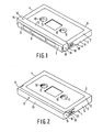
- the magnetic-tape cassette shown in Figs. 1 and 2 comprises a housing having two substantially parallel rectangular major walls 2 and 3.
- the housing 1 further comprises two substantially parallel rectangular side walls 4 and 5, a rear wall 6, and a front wall 7 which extends parallel to this rear wall.
- the front wall 7 is formed with three front openings 8.
- Part of magnetic tape 9 extends tautly along the front wall 7 in the area behind the front openings 8 to cooperate with components, not shown, of a magnetic-tape-cassette apparatus. These components comprise, for example, magnetic heads, a pressure roller and a capstan.
- the magnetic cape 9 is wound on two hubs 10 which are mounted for notation between the two major walls 2 and 3.
- the cassette shown in the drawings further comprises a front cover 12, which has an elongate major portion 13 which, in the closed position of the cover, as shown in Fig. 2 covers the part of the magnetic tape 9 which extends along the front wall 7.
- the cover 12 compr3ses a cover flange 14 respectively 15, which cover flanges are situated adjacent the side walls 4 and 5 respectively and are pivotally connected to the side walls by means of journals 16 on these side walls.
- the common axis 16a of the journals 16 forms the pivotal axis of the front cover and extends perpendicularly to the side walls 4 and 5.
- each of the side walls 4 and 5 a resilient tongue 18 is formed which extends longitudinally of the side wall, parallel to the major walls 2 and 3, and which is integral with the cassette housing.
- the end of each tongue which is nearer the rear wall 6 is connected to the relevant side wall.
- the resilience of the tongue is determined by the choice of the material of the housing.
- a projection 19 and 20 respectively is formed on the free end of each tongue 17 and 18, which is the end nearer the front wall 7. By deflection of the respective tongue 17 or 18, each projection 19 and 20 is movable substantially perpendicularly to the relevant side wall.
- the tongues17 and 18 act as leaf springs to urge the projections 19 and 20 against the inner sides of the cover flanges 14 and 15 respectively.
- each projection 19 and 20 engages in a first end portion of a recess 21, 22 respectively in the inner side of the adjacent cover flange 14 or 15.
- the recesses 21 and 22 extend arcuately about the pivotal axis 16a and open out of semi-circular edge portions 23 and 24 of the cover flanges 14 and 15 respectively, in the radial direction, the edge portions 23 and 24 being concentric with the recesses 21 and 22.
- oblique edge portions 13a and 13b of the major portion 13 of the front cover 12 preferably effectively abut the front edges of the major walls 2 and 3 respectively in the closed position of the front cover.
- the front cover In the closed position the front cover is latched against movement to either of the two open positions by the action of the projections 19 and 20, which function as latching projections.
- the recesses 21 and 22 are so arranged that when projected onto a plane perpendicular to the pivotal axis 16a they are mirror-symmetrical relative to each other about a plane containing the axis 16a and extending parallel to the major walls 2 and 3 of the cassette housing, said first end portions of the recesses overlapping each other in this projection (compare Figs. 3A and 3B).
- the projection 19 In the closed position of the front cover the projection 19 abuts the end wall of the first end portion of the recess 21, whilst the projection 20 abuts the end wall of the first end portion of the recess 22, thereby ensuring a stable positioning of the front cover 12. Owing to the mirror-symmetrical arrangement of the recesses 21 and 22 it is possible to release the front cover 12 for pivotal movement into one of the two open positions by pressing in only one of the projections 19 and 20.
- the tongues 17 and 18 are provided with actuating elements 25 and 26 respectively, which elements, shown in particular in Figs. 6 and 7, project from planes containing the outer surfaces of the side walls 4 and 5 respectively of the cassette housing.
- the associated projection 19 or 20 is disengaged from the respective recess 21 or 22. If the projection 19 is disengaged the cover 12 can pivot to the first open position as shown in Fig. 4, the projection 20 sliding freely in the recess 22; if the projection 20 is disengaged the cover 12 can pivot to the second open position as shown in Fig. 5, the pojection 19 sliding in the recess 21.
- each recess extends through an arc of approximately 90 0 about the pivotal axis 16a, so that the end wall of a second end portion of the recess remote from the first end portion thereof limits the pivotal movement of "the cover correspondingly in one or the other direction to define the first or second open position respectively.
- each cover flange 14 and 15 is formed with a secondrecess 27, 28 respectively which is situated substantially diametrically opposite the second end portion of the first recess 21 or 22 in the respective cover flange and opens out of the semi-circular edge portion 23 or 24 of the flange and in which the respective projection 19 or 20 can engage when the cover 12 is swung into the first or the second open position respectively. In this way the cover is latched effectively in the open positions.
- each second recess 27 and 28 is bounded by a ramp 27a and 28a respectively at the side adjacent the first end portion of the associated first recess 21 or 22.
- the front cover 12 of a magnetic-tape cassette in accordance with the invention has the advantage that a stable latching in the closed positions of the cover is obtained, whilst pressing in only one of the actuating elements 25 or 26 is sufficientto release the cover 12 for movement in the desired direction.
- This is of special advantage in reversible cassettes, which can be placed on or in a magnetic-tape-cassette apparatus with the openings 11 in either of the two major walls 2 and 3 of the cassette housing 1 positioned to receive the drive spindles of the apparatus.
- the housing 1 may have a symmetrical construction and that on the housing, of which the tongues 17 and 18 with the projections 19 and 20 form integral parts, only one separate part has to be mounted, namely the front cover 12.
- the cover can pivot in one direction only, so that no undesired movements of the cover are possible.
- the space occupied by the cover in the open position above or below the housing respectively is small, so that in the apparatus only a comparatively small space is necessary for the movementof the cover to the first or the second open position.
- the cassette shown may be employed, for example, for digital audio recording on magnetic tapes, for which purpose the housing must be sealed effectively against the penetration of dust and other contaminants when the cassette is not in use.
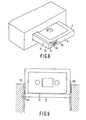
- the cassette in accordance with the invention can be inserted in different ways into a magnetic-tape-cassette apparatus.
- FIG. 8 shows the cassette being inserted with one of the side walls of the cassette housing, in this case the side wall 4, facing the apparatus.
- a stop inside the apparatus then presses the actuating element 25 inwards to disengage the projection 19 from the recess 21 so that the cover 12 can be swung into the first open position in the apparatus.
- This is particularly suitable for equipment used in cars, in which the cassette is generally inserted in this way.
- Fig. 9 shows that the cassette can also be inserted with a long side facing the apparatus, oneor the other of the actuating elements 25 and 26, in this case the element 25, being actuated during the insertion by a projection 29 inside the apparatus. During the passage of the relevant actuating element past the projection 29 the cover can be swung into the relevant open position.
Landscapes
- Packaging Of Annular Or Rod-Shaped Articles, Wearing Apparel, Cassettes, Or The Like (AREA)
Abstract
Description
- The invention relates to a magnetic-tape cassette having a housing which comprises two substantially parallel major walls each having two openings for the passage of drive spindles of a magnetic-tape cassette apparatus, substantially parallel first and second side walls, a rear wall and a front wall along which part of a magnetic tape extends, and a front cover comprising a major portion which, when said cover is in the closed position, covers said part of the magnetic tape, and first and second cover flanges which are situated one on each side of the major portion adjacent said first and second side walls respectively and which are pivotally connected to said side walls, the front cover being pivotable about a pivotal axis perpendicular to said side walls from the closed position to a first open position in which the major portion of the cover is situated near one of the major walls of the housing or to a second open position in which said major portion is situated near the other of said major walls, latching means being provided for latching the front cover in the closed position.
- A magnetic-tape cassette of the above type is disclosed in the Applicants'.Netherlands Patent Specification 165598 (PHN.9121). The front cover of this known magnetic-tape cassette is latched in the closed position by a spring-loaded slide which is slid onto the housing. The slide is slidable in a direction perpendicular to the front wall of the housing and has two funnel-shaped recesses which position projections on the cover flanges in an end position of the slide and thus act as latching means to latch the front cover in the closed position. In order to release the front cover the slide must be slid away from the front wall of the housing. This movement can be performed in a reliable manner only by simultaneously exerting pressure on the slide at two locations near the two side walls of the housing. For this movement of the slide and hence for unlatching the front cover a comparatively bulky mechanism is required on the magnetic-tape-cassette apparatus, whilst for a correct co-operation with the actuating mechanism the known cassette is preferably inserted into the apparatus with the front wall facing the apparatus.
- It is the object of the invention to enable the unlatching of the front cover of such a magnetic-tape cassette to be actuated at a location near just one side wall of the housing.
- To this end the invention is characterized in that in the side facing the adjacent side wall of the housing, each of the cover flanges is formed with a recess which extends arcuately about the pivotal axis of the front cover, the latching means comprise first and second spring-loaded latching projections which are situated near the first and second side wall respectively of the case-cassette housing and are movable independently into and out of the recesses in the first and second cover flanges respectively in directions substantially perpendicular to the side walls, in the closed position of the front cover the latching projections are each engaged in a first end portion of the recess in the respective cover flange and together retain the cover in the closed position, and the recesses in the cover flanges are so arranged that when projected onto a plane perpendicular to the pivotal axis of the front cover they are substantially mirror-symmetrical relative to each other about a plane containing said pivotal axis and extending parallel to the major walls of the housing and said first end portions of the recesses overlap each other.
- Thus, the front cover can be unlatched by moving one of the latching projections out of the recess in the adjacent cover flange. Since the other latching projection can now slide in the recess in the other cover flange, the front cover can now be pivoted into one of the open positions. For swinging the cover into the other open position it is necessary only to move the other latching projection out of the respective recess, since now the first latching projection can slide in the associated recess. In the latched position the two latching projections, which are each situated in an end portion of the associated recess, ensure that a stable latching is obtained. Thus, for unlatchingthe front cover of a magnetic-tape cassette in accordance with the invention, it is sufficient to actuate the latching projection corresponding to the direction in which the cover is to be pivoted. This enables the magnetic-tape cassette to be used in a magnetic-tape-cassette apparatus in which space for unlatching the front cover is available at only one location inside the apparatus. This is the case, for example, in an apparatus into which the cassette has to be inserted with one of the side walls of the cassette housing, facing the apparatus. It is then also of advantage that the cover can be opened in such a manner that in the open position it occupies only a small amount of additional space adjacent the relevant major wall of the cassette housing. A further advantage is that for latching the front cover a simple construction comprising only a few parts is required, so that this construction is particularly suitable for mass-manufactured magnetic-tape cassettes.
- It is to be noted that United States Patent Specification 4,302,787 proposes a magnetic-tape cassette comprising cover flanges with recesses which engage projections. However, these projections do not serve for latching the front cover of this magnetic-tape cassette; they are intended for limiting the pivotal movement of the cover towards the open position and for urging the cover towards the closed position through a spring construction.
- A preferred embodiment of the invention is characterized in that the recess in each cover flange extends through an arc of approximately 90° about the pivotal axis, and the end wall of a second end portion of each recess remote from the first end portion thereof limits the pivotal movement of the front cover in one direction or the other to define the first or the second open position. Thus, after the first latching projection has been moved out of the respective recess, the front cover can be pivoted in such a manner, unimpeded by the second latching projection, that in the open position the major portion of the front cover extends substantially parallel to the adjacent major wall of the housing.
- In this respect another embodiment of the invention is characterized in that in the side facing the adjacent side wall of the housing each cover flange has a second recess which is disposed substantially diametrically opposite the second end portion of the first recess in that flange and, in which the latching projection associated with that flange engages in the first or second open position of the front cover to latch the cover in that position. The front cover is thus held in a stable position when it is open. Consequently, the magnetic tape-cassette apparatus need not be provided with means for retaining the cover in the open position.
- Yet another embodiment of the invention is characterized in that the first and second latching projections are situated at the free ends of first and second resilient tongues connected to the first and second side walls respectively of the housing and are engageable in the recesses in the cover flanges under the influence of the spring forces exerted by the tongues. This simplifies the construction of the latching projections, which can be manufactured integrally with the side walls of the housing.
- A simple lateral actuation of the relevant latching projection is possible if each tongue is provided with an actuating element which projects from a plane containing the outer surface of the side wall to which the tongue is connected.
- A magnetic-tape cassette in accordance with the invention will now be described in more detail, by way of example, with reference to the drawing. In the drawing:
- Fig. 1 is a perspective view of a magnetic tape cassette in accordance with the invention with the front Dover in one of the open positions;
- Fig. 2 is a perspective view of this cassette with the front cover in the closed position;
- Fig. 3A and 2B are side views, drawn to an enlarged scale, of the front end portions of theleft-hand and righthand side walls respectively of the cassette housing and the adjacent flanges of the front cover,
- Fig. 4 shows the front end portion of the lefthand side wall with the front cover in a first open position,
- Fig. 5 shows the front end portion of the righthand side wall with the front cover in a second open position,
- Fig. 6 is a plan view looking in the direction of the arrow VI in Fig. 3A,
- Fig. 7 is a plan view looking in the direction of the arrow VII in Fig. 4,
- Fig. 8 is a perspective view of a magnetic-tape cassette in accordance with the invention partly inserted in one type of magnetic-tape-cassette apparatus, and
- Fig. 9 is a perspective view of a magnetic-tape cassette in accordance with the invention partly inserted in another type of magnetic-tape-cassette apparatus.
- The magnetic-tape cassette shown in Figs. 1 and 2 comprises a housing having two substantially parallel rectangular
major walls rectangular side walls 4 and 5, arear wall 6, and a front wall 7 which extends parallel to this rear wall. The front wall 7 is formed with three front openings 8. Part of magnetic tape 9 extends tautly along the front wall 7 in the area behind the front openings 8 to cooperate with components, not shown, of a magnetic-tape-cassette apparatus. These components comprise, for example, magnetic heads, a pressure roller and a capstan. In a manner not shown the magnetic cape 9 is wound on twohubs 10 which are mounted for notation between the twomajor walls hubs 10 twocircular openings 11 are formed in both themajor wall 2 and themajor wall 3. )rive spindles, not shown, of a magnetic-tape-cassette apparatus can pass through theopenings 11. Thisconstruction of the cassette may be compared with the customary construction of the so-called "Compact Cassette". The cassette shown in the drawingsfurther comprises afront cover 12, which has an elongatemajor portion 13 which, in the closed position of the cover, as shown in Fig. 2 covers the part of the magnetic tape 9 which extends along the front wall 7. On each side of themajor portion 13 thecover 12 compr3ses acover flange 14 respectively 15, which cover flanges are situated adjacent theside walls 4 and 5 respectively and are pivotally connected to the side walls by means ofjournals 16 on these side walls. Thecommon axis 16a of thejournals 16 forms the pivotal axis of the front cover and extends perpendicularly to theside walls 4 and 5. By pivoting the front cover about thepivotal axis 16a this cover can be moved to a first open position as shown in Figs. 1, 4 and 7 or to a second open position as shown in Fig. 5. - In each of the side walls 4 and 5 a
resilient tongue 18 is formed which extends longitudinally of the side wall, parallel to themajor walls rear wall 6 is connected to the relevant side wall. The resilience of the tongue is determined by the choice of the material of the housing. Aprojection tongue respective tongue projection projections cover flanges front cover 12 eachprojection recess adjacent cover flange recesses pivotal axis 16a and open out ofsemi-circular edge portions cover flanges edge portions recesses oblique edge portions major portion 13 of thefront cover 12 preferably effectively abut the front edges of themajor walls projections recesses pivotal axis 16a they are mirror-symmetrical relative to each other about a plane containing theaxis 16a and extending parallel to themajor walls projection 19 abuts the end wall of the first end portion of therecess 21, whilst theprojection 20 abuts the end wall of the first end portion of therecess 22, thereby ensuring a stable positioning of thefront cover 12. Owing to the mirror-symmetrical arrangement of therecesses front cover 12 for pivotal movement into one of the two open positions by pressing in only one of theprojections tongues actuating elements side walls 4 and 5 respectively of the cassette housing. By pressing theactuating element projection respective recess projection 19 is disengaged thecover 12 can pivot to the first open position as shown in Fig. 4, theprojection 20 sliding freely in therecess 22; if theprojection 20 is disengaged thecover 12 can pivot to the second open position as shown in Fig. 5, thepojection 19 sliding in therecess 21. In this respect it is of advantage if each recess extends through an arc of approximately 900 about thepivotal axis 16a, so that the end wall of a second end portion of the recess remote from the first end portion thereof limits the pivotal movement of "the cover correspondingly in one or the other direction to define the first or second open position respectively. Moreover, it is of advantage if the inner side of eachcover flange secondrecess first recess semi-circular edge portion respective projection cover 12 is swung into the first or the second open position respectively. In this way the cover is latched effectively in the open positions. To facilitate the disengagement of therelevant projection recess front cover 12 is to be returned to the closed position, eachsecond recess ramp first recess - The
front cover 12 of a magnetic-tape cassette in accordance with the invention has the advantage that a stable latching in the closed positions of the cover is obtained, whilst pressing in only one of theactuating elements cover 12 for movement in the desired direction. This is of special advantage in reversible cassettes, which can be placed on or in a magnetic-tape-cassette apparatus with theopenings 11 in either of the twomajor walls tongues projections front cover 12. When therelevant actuating element actuating element 25 inwards to disengage theprojection 19 from therecess 21 so that thecover 12 can be swung into the first open position in the apparatus. This is particularly suitable for equipment used in cars, in which the cassette is generally inserted in this way. Fig. 9 shows that the cassette can also be inserted with a long side facing the apparatus, oneor the other of theactuating elements element 25, being actuated during the insertion by aprojection 29 inside the apparatus. During the passage of the relevant actuating element past theprojection 29 the cover can be swung into the relevant open position.
Claims (7)
Applications Claiming Priority (2)
| Application Number | Priority Date | Filing Date | Title |
|---|---|---|---|
| NL8303943 | 1983-11-17 | ||
| NL8303943A NL8303943A (en) | 1983-11-17 | 1983-11-17 | MAGNETIC TAPE CASSETTE. |
Publications (2)
| Publication Number | Publication Date |
|---|---|
| EP0142897A1 true EP0142897A1 (en) | 1985-05-29 |
| EP0142897B1 EP0142897B1 (en) | 1988-03-16 |
Family
ID=19842723
Family Applications (1)
| Application Number | Title | Priority Date | Filing Date |
|---|---|---|---|
| EP84201649A Expired EP0142897B1 (en) | 1983-11-17 | 1984-11-14 | Magnetic-tape cassette |
Country Status (5)
| Country | Link |
|---|---|
| US (1) | US4621297A (en) |
| EP (1) | EP0142897B1 (en) |
| JP (1) | JPS6093178U (en) |
| DE (1) | DE3469971D1 (en) |
| NL (1) | NL8303943A (en) |
Cited By (4)
| Publication number | Priority date | Publication date | Assignee | Title |
|---|---|---|---|---|
| EP0260023A3 (en) * | 1986-09-12 | 1988-10-26 | Minnesota Mining And Manufacturing Company | Cartridge door-latching mechanism cartridge door-latching mechanism |
| EP0255775A3 (en) * | 1986-07-26 | 1988-10-26 | Victor Company Of Japan, Limited | Miniature type tape cassette |
| EP0311920A3 (en) * | 1987-10-15 | 1990-04-04 | Basf Aktiengesellschaft | Cassette and its locking element |
| EP0558066A1 (en) * | 1992-02-28 | 1993-09-01 | Fuji Photo Film Co., Ltd. | Magnetic tape cassette |
Families Citing this family (3)
| Publication number | Priority date | Publication date | Assignee | Title |
|---|---|---|---|---|
| US4899242A (en) * | 1987-07-09 | 1990-02-06 | Tdk Corporation | Locking mechanism of magnetic tape cassette |
| USD334186S (en) | 1990-04-28 | 1993-03-23 | Sony Corporation | Magnetic tape cassette |
| USD441349S1 (en) | 1998-08-28 | 2001-05-01 | Sony Corporation | Magnetic tape cartridge |
Citations (5)
| Publication number | Priority date | Publication date | Assignee | Title |
|---|---|---|---|---|
| US3900172A (en) * | 1973-02-01 | 1975-08-19 | Sony Corp | Tape cassette |
| GB2020630A (en) * | 1978-05-09 | 1979-11-21 | Philips Nv | Protection of magnetic tape in a cassette |
| US4302787A (en) * | 1978-11-08 | 1981-11-24 | Canon Kabushiki Kaisha | Tape cassette and video recording and reproducing system using the same |
| EP0052479A2 (en) * | 1980-11-17 | 1982-05-26 | Matsushita Electric Industrial Co., Ltd. | Tape cassette |
| DE3150317A1 (en) * | 1980-12-23 | 1982-07-15 | Fuji Photo Film Co., Ltd., Minami-Ashigara, Kanagawa | Fastener for a cover plate of a video-tape cassette |
Family Cites Families (7)
| Publication number | Priority date | Publication date | Assignee | Title |
|---|---|---|---|---|
| US3980255A (en) * | 1973-10-04 | 1976-09-14 | Sony Corporation | Tape cassette |
| NL7808832A (en) * | 1978-08-28 | 1980-03-03 | Philips Nv | MAGNETIC BELT DRIVE SYSTEM. |
| JPS56112205A (en) * | 1980-02-08 | 1981-09-04 | Itaru Egarashi | Stained table |
| JPS57210489A (en) * | 1981-06-22 | 1982-12-24 | Sony Corp | Tape cassette |
| CA1202287A (en) * | 1982-05-12 | 1986-03-25 | Shinichi Goto | Recording tape cartridge |
| NL8300476A (en) * | 1983-02-09 | 1984-09-03 | Philips Nv | MAGNETIC TAPE CASSETTE. |
| US4475700A (en) * | 1983-05-09 | 1984-10-09 | Shape Inc. | Tape cassette dust door latch spring assembly |
-
1983
- 1983-11-17 NL NL8303943A patent/NL8303943A/en not_active Application Discontinuation
-
1984
- 1984-04-10 US US06/598,635 patent/US4621297A/en not_active Expired - Fee Related
- 1984-11-14 DE DE8484201649T patent/DE3469971D1/en not_active Expired
- 1984-11-14 JP JP1984171757U patent/JPS6093178U/en active Granted
- 1984-11-14 EP EP84201649A patent/EP0142897B1/en not_active Expired
Patent Citations (5)
| Publication number | Priority date | Publication date | Assignee | Title |
|---|---|---|---|---|
| US3900172A (en) * | 1973-02-01 | 1975-08-19 | Sony Corp | Tape cassette |
| GB2020630A (en) * | 1978-05-09 | 1979-11-21 | Philips Nv | Protection of magnetic tape in a cassette |
| US4302787A (en) * | 1978-11-08 | 1981-11-24 | Canon Kabushiki Kaisha | Tape cassette and video recording and reproducing system using the same |
| EP0052479A2 (en) * | 1980-11-17 | 1982-05-26 | Matsushita Electric Industrial Co., Ltd. | Tape cassette |
| DE3150317A1 (en) * | 1980-12-23 | 1982-07-15 | Fuji Photo Film Co., Ltd., Minami-Ashigara, Kanagawa | Fastener for a cover plate of a video-tape cassette |
Non-Patent Citations (2)
| Title |
|---|
| PATENTS ABSTRACTS OF JAPAN, vol.5, no. 64 (P-59) (736) April 30,1981 * |
| PATENTS ABSTRACTS OF JAPAN, vol.6, no.79 (P-115) (957) May 18, 1982 * |
Cited By (5)
| Publication number | Priority date | Publication date | Assignee | Title |
|---|---|---|---|---|
| EP0255775A3 (en) * | 1986-07-26 | 1988-10-26 | Victor Company Of Japan, Limited | Miniature type tape cassette |
| EP0260023A3 (en) * | 1986-09-12 | 1988-10-26 | Minnesota Mining And Manufacturing Company | Cartridge door-latching mechanism cartridge door-latching mechanism |
| EP0311920A3 (en) * | 1987-10-15 | 1990-04-04 | Basf Aktiengesellschaft | Cassette and its locking element |
| EP0558066A1 (en) * | 1992-02-28 | 1993-09-01 | Fuji Photo Film Co., Ltd. | Magnetic tape cassette |
| US5461530A (en) * | 1992-02-28 | 1995-10-24 | Fuji Photo Film Co., Ltd. | Magnetic tape cassette having a rocking guard panel |
Also Published As
| Publication number | Publication date |
|---|---|
| NL8303943A (en) | 1985-06-17 |
| DE3469971D1 (en) | 1988-04-21 |
| JPS6349912Y2 (en) | 1988-12-21 |
| EP0142897B1 (en) | 1988-03-16 |
| US4621297A (en) | 1986-11-04 |
| JPS6093178U (en) | 1985-06-25 |
Similar Documents
| Publication | Publication Date | Title |
|---|---|---|
| EP0162487B1 (en) | Magnetic-tape cassette | |
| EP0129844B1 (en) | Magnetic recording tape cartridge | |
| GB2115782A (en) | Tape cassette with front cover | |
| US4473202A (en) | Magnetic-tape cassette with improved anti-erase arrangement | |
| JPH0444828B2 (en) | ||
| US4622607A (en) | Information storage and retrieval system including an information containing cartridge having a slidable cover | |
| US4646190A (en) | Magnetic tape cassette having automatic brake | |
| EP0189324B1 (en) | Cassette holder in recording and reproducing apparatus for magnetic tape cassette | |
| CA1224265A (en) | Magnetic tape cassette | |
| EP0160822A1 (en) | Lock mechanism for tape protective closure for magnetic tape cassette | |
| GB2173170A (en) | Magnetic tape cassette | |
| EP0142897A1 (en) | Magnetic-tape cassette | |
| CN100361224C (en) | tape case with lid lock | |
| US4703384A (en) | Magnetic tape cassette with reel-lock mechanism | |
| EP0228600B1 (en) | Tape cartridge | |
| EP0067490A1 (en) | Magnetic-tape cassette | |
| US4578724A (en) | Tape cassette holder with releasable reel hold-down | |
| EP0152128B1 (en) | Magnetic-tape cassette | |
| JPH0379786B2 (en) | ||
| US3927848A (en) | Recording and/or playback apparatus | |
| JPS6138149Y2 (en) | ||
| JPH11312348A (en) | Recording and playback device | |
| JPS6017113Y2 (en) | tape cassette | |
| KR900010126Y1 (en) | Magnetic Tape Cassette Device | |
| JPS6316064Y2 (en) |
Legal Events
| Date | Code | Title | Description |
|---|---|---|---|
| PUAI | Public reference made under article 153(3) epc to a published international application that has entered the european phase |
Free format text: ORIGINAL CODE: 0009012 |
|
| AK | Designated contracting states |
Designated state(s): DE FR GB |
|
| 17P | Request for examination filed |
Effective date: 19851128 |
|
| 17Q | First examination report despatched |
Effective date: 19870218 |
|
| GRAA | (expected) grant |
Free format text: ORIGINAL CODE: 0009210 |
|
| AK | Designated contracting states |
Kind code of ref document: B1 Designated state(s): DE FR GB |
|
| REF | Corresponds to: |
Ref document number: 3469971 Country of ref document: DE Date of ref document: 19880421 |
|
| ET | Fr: translation filed | ||
| PLBE | No opposition filed within time limit |
Free format text: ORIGINAL CODE: 0009261 |
|
| STAA | Information on the status of an ep patent application or granted ep patent |
Free format text: STATUS: NO OPPOSITION FILED WITHIN TIME LIMIT |
|
| 26N | No opposition filed | ||
| PGFP | Annual fee paid to national office [announced via postgrant information from national office to epo] |
Ref country code: GB Payment date: 19901031 Year of fee payment: 7 |
|
| PGFP | Annual fee paid to national office [announced via postgrant information from national office to epo] |
Ref country code: FR Payment date: 19901123 Year of fee payment: 7 |
|
| PGFP | Annual fee paid to national office [announced via postgrant information from national office to epo] |
Ref country code: DE Payment date: 19910125 Year of fee payment: 7 |
|
| PG25 | Lapsed in a contracting state [announced via postgrant information from national office to epo] |
Ref country code: GB Effective date: 19911114 |
|
| GBPC | Gb: european patent ceased through non-payment of renewal fee | ||
| PG25 | Lapsed in a contracting state [announced via postgrant information from national office to epo] |
Ref country code: FR Effective date: 19920731 |
|
| PG25 | Lapsed in a contracting state [announced via postgrant information from national office to epo] |
Ref country code: DE Effective date: 19920801 |
|
| REG | Reference to a national code |
Ref country code: FR Ref legal event code: ST |