EP0142824B1 - Measuring connection for fluid systems - Google Patents
Measuring connection for fluid systems Download PDFInfo
- Publication number
- EP0142824B1 EP0142824B1 EP19840113795 EP84113795A EP0142824B1 EP 0142824 B1 EP0142824 B1 EP 0142824B1 EP 19840113795 EP19840113795 EP 19840113795 EP 84113795 A EP84113795 A EP 84113795A EP 0142824 B1 EP0142824 B1 EP 0142824B1
- Authority
- EP
- European Patent Office
- Prior art keywords
- valve body
- bore
- measuring connection
- connection according
- coupling
- Prior art date
- Legal status (The legal status is an assumption and is not a legal conclusion. Google has not performed a legal analysis and makes no representation as to the accuracy of the status listed.)
- Expired
Links
Images

Classifications
-
- G—PHYSICS
- G01—MEASURING; TESTING
- G01K—MEASURING TEMPERATURE; MEASURING QUANTITY OF HEAT; THERMALLY-SENSITIVE ELEMENTS NOT OTHERWISE PROVIDED FOR
- G01K1/00—Details of thermometers not specially adapted for particular types of thermometer
- G01K1/14—Supports; Fastening devices; Arrangements for mounting thermometers in particular locations
-
- F—MECHANICAL ENGINEERING; LIGHTING; HEATING; WEAPONS; BLASTING
- F16—ENGINEERING ELEMENTS AND UNITS; GENERAL MEASURES FOR PRODUCING AND MAINTAINING EFFECTIVE FUNCTIONING OF MACHINES OR INSTALLATIONS; THERMAL INSULATION IN GENERAL
- F16L—PIPES; JOINTS OR FITTINGS FOR PIPES; SUPPORTS FOR PIPES, CABLES OR PROTECTIVE TUBING; MEANS FOR THERMAL INSULATION IN GENERAL
- F16L29/00—Joints with fluid cut-off means
- F16L29/02—Joints with fluid cut-off means with a cut-off device in one of the two pipe ends, the cut-off device being automatically opened when the coupling is applied
-
- G—PHYSICS
- G01—MEASURING; TESTING
- G01L—MEASURING FORCE, STRESS, TORQUE, WORK, MECHANICAL POWER, MECHANICAL EFFICIENCY, OR FLUID PRESSURE
- G01L19/00—Details of, or accessories for, apparatus for measuring steady or quasi-steady pressure of a fluent medium insofar as such details or accessories are not special to particular types of pressure gauges
- G01L19/0007—Fluidic connecting means
-
- Y—GENERAL TAGGING OF NEW TECHNOLOGICAL DEVELOPMENTS; GENERAL TAGGING OF CROSS-SECTIONAL TECHNOLOGIES SPANNING OVER SEVERAL SECTIONS OF THE IPC; TECHNICAL SUBJECTS COVERED BY FORMER USPC CROSS-REFERENCE ART COLLECTIONS [XRACs] AND DIGESTS
- Y10—TECHNICAL SUBJECTS COVERED BY FORMER USPC
- Y10T—TECHNICAL SUBJECTS COVERED BY FORMER US CLASSIFICATION
- Y10T137/00—Fluid handling
- Y10T137/598—With repair, tapping, assembly, or disassembly means
- Y10T137/612—Tapping a pipe, keg, or apertured tank under pressure
- Y10T137/613—With valved closure or bung
- Y10T137/6137—Longitudinal movement of valve
Definitions
- the invention relates to a measuring coupling for fluidic systems for detecting working pressures or temperatures of the fluidic media, consisting of a coupling socket in the installed state under line pressure, in the bore of which a red-loaded and mechanically actuated check valve is arranged, which as a with a cylindrical bore and a closed bottom surface provided valve body is formed, wherein a radial transverse bore or a transverse slot is arranged in the wall of the valve body.
- a coupling designed as an automatically closing nipple is known, which has the features listed at the beginning and can be used as a measuring coupling. It is used, for example, to make test or measurement connections on pressure lines, with the coupling bush with its screw-in thread usually being permanently installed on the pressure line of a fluidic system.
- a sealing nipple designed as a hollow pin is screwed onto this coupling bush by means of a union nut, which is firmly connected to a hose.
- the couplings can be under pressure, i.e. without shutting down the system, be connected to the corresponding measuring devices via measuring hoses.
- the permanently installed temperature sensors have the disadvantage that, in the event of service, a temperature sensor change can only be carried out in a very disadvantageous manner when the system is shut down.
- the desired media temperature is not measured, but rather the housing temperature or an intermediate value that deviates from the desired media temperature and is therefore incorrect.
- the present invention is therefore based on the object using the known measuring coupling to propose such a modification that both the system pressures and the temperatures of the fluidic medium can be measured with the same measuring coupling, only the connection to during operation Pressure device is exchanged for a temperature sensor, while the measuring coupling with the system remains permanently installed.
- the fluidic system should therefore not be switched off according to the task during the exchange mentioned.
- valve body is extended beyond the end of the coupling sleeve facing the fluidic system, and the radial transverse bore or the transverse slot is located in the wall of the guide part of the valve body, being between the valve body and the coupling sleeve a flow slot channel is formed up to the radial transverse bore or the transverse slot.
- the transverse bore or the transverse slot in cooperation with the flow slot channel, enables the unimpeded inflow of the fluidic medium through the valve body to the measuring device, so that the pressure prevailing in the system is always propagated when the pressure is measured via the radial transverse bore or the transverse slot and the true pressure is measured.
- these measures according to the invention ensure that a gas which may be present in the valve body and acts as an insulator is displaced during temperature measurements in the liquid medium, so that good heat transfer to the temperature sensor is always ensured by direct contact with the liquid medium, and thus rapid dynamic temperature changes can be detected.
- the valve body advantageously has a collar which forms the sealing surface and is guided around the valve body and which at the same time serves as a stop for a cylindrical compression spring.
- the end face of the valve body is straight Flat surface or designed as a conical funnel, so that depending on the design of the nipple of the connection fitting there is a good adaptation.
- the valve body has a stop collar, which is designed such that it strikes the stop surface of the coupling bush while the guide part is still in the bushing bore, so that the valve body is adequately and reliably guided.
- the bore of the lower part of the coupling bush is provided with a larger diameter than the remaining part of the bore, in such a way that a cylindrical swirl chamber is formed with the tapered part of the valve.
- the fluidic medium thus flows around the valve body over a relatively large part of its length, which ensures good temperature adaptation or temperature transmission.
- the lower part of the swirl chamber facing the fluidic medium is provided with a conical extension.
- the screw-on electrical temperature sensor has a tapered sensor tip with a conical transition.
- An anti-rotation ring is advantageously pre-tensioned in the thread behind the coupling bush and the recess in the union nut.
- a guide gap is provided in connection with notches located in the coupling bush, so that there is a free flow cross section which corresponds to the nominal width of the pressure hose to be connected.
- An O-ring and a support ring are arranged in the enlarged bore of the bushing guide part.
- the coupling thread is preferably designed as a saw tooth thread.
- Figure 1 shows a measuring coupling in cross section, which is used for temperature or pressure measurement.
- the measuring coupling is screwed to a union nut 27 which is to be loosened for the intended measuring purposes and which provides protection against contamination.
- the union nut designed as a protective cap offers even greater security against leaks in the check valve, should such occur there.
- the check valve of the measuring coupling is designed as a valve body 1 which is provided with a cylindrical bore 3 and a closed bottom surface 6 and which is extended beyond the end of the coupling bush 2 facing the fluidic system.
- a radial transverse bore 11 or a transverse slot 33 which can be located in the lower part of the valve body 1, as can be seen in FIG. 6, or which can also be arranged in the wall of the guide part 42 of the valve body 1 , as can be seen from FIGS. 1-3.
- a flow slot channel 4, 41 is formed between the valve body 1 and the coupling bush 2 up to the radial cross bore 11 or the cross slot 33, so that the fluidic medium from the system through the flow slot channel 4, 41 and through the cross slot 33 or the cross bore 11 can penetrate into the interior of the valve body 1.
- the valve body 1 has a collar 7 which forms a sealing surface 8 and is guided around the valve body 1 and at the same time serves as a stop 9 for the cylindrical compression spring 10.
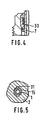
- the end face 13 of the valve body 1 is shaped according to the exemplary embodiments according to FIGS. 1-3 as a conical funnel, while FIG. 4 shows an embodiment with a straight flat surface.
- the valve body 1 is also provided with a stop collar 18, which is designed such that it strikes the stop surface 19 of the coupling bush 2, while the guide part 12 still remains in the bushing bore 20, so that the valve body 1 is securely held and guided .
- the bore 17 of the lower part of the coupling bush 2 is provided with a larger diameter than the remaining part of the bore, so that a cylindrical swirl chamber 16 is formed with the tapered part of the valve 1.
- the swirl chamber 16 can have a conical widening in its lower part facing the fluidic medium, so that the effect mentioned is further increased, i.e. can be further improved.
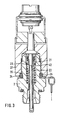
- FIG. 2 shows a measuring coupling which is equipped as a pressure measuring coupling.
- a pressure hose 32 is screwed to the coupling bush 2 with a corresponding union nut.
- a nipple is integrated, with the aid of which the valve body 1 is pushed open, so that the pressure connection is thereby established with the manometer (not shown in more detail).
- the screw-on electrical temperature sensor 21 is provided with a tapered sensor tip 22 which has a conical transition 23.
- An anti-rotation ring 24 is arranged under prestress in the threaded rear rotation 25 of the coupling bush 2 and the recess 26 of the union nut 27, see in particular FIG. 1 but also FIGS. 2 and 3.
- FIG. 5 shows a partial section A - B from FIG. 1.
- the guide gap 15, which is formed between the coupling bush 2 and the valve body 1, is enlarged by notches 31 in such a way that a free flow cross section results, which corresponds to the nominal diameter of the pressure hose 32 to be connected corresponds.
- An O-ring 28 and support ring 29 are arranged in the enlarged bore 30 of the bushing guide part 12.
- the coupling thread 34 is preferably designed as a sawtooth thread.
- the coupling bush 2 is screwed to the union nut 27 and thus secured against contamination.
- a hose nipple which is firmly connected to a pressure hose 32, is screwed onto the coupling bushing 2 and the working pressure is displayed on a manometer (not shown).
- a corresponding measurement can also be carried out with an electrical pressure sensor which is firmly connected to a union nut and a hose nipple.
- the pressure measuring devices mentioned are unscrewed, the temperature sensor 21, see FIG. 3, is inserted with its sensor tip 22 into the valve body 1 and the temperature sensor 21 is screwed to the coupling socket 2 with the aid of a union nut.
- the sensor tip 22 is in direct contact with the fluidic medium and since the valve body 1 is also immersed in the fluidic flow of the system, not only the temperature of the system but also any temperature change can be measured and displayed directly.
- the fluidic system can thus be precisely monitored with regard to its temperature and pressure profile without switching off and without any change or influence by the introduction of the pressure or temperature probes. Since the measuring coupling is always connected to the system, the measurements can be carried out at any time without special preparations.
Abstract
Description
Die Erfindung betrifft eine Meßkupplung für fluidische Systeme zur Erfassung von Arbeitsdrücken oder Temperaturen der fluidischen Medien, bestehend aus einer im eingebauten Zustand unter Leitungsdruck stehenden Kupplungsbuchse, in deren Bohrung ein rederbelastetes und mechanisch betätigbares Rückschlagventil angeordnet ist, welches als ein mit einer zylindrischen Bohrung und einer geschlossenen Bodenfläche versehener Ventilkörper ausgebildet ist, wobei in der Wandung des Ventilkörpers eine radiale Querbohrung oder ein Querschlitz angeordnet ist.The invention relates to a measuring coupling for fluidic systems for detecting working pressures or temperatures of the fluidic media, consisting of a coupling socket in the installed state under line pressure, in the bore of which a red-loaded and mechanically actuated check valve is arranged, which as a with a cylindrical bore and a closed bottom surface provided valve body is formed, wherein a radial transverse bore or a transverse slot is arranged in the wall of the valve body.
Aus der DE-U-1 998 340 ist eine als selbsttätig schließender Nippel ausgebildete Kupplung bekannt, welche die eingangs aufgeführten Merkmale aufweist und als Meßkupplung eingesetzt werden kann. Sie dient zum Beispiel zur Herstellung von Prüf- oder Meßanschlüssen an Druckleitungen, wobei in der Regel die Kupplungsbuchse mit ihrem Einschraubgewinde fest an der Druckleitung eines fluidischen Systems installiert ist. Für die Dauer der Prüf-oder Meßarbeiten wird auf diese Kupplungsbuchse ein als Hohlzapfen ausgebildeter Dichtnippel mittels Überwurfmutter aufgeschraubt, der fest mit einem Schlauch verbunden ist. Die Kupplungen können beispielsweise unter Druck, d.h. ohne die Anlage stillzusetzen, über Meßschläuche mit den entsprechenden Meßgeräten verbunden werden. Bei Anschluß fest installierter Geräte, zum Beispiel Manometer, Manometer-Wahlschalter, elektrische Druckgeber und Druckschalter, können die flexiblen Meßschläuche wie Elektrokabel verlegt werden, so daß eine aufwendige Rohrverlegung entfällt. Mit solchen Meßkupplungen lassen sich daher die effektiven Arbeitsdrücke direkt in der Fluid-Leitung messen, wobei kein Lösen von Entlüftungsschrauben und Rohrverschraubungen erforderlich ist. Solche Kupplungen finden bei den verschiedensten Bauelementen und Regelungen von Fluid-Systemen Verwendung. Nach dem Trennen des Kupplungsanschlusses wird auf die Kupplungsbuchse mit Außengewinde eine Schutzkappe aufgeschraubt, die den Zweck hat, das Eindringen von Schmutz in die Kupplungsbuchse zu verhindern und welche darüberhinaus eine zusätzliche Abdichtfunktion übernimmt, für den Fall, daß ein in die Kupplungsbuchse installiertes Rückschlagventil nicht absolut dicht schließt.From DE-U-1 998 340 a coupling designed as an automatically closing nipple is known, which has the features listed at the beginning and can be used as a measuring coupling. It is used, for example, to make test or measurement connections on pressure lines, with the coupling bush with its screw-in thread usually being permanently installed on the pressure line of a fluidic system. For the duration of the test or measurement work, a sealing nipple designed as a hollow pin is screwed onto this coupling bush by means of a union nut, which is firmly connected to a hose. For example, the couplings can be under pressure, i.e. without shutting down the system, be connected to the corresponding measuring devices via measuring hoses. When permanently installed devices such as pressure gauges, pressure gauge selector switches, electrical pressure transmitters and pressure switches are connected, the flexible measuring hoses such as electrical cables can be laid, so that there is no need to lay pipes. With such measuring couplings, the effective working pressures can therefore be measured directly in the fluid line, with no loosening of ventilation screws and pipe fittings. Such couplings are used in a wide variety of components and controls of fluid systems. After the coupling connection has been disconnected, a protective cap is screwed onto the coupling socket with an external thread, the purpose of which is to prevent dirt from penetrating into the coupling socket and which also has an additional sealing function in the event that a check valve installed in the coupling socket is not absolutely closes tightly.
Für die Messung der Temperaturen des fluidischen Mediums sind gleichwertige Meßkupplungen zur Zeit nicht bekannt. Bisher werden die Temperaturen des fluidischen Mediums entweder mit fest installierten Temperaturfühlern, welche im Flüssigkeitsstrom des Systems liegen, gemessen oder es werden hermetisch dichte Tauchrohre verwendet, in die Temperarturfühler eingebaut sind.Equivalent measuring couplings are currently not known for measuring the temperatures of the fluid medium. So far, the temperatures of the fluid medium have either been measured with permanently installed temperature sensors, which are in the liquid flow of the system, or hermetically sealed immersion tubes have been used, in which temperature sensors are installed.
Die fest installierten Temperaturfühler haben den Nachteil, daß im Servicefall ein Temperatur-Fühlerwechsel in sehr nachteiliger Weise nur bei einer Betriebsstillegung der Anlage durchführbar ist.The permanently installed temperature sensors have the disadvantage that, in the event of service, a temperature sensor change can only be carried out in a very disadvantageous manner when the system is shut down.
Bei Installationen mit Tauchrohren wird in vielen Fällen wegen der Unkenntnis der meßtechnischen Anforderungen nicht die gewünschte Medientemperatur, sondern die Gehäusetemperatur oder ein von der gewünschten Medientemperatur abweichender und damit fehlerhafter Zwischenwert gemessen.In installations with immersion pipes, in many cases, due to the lack of knowledge of the measuring requirements, the desired media temperature is not measured, but rather the housing temperature or an intermediate value that deviates from the desired media temperature and is therefore incorrect.
Demzufolge sind auch Meßkupplungen, an denen beide physikalischen Größen, nämlich Druck und Temperatur, gemessen werden können, nicht bekannt.Accordingly, measuring couplings on which both physical quantities, namely pressure and temperature, can be measured are also not known.
Der vorliegenden Erfindung liegt daher die Aufgabe zugrunde unter Verwendung der an sich bekannten Meßkupplung eine solche Abwandlung derselben vorzuschlagen, daß mit der gleichen Meßkupplung sowohl die Drucke des Systems als auch die Temperaturen des fluidischen Mediums gemessen werden können, wobei während des Betriebes lediglich der Anschluß zum Druckgerät gegen einen Temperaturfühler ausgetauscht wird, während die Meßkupplung mit dem System fest installiert bleibt.The present invention is therefore based on the object using the known measuring coupling to propose such a modification that both the system pressures and the temperatures of the fluidic medium can be measured with the same measuring coupling, only the connection to during operation Pressure device is exchanged for a temperature sensor, while the measuring coupling with the system remains permanently installed.
Das fluidische System soll daher gemäß der Aufgabenstellung während des genannten Austausches nicht drucklos geschaltet werden.The fluidic system should therefore not be switched off according to the task during the exchange mentioned.
Die Lösung dieser Aufgabe besteht gemäß der Erfindung darin, daß der Ventilkörper über das dem fluidischen System zugekehrte Ende der Kupplungsbuchse hinaus verlängert ist, und sich die radiale Querbohrung oder der Querschlitz in der Wandung des Führungsteils des Ventilkörpers befindet, wobei zwischen dem Ventilkörper und der Kupplungsbuchse bis zur radialen Querbohrung oder dem Querschlitz ein Strömungsschlitzkanal ausgebildet ist.This object is achieved according to the invention in that the valve body is extended beyond the end of the coupling sleeve facing the fluidic system, and the radial transverse bore or the transverse slot is located in the wall of the guide part of the valve body, being between the valve body and the coupling sleeve a flow slot channel is formed up to the radial transverse bore or the transverse slot.
Die Querbohrung oder der Querschlitz ermöglichen im Zusammenwirken mit dem Strömungsschlitzkanal den ungehinderten Zufluß des fluidischen Mittels durch den Ventilkörper zum Meßgerät, so daß stets der im System herrschende Druck sich bei Druckmessungen über die radiale Querbohrung oder den Querschlitz fortpflanzt und der wahre Druck gemessen wird.The transverse bore or the transverse slot, in cooperation with the flow slot channel, enables the unimpeded inflow of the fluidic medium through the valve body to the measuring device, so that the pressure prevailing in the system is always propagated when the pressure is measured via the radial transverse bore or the transverse slot and the true pressure is measured.
Ferner wird durch diese Maßnahmen nach der Erfindung erreicht, daß bei Temperaturmessungen im flüssigen Medium ein eventuell in dem Ventilkörper vorhandenes und als Isolator wirkendes Gas verdrängt wird, so daß stets für eine gute Wärmeübertragung an den Temperaturfühler durch direkten Kontakt mit dem flüssigen Medium gesorgt ist, und somit schnelle dynamische Temperaturwechsel erfaßt werden.Furthermore, these measures according to the invention ensure that a gas which may be present in the valve body and acts as an insulator is displaced during temperature measurements in the liquid medium, so that good heat transfer to the temperature sensor is always ensured by direct contact with the liquid medium, and thus rapid dynamic temperature changes can be detected.
Der Ventilkörper weist in vorteilhafter Weise einen die Dichtfläche bildenden, um den Ventilkörper geführten Kragen auf, der gleichzeitig als Anschlag für eine zylindrische Druckfeder dient.The valve body advantageously has a collar which forms the sealing surface and is guided around the valve body and which at the same time serves as a stop for a cylindrical compression spring.
Die Stirnfläche des Ventilkörpers ist als gerade Planfläche oder als Kegeltrichter ausgebildet, so daß je nach Gestaltung des Nippels der Anschlußarmatur eine gute Anpassung gegeben ist.The end face of the valve body is straight Flat surface or designed as a conical funnel, so that depending on the design of the nipple of the connection fitting there is a good adaptation.
In Weiterbildung der Erfindung weist der Ventilkörper einen Anschlagbund auf, welcher derartig ausgebildet ist, daß er an der Anschlagfläche der Kupplungsbuchse anschlägt, während das Führungsteil sich noch in der Buchsenbohrung befindet, womit eine ausreichende und sichere Führung des Ventilkörpers gegeben ist.In a further development of the invention, the valve body has a stop collar, which is designed such that it strikes the stop surface of the coupling bush while the guide part is still in the bushing bore, so that the valve body is adequately and reliably guided.
Die Bohrung des unteren Teils der Kupplungsbuchse ist mit einem größeren Durchmesser versehen als der übrige Teil der Bohrung, derart, daß mit dem verjüngten Teil des Ventils eine zylindrische Wirbelkammer gebildet ist. Das fluidische Medium umspült somit den Ventilkörper über einen relativ großen Teil seiner Länge, wodurch für eine gute Temperaturanpassung bzw. Temperaturübertragung gesorgt wird.The bore of the lower part of the coupling bush is provided with a larger diameter than the remaining part of the bore, in such a way that a cylindrical swirl chamber is formed with the tapered part of the valve. The fluidic medium thus flows around the valve body over a relatively large part of its length, which ensures good temperature adaptation or temperature transmission.
Zur weiteren Verbesserung dieses Effektes ist die Wirbelkammer in ihrem unteren, dem fluidischen Medium zugekehrten Teil mit einer kegelförmigen Erweiterung versehen.To further improve this effect, the lower part of the swirl chamber facing the fluidic medium is provided with a conical extension.
In vorteilhafter Weiterentwicklung der Erfindung weist der aufschraubbare elektrische Temperaturfühler eine verjüngte Fühlerspitze mit einem konischen Übergang auf.In an advantageous further development of the invention, the screw-on electrical temperature sensor has a tapered sensor tip with a conical transition.
Ein Verdrehsicherungsring ist unter Vorspannung in der Gewindehinterdrehung der Kupplungsbuchse und der Aussparung der Überwurfmutter in vorteilhafter Weise angeordnet.An anti-rotation ring is advantageously pre-tensioned in the thread behind the coupling bush and the recess in the union nut.
Ferner ist nach der Erfindung ein Führungsspalt in Verbindung mit in der Kupplungsbuchse befindlichen Kerben vorgesehen, so daß sich ein freier Durchflußquerschnitt ergibt, der der Nennweite des anzuschließenden Druckschlauches entspricht.Furthermore, according to the invention, a guide gap is provided in connection with notches located in the coupling bush, so that there is a free flow cross section which corresponds to the nominal width of the pressure hose to be connected.
In der erweiterten Bohrung des Buchsenführungsteils sind ein O-Ring und ein Stützring angeordnet.An O-ring and a support ring are arranged in the enlarged bore of the bushing guide part.
Das Kupplungsgewinde ist vorzugsweise als Sägezahngewinde ausgebildet.The coupling thread is preferably designed as a saw tooth thread.
Die Erfindung wird anhand der Zeichnung, in der verschiedene Ausführungsbeispiele dargestellt sind, näher erläutert. Hierbei zeigen:
Figur 1 einen Längsschnitt durch die Meßkupplung nach der Erfindung zur Erfassung von Temperaturen und Drücken mit aufgesetzter Stahlschraubkappe;Figur 2 einen Längsschnitt durch die Meßkupplung nach der Erfindung zur Erfassung von Temperaturen und Drücken mit angeschlossenem Hochdruckschlauch für Druckmessungen;Figur 3 einen Längsschnitt durch die Meßkupplung nach der Erfindung zur Erfassung von Temperaturen und Drücken mit angeschlossenem Temperaturfühler für Temperatur und/oder thermostatische Messungen;- Figur 4 einen Ausschnitt aus den Figuren 1 - 3, darstellend einen Teil des Buchsenführungsteils mit dem Ventilkörper, wobei dieser eine gerade Planfläche aufweist; und
- Figur 5 einen Teilschnitt A - B aus
Figur 1.
- Figure 1 shows a longitudinal section through the measuring coupling according to the invention for detecting temperatures and pressures with attached steel screw cap;
- Figure 2 shows a longitudinal section through the measuring coupling according to the invention for detecting temperatures and pressures with connected high pressure hose for pressure measurements;
- 3 shows a longitudinal section through the measuring coupling according to the invention for detecting temperatures and pressures with a connected temperature sensor for temperature and / or thermostatic measurements;
- FIG. 4 shows a detail from FIGS. 1-3, illustrating part of the bushing guide part with the valve body, this having a straight flat surface; and
- FIG. 5 shows a partial section A - B from FIG. 1.
In den Figuren sind gleiche Elemente mit gleichen Bezugszeichen versehen.In the figures, the same elements are provided with the same reference symbols.
Die Figur 1 zeigt eine Meßkupplung im Querschnitt, welche zur Temperatur- oder Druckmessung dient. Die Meßkupplung ist mit einer Überwurfmutter 27 verschraubt, welche für die beabsichtigten Meßzwecke zu lösen ist und welche für den Schutz gegen Verschmutzung sorgt. Darüberhinaus bietet die als Schutzkappe ausgebildete Überwurfmutter noch eine größere Sicherheit gegen Undichtigkeiten des Rückschlagventils, falls solche dort auftreten sollten. Das Rückschlagventil der Meßkupplung ist als ein mit einer zylindrischen Bohrung 3 und einer geschlossenen Bodenfläche 6 versehener Ventilkörper 1 ausgebildet, der über das dem fluidischen System zugekehrte Ende der Kupplungsbuchse 2 hinaus verlängert ist.Figure 1 shows a measuring coupling in cross section, which is used for temperature or pressure measurement. The measuring coupling is screwed to a
In der Wandung des Ventilkörpers 1 befindet sich eine radiale Querbohrung 11 oder ein Querschlitz 33, welcher sich im unteren Teil des Ventilkörper 1 befinden kann, wie aus Figur 6 ersichtlich ist, oder welche auch in der Wandung des Führungsteils 42 des Ventilkörpers 1 angeordnet sein kann, wie aus den Figuren 1 - 3 zu entnehmen ist.In the wall of the
Zwischen dem Ventilkörper 1 und der Kupplungsbuchse 2 ist in diesem Ausführungsbeispiel bis zur radialen Querbohrung 11 oder dem Querschlitz 33 ein Strömungsschlitzkanal 4,41 ausgebildet, so daß das fluidische Medium vom System durch den Strömungsschlitzkanal 4, 41 und durch den Querschlitz 33 oder der Querbohrung 11 in das Innere des Ventilkörpers 1 eindringen kann.In this exemplary embodiment, a
Der Ventilkörper 1 weist einen eine Dichtfläche 8 bildenden und um den Ventilkörper 1 geführten Kragen 7 auf, der gleichzeitig als Anschlag 9 für die zylindrische Druckfeder 10 dient.The
Die Stirnfläche 13 des Ventilkörpers 1 ist gemäß den Ausführungsbeispielen nach den Figuren 1 - 3 als Kegeltrichter geformt, während die Figur 4 eine Ausführung mit gerader Planfläche zeigt.The
Der Ventilkörper 1 ist ferner mit einem Anschlagbund 18 versehen, welcher derartig ausgebildet ist, daß er an der Anschlagfläche 19 der Kupplungsbuchse 2 anschlägt, während das Führungsteil 12 noch in der Buchsenbohrung 20 verbleibt, so daß eine sichere Halterung und Führung des Ventilkörpers 1 gegeben ist.The
Die Bohrung 17 des unteren Teils der Kupplungsbuchse 2 ist mit einem größeren Durchmesser versehen als der übrige Teil der Bohrung, so daß mit dem verjüngten Teil des Ventils 1 eine zylindrische Wirbelkammer 16 gebildet ist. Hierdurch wird der untere Teil des Ventilkörpers 1 von dem Fluid umspült, so daß dadurch der Wärmeübergang begünstigt wird und und somit auch kurzfristige Temperaturänderungen gemessen werden können.The
In einer nicht näher dargestellten Ausführungsform kann die Wirbelkammer 16 in ihrem unteren, dem fluidischen Medium zugekehrten Teil eine kegelförmige Erweiterung aufweisen, so daß der genannte Effekt auf diese Weise noch vergrößert, d.h. weiter verbessert werden kann.In an embodiment not shown in detail, the
Die Figur 2 zeigt eine Meßkupplung, welche als Druckmeßkupplung ausgerüstet ist. Hierbei ist ein Druckschlauch 32 mit einer entsprechenden Überwurfmutter mit der Kupplungsbuchse 2 verschraubt. Mit dem Druckschlauch 32 ist ein Nippel integriert, mit dessen Hilfe der Ventilkörper 1 aufgestoßen wird, so daß dadurch die Druckverbindung mit dem nicht näher dargestellten Manometer hergestellt wird.FIG. 2 shows a measuring coupling which is equipped as a pressure measuring coupling. Here, a
Wie aus der Figur 3 zu entnehmen ist, ist der aufschraubbare elektrische Temperaturfühler 21 mit einer sich verjüngenden Fühlerspitze 22 versehen, welche einen konischen Übergang 23 aufweist.As can be seen from FIG. 3, the screw-on
Ein Verdrehsicherungsring 24 ist unter Vorspannung in der Gewindehinterdrehung 25 der Kupplungsbuchse 2 und der Aussparung 26 der Überwurfmutter 27 angeordnet, siehe hierzu besonders Figur 1 aber auch die Figuren 2 und 3.An
Die Figur 5 zeigt einen Teilschnitt A - B aus Figur 1. Der Führungsspalt 15, der zwischen der Kupplungsbuchse 2 und dem Ventilkörper 1 gebildet ist, ist durch Kerben 31 derart vergrößert, daß sich ein freier Durchflußquerschnitt ergibt, welcher der Nennweite des anzuschließenden Druckschlauches 32 entspricht. In der erweiterten Bohrung 30 des Buchsenführungsteils 12 ist ein O-Ring 28 und Stützring 29 angeordnet.FIG. 5 shows a partial section A - B from FIG. 1. The guide gap 15, which is formed between the
Das Kupplungsgewinde 34 ist vorzugsweise als Sägezahngewinde ausgebildet.The
Sofern keine der Druckprüf- und Meßarbeiten durchgeführt werden ist die Kupplungsbuchse 2 mit der Überwurfmutter 27 verschraubt und damit gegen Verschmutzung gesichert.If none of the pressure test and measurement work is carried out, the
Soll der Druck des Systems gemessen werden, werd ein Schlauchnippel, der mit einem Druckschlauch 32 fest verbunden ist, auf die Kupplungsbuchse 2 aufgeschraubt und der Arbeitsdruck wird an einem nicht näher dargestellten Manometer angezeigt.If the pressure of the system is to be measured, a hose nipple, which is firmly connected to a
Eine entsprechende Messung kann auch mit einem elektrischen Drucksensor durchgeführt werden, der fest mit einer Überwurfmutter und einem Schlauchnippel verbunden ist.A corresponding measurement can also be carried out with an electrical pressure sensor which is firmly connected to a union nut and a hose nipple.
Soll die Temperatur des fluidischen Mediums gemessen werden, werden die genannten Druckmeßgeräte abgeschraubt, der Temperaturfühler 21, siehe hierzu Figur 3, wird mit seiner Fühlerspitze 22 in den Ventilkörper 1 eingeführt und der Temperaturfühler 21 mit Hilfe einer Überwurfmutter mit der Kupplungsbuchse 2 verschraubt. Die Fühlerspitze 22 ist mit dem fluidischen Medium direkt in Verbindung und da ferner der Ventilkörper 1 in den fluidischen Strom des Systems eintaucht, kann nicht nur die Temperatur des Systems, sondern auch jede Temperaturänderung unmittelbar gemessen und angezeigt werden.If the temperature of the fluid medium is to be measured, the pressure measuring devices mentioned are unscrewed, the
Das fluidische System kann somit ohne Abschaltung und ohne jegliche Veränderung oder Beeinflussung durch die Einführung der Druck- oder Temperatursonden hinsichtlich seines Temperatur- und Druckverlaufes exakt überwacht werden. Da die Meßkupplung mit dem System stets verbunden ist, können die Messungen zu jeder Zeit ohne besondere Vorbereitungen durchgeführt werden.The fluidic system can thus be precisely monitored with regard to its temperature and pressure profile without switching off and without any change or influence by the introduction of the pressure or temperature probes. Since the measuring coupling is always connected to the system, the measurements can be carried out at any time without special preparations.
Ferner ist von großem Vorteil, daß auch bereits auf dem Markt befindliche konventionelle Meßkupplungen lediglich durch Austausch des Ventilkörpers für Druck- und Temperaturmessungen verwendet werden können.It is also of great advantage that conventional measuring couplings already on the market can only be used for pressure and temperature measurements by exchanging the valve body.
Claims (12)
Priority Applications (1)
| Application Number | Priority Date | Filing Date | Title |
|---|---|---|---|
| AT84113795T ATE33065T1 (en) | 1983-11-19 | 1984-11-15 | MEASUREMENT COUPLING FOR FLUIDIC SYSTEMS. |
Applications Claiming Priority (2)
| Application Number | Priority Date | Filing Date | Title |
|---|---|---|---|
| DE3341860 | 1983-11-19 | ||
| DE3341860A DE3341860C2 (en) | 1983-11-19 | 1983-11-19 | Measuring coupling for fluid systems |
Publications (3)
| Publication Number | Publication Date |
|---|---|
| EP0142824A2 EP0142824A2 (en) | 1985-05-29 |
| EP0142824A3 EP0142824A3 (en) | 1985-11-13 |
| EP0142824B1 true EP0142824B1 (en) | 1988-03-16 |
Family
ID=6214736
Family Applications (1)
| Application Number | Title | Priority Date | Filing Date |
|---|---|---|---|
| EP19840113795 Expired EP0142824B1 (en) | 1983-11-19 | 1984-11-15 | Measuring connection for fluid systems |
Country Status (5)
| Country | Link |
|---|---|
| US (1) | US4638668A (en) |
| EP (1) | EP0142824B1 (en) |
| JP (1) | JPS60179595A (en) |
| AT (1) | ATE33065T1 (en) |
| DE (1) | DE3341860C2 (en) |
Families Citing this family (38)
| Publication number | Priority date | Publication date | Assignee | Title |
|---|---|---|---|---|
| FR2612600B1 (en) * | 1987-03-16 | 1989-06-09 | Rabusseau Edith | TESTING DEVICE FOR HYDRAULIC CIRCUITS |
| DE3709739A1 (en) * | 1987-03-25 | 1988-10-13 | Heraeus Gmbh W C | SCREW-IN THERMOMETER |
| US4817450A (en) * | 1987-11-30 | 1989-04-04 | Spedco, Inc. | Pressure/temperature test plug assembly |
| US5041087A (en) * | 1988-08-11 | 1991-08-20 | Loo George D H | Needle-less parenteral fluid injector |
| DE3926783A1 (en) * | 1989-08-15 | 1991-03-07 | Hydrotechnik Gmbh | Valve test coupling for fluid systems - consists of valve and hole, with insertion nipple belonging to screw coupling |
| EP0465743A1 (en) * | 1990-07-12 | 1992-01-15 | British Aerospace Public Limited Company | Teach and report probe for a robot arm |
| DE4132690A1 (en) * | 1991-10-01 | 1993-04-08 | Hydrotechnik Gmbh | Valve and measurement coupling for high press. fluid systems - has coupling bush with spring-loaded non-return valve and sealing systems |
| US5324114A (en) * | 1992-01-02 | 1994-06-28 | Waekon Industries, Inc. | Temperature and pressure sensor for cooling systems and other pressurized systems |
| WO1993015323A1 (en) * | 1992-02-01 | 1993-08-05 | Malina, Viktor | High-pressure hydraulic unit |
| DE9315780U1 (en) * | 1992-12-07 | 1993-12-23 | Weh Verbindungstechnik | Coupling nipple |
| US5612499A (en) * | 1995-05-05 | 1997-03-18 | Tdw Delaware, Inc. | Method of inserting a sensor into a pipeline |
| US6015232A (en) * | 1998-06-19 | 2000-01-18 | Fmc Corporation | Constant velocity temperature probe in a product flow line |
| AUPP432898A0 (en) | 1998-06-25 | 1998-07-16 | W.G. Goetz & Sons Limited | Improved check valve arrangement for a diagnostic test point |
| DK1035365T3 (en) | 1999-03-08 | 2004-02-23 | Siegfried Leverberg | Universal Connection |
| US6331176B1 (en) | 1999-03-11 | 2001-12-18 | Advanced Cardiovascular Systems, Inc. | Bleed back control assembly and method |
| SE522010C2 (en) * | 1999-03-17 | 2004-01-07 | Dart Engineering Ag | Device at quick-connect part connectable to systems with pressureable media and such quick-connect part |
| US6220749B1 (en) * | 1999-04-02 | 2001-04-24 | Carrier Corporation | Self-adjusting temperature sensor |
| US6575048B1 (en) * | 1999-11-08 | 2003-06-10 | Parker-Hannifin Corporation | Sensor positioning assembly |
| US6520022B1 (en) * | 2000-11-08 | 2003-02-18 | The Reliable Automatic Sprinkler Co., Inc. | Direct connect pressure tester arrangement |
| DE20103434U1 (en) * | 2001-02-28 | 2001-08-02 | K Dietzel Gmbh Dipl Ing | Device for measuring in or on hose lines |
| DE10232315B4 (en) * | 2001-11-12 | 2009-05-28 | Temperaturmeßtechnik Geraberg GmbH | Combined temperature and pressure sensor and method for the determination of physical characteristics |
| WO2003042593A1 (en) * | 2001-11-15 | 2003-05-22 | Checkfluid Inc. | Probe activated valve system |
| ITMI20020819A1 (en) * | 2002-04-18 | 2003-10-20 | Gambro Lundia Ab | CONNECTION ELEMENT AND CONNECTION DEVICE FOR MEDICAL USE PIPES |
| US6827486B2 (en) * | 2002-11-22 | 2004-12-07 | Welker Engineering Company | Temperature probe and insertion device |
| US7380984B2 (en) * | 2005-03-28 | 2008-06-03 | Tokyo Electron Limited | Process flow thermocouple |
| US7226207B2 (en) * | 2005-09-09 | 2007-06-05 | Feldmeier Robert H | Temperature gauge for use with sanitary conduit |
| US7467891B2 (en) * | 2005-11-29 | 2008-12-23 | Sensata Technologies, Inc. | Sensor arrangement for measuring a pressure and a temperature in a fluid |
| DE102007013818B4 (en) * | 2007-03-22 | 2011-07-14 | Airbus Operations GmbH, 21129 | Aircraft air conditioning system with a measuring connection element |
| DE102009009869B3 (en) * | 2009-02-20 | 2010-07-08 | Temperaturmeßtechnik Geraberg GmbH | Combined temperature and pressure sensor for fluid systems, has base body that is fastened tightly in wall of litigant vessel, where base body has temperature sensor and pressure measuring channel |
| US20110180168A1 (en) * | 2010-01-26 | 2011-07-28 | Jon Terence Stone | True Union Quick-Disconnect Cam-Lock End Connector |
| SE534669C2 (en) * | 2010-03-08 | 2011-11-08 | Tour & Andersson Ab | Measuring needle with check valve function |
| EP2402637A1 (en) * | 2010-07-01 | 2012-01-04 | Alfa Laval Corporate AB | Flow module port fitting |
| US9354121B2 (en) * | 2011-10-13 | 2016-05-31 | Micromold Products, Inc. | Corrosion resistant thermowells with thin wall tips |
| EP2984491A4 (en) | 2013-04-09 | 2017-01-04 | Indian Institute Of Technology Madras | Apparatus for measuring rheological parameters and methods for its operation |
| WO2015028910A1 (en) * | 2013-08-26 | 2015-03-05 | Indian Institute Of Technology Madras | Methods and apparatus for measuring rheological properties of multi-phase fluids |
| US9285252B1 (en) | 2014-10-08 | 2016-03-15 | Ultra Electronics | Sensor and housing suitable for harsh environments |
| DE202015100728U1 (en) | 2015-02-16 | 2015-03-06 | Parker Hannifin Manufacturing Germany GmbH & Co. KG | Measuring coupling with an RFID transponder |
| CN105067183A (en) * | 2015-09-10 | 2015-11-18 | 赵宝林 | Pressure measuring valve |
Family Cites Families (21)
| Publication number | Priority date | Publication date | Assignee | Title |
|---|---|---|---|---|
| CA845400A (en) * | 1970-06-30 | C. Keffer David | Temperature, pressure and sample well | |
| DE312032C (en) * | ||||
| GB706356A (en) * | 1951-09-15 | 1954-03-31 | Booth Walters | Improvements in pressure gauges |
| US2815663A (en) * | 1954-12-13 | 1957-12-10 | Phillips Petroleum Co | Slip probe assembly |
| CH355167A (en) * | 1959-09-08 | 1961-06-30 | Nationale Sa | Valve for filling a liquefied gas container |
| US3115033A (en) * | 1959-12-18 | 1963-12-24 | Kal Equip Company | Compression tester |
| US3188866A (en) * | 1961-03-13 | 1965-06-15 | Honeywell Inc | High speed temperature sensing device |
| US3167733A (en) * | 1964-02-28 | 1965-01-26 | Universal Oil Prod Co | Resistance temperature sensing element |
| DE1998340U (en) * | 1968-03-27 | 1968-12-12 | Sasserath & Co Kg H | SELF-CLOSING NIPPLE |
| CH521657A (en) * | 1970-12-14 | 1972-04-15 | Proton Ag | Measurement device with removable measurement probe |
| US3825222A (en) * | 1972-06-08 | 1974-07-23 | N Petrova | Charging pipe union |
| US3999430A (en) * | 1975-09-02 | 1976-12-28 | G. H. Meiser & Co. | Dial tire pressure gage |
| US4096754A (en) * | 1977-08-26 | 1978-06-27 | E. I. Du Pont De Nemours And Company | Removable probe |
| US4186910A (en) * | 1978-06-08 | 1980-02-05 | Masanobu Higami | Hose connecting mouthpiece |
| US4289027A (en) * | 1979-12-20 | 1981-09-15 | Donald Gleaves | Aircraft fuel tester |
| JPS56122927A (en) * | 1980-03-03 | 1981-09-26 | Kawasaki Heavy Ind Ltd | Air pressure measuring device |
| US4346611A (en) * | 1980-12-19 | 1982-08-31 | Welker Robert H | Insertion regulator for pressurized pipelines |
| US4391289A (en) * | 1981-05-18 | 1983-07-05 | Adams Donald L | Check valve for rod out |
| DE3202422A1 (en) * | 1982-01-26 | 1983-07-28 | Bell-Hermetic-Armaturenwerk GmbH & Co KG, 3509 Spangenberg | Coupling |
| DE8317775U1 (en) * | 1983-06-18 | 1983-10-27 | Apparatebau Spradow GmbH & Co KG, 4800 Bielefeld | SCREW CAP FOR VALVE BODY, IN PARTICULAR MEASURING CONNECTION FOR HYDRAULIC SYSTEMS |
| DE8416303U1 (en) * | 1984-05-26 | 1984-08-23 | Carl Esser KG, 5000 Köln | SHUT-OFF VALVE |
-
1983
- 1983-11-19 DE DE3341860A patent/DE3341860C2/en not_active Expired
-
1984
- 1984-11-15 EP EP19840113795 patent/EP0142824B1/en not_active Expired
- 1984-11-15 AT AT84113795T patent/ATE33065T1/en not_active IP Right Cessation
- 1984-11-19 JP JP59242558A patent/JPS60179595A/en active Pending
- 1984-11-19 US US06/672,640 patent/US4638668A/en not_active Expired - Lifetime
Also Published As
| Publication number | Publication date |
|---|---|
| EP0142824A2 (en) | 1985-05-29 |
| DE3341860A1 (en) | 1985-05-30 |
| ATE33065T1 (en) | 1988-04-15 |
| US4638668A (en) | 1987-01-27 |
| EP0142824A3 (en) | 1985-11-13 |
| DE3341860C2 (en) | 1985-09-19 |
| JPS60179595A (en) | 1985-09-13 |
Similar Documents
| Publication | Publication Date | Title |
|---|---|---|
| EP0142824B1 (en) | Measuring connection for fluid systems | |
| EP0205789B1 (en) | Pressure and temperature sensor for fluidic systems | |
| DE1935989C3 (en) | ||
| DE2756178C2 (en) | ||
| DE2626242C2 (en) | ||
| DE1935989B2 (en) | DIFFERENTIAL PRESSURE FLOW PROBES FOR USE IN A FLOWABLE MEDIUM PIPE | |
| EP0559938B1 (en) | Ultrasonic through put measuring device for liquids | |
| EP0413198B1 (en) | Arrangement for measuring the temperature of a liquid flowing through a conduit | |
| DE3428913A1 (en) | Measuring device for measuring the temperature in a pipeline | |
| DE102019126709A1 (en) | Sensor, measuring tube, measuring device, electromagnetic flow measuring point | |
| DE3508570A1 (en) | Device for inserting sensors into line systems | |
| DE10232315A1 (en) | Combined temperature and pressure sensor for fluid systems has a rotationally symmetric base body, which is detachable for cleaning and maintenance, with central pressure and eccentric temperature measurement channels | |
| CH662404A5 (en) | DEVICE FOR DETERMINING MEASURED SIZES IN PIPELINE SYSTEMS. | |
| DE102004028759B4 (en) | flow sensor | |
| DE1949887C3 (en) | Probe for measuring corrosion in a liquid container | |
| EP0154960A1 (en) | Measuring device for measuring the temperature in a conduit | |
| EP0943901B1 (en) | Fitting for a liquid flowmeter | |
| DE60012926T2 (en) | ARRANGEMENT FOR MEASURING THE PROPERTY OF A LIQUID IN A TUBE | |
| DE19721965A1 (en) | Probe system for gas or liquid flow measurement, e.g. in manufacture of dairy products | |
| EP1193474A1 (en) | Flowmeter arrangement for the magnetic-inductive or capacitive detection of flowrates | |
| DE102009017335A1 (en) | Device for measuring the volume or mass flow of a medium, machine with appropriate device | |
| DE10211533B4 (en) | Hahn block | |
| DE10201335C1 (en) | Probe insertion device for flow medium line uses connection with blocking valve for selective opening of pipeline wall opening | |
| DE4007276C2 (en) | Gas building connection device | |
| DE10227373B4 (en) | Tubular pitot tube |
Legal Events
| Date | Code | Title | Description |
|---|---|---|---|
| PUAI | Public reference made under article 153(3) epc to a published international application that has entered the european phase |
Free format text: ORIGINAL CODE: 0009012 |
|
| AK | Designated contracting states |
Designated state(s): AT BE CH FR GB IT LI NL SE |
|
| TCNL | Nl: translation of patent claims filed | ||
| PUAL | Search report despatched |
Free format text: ORIGINAL CODE: 0009013 |
|
| ITCL | It: translation for ep claims filed |
Representative=s name: UFFICIO TECNICO ING. A. MANNUCCI |
|
| EL | Fr: translation of claims filed | ||
| AK | Designated contracting states |
Designated state(s): AT BE CH FR GB IT LI NL SE |
|
| 17P | Request for examination filed |
Effective date: 19851018 |
|
| 17Q | First examination report despatched |
Effective date: 19870112 |
|
| GRAA | (expected) grant |
Free format text: ORIGINAL CODE: 0009210 |
|
| AK | Designated contracting states |
Kind code of ref document: B1 Designated state(s): AT BE CH FR GB IT LI NL SE |
|
| REF | Corresponds to: |
Ref document number: 33065 Country of ref document: AT Date of ref document: 19880415 Kind code of ref document: T |
|
| PG25 | Lapsed in a contracting state [announced via postgrant information from national office to epo] |
Ref country code: SE Effective date: 19880331 |
|
| ITF | It: translation for a ep patent filed |
Owner name: UFFICIO TECNICO ING. A. MANNUCCI |
|
| GBT | Gb: translation of ep patent filed (gb section 77(6)(a)/1977) | ||
| ET | Fr: translation filed | ||
| PLBE | No opposition filed within time limit |
Free format text: ORIGINAL CODE: 0009261 |
|
| STAA | Information on the status of an ep patent application or granted ep patent |
Free format text: STATUS: NO OPPOSITION FILED WITHIN TIME LIMIT |
|
| 26N | No opposition filed | ||
| PGFP | Annual fee paid to national office [announced via postgrant information from national office to epo] |
Ref country code: AT Payment date: 19891002 Year of fee payment: 6 |
|
| PGFP | Annual fee paid to national office [announced via postgrant information from national office to epo] |
Ref country code: BE Payment date: 19891004 Year of fee payment: 6 |
|
| PGFP | Annual fee paid to national office [announced via postgrant information from national office to epo] |
Ref country code: CH Payment date: 19891124 Year of fee payment: 6 |
|
| PG25 | Lapsed in a contracting state [announced via postgrant information from national office to epo] |
Ref country code: AT Effective date: 19901115 |
|
| PG25 | Lapsed in a contracting state [announced via postgrant information from national office to epo] |
Ref country code: LI Effective date: 19901130 Ref country code: CH Effective date: 19901130 Ref country code: BE Effective date: 19901130 |
|
| BERE | Be: lapsed |
Owner name: HYDROTECHNIK G.M.B.H. Effective date: 19901130 |
|
| REG | Reference to a national code |
Ref country code: CH Ref legal event code: PL |
|
| ITTA | It: last paid annual fee | ||
| PGFP | Annual fee paid to national office [announced via postgrant information from national office to epo] |
Ref country code: GB Payment date: 19971111 Year of fee payment: 14 |
|
| PGFP | Annual fee paid to national office [announced via postgrant information from national office to epo] |
Ref country code: NL Payment date: 19971130 Year of fee payment: 14 |
|
| PG25 | Lapsed in a contracting state [announced via postgrant information from national office to epo] |
Ref country code: GB Free format text: LAPSE BECAUSE OF NON-PAYMENT OF DUE FEES Effective date: 19981115 |
|
| PG25 | Lapsed in a contracting state [announced via postgrant information from national office to epo] |
Ref country code: NL Free format text: LAPSE BECAUSE OF NON-PAYMENT OF DUE FEES Effective date: 19990601 |
|
| GBPC | Gb: european patent ceased through non-payment of renewal fee |
Effective date: 19981115 |
|
| NLV4 | Nl: lapsed or anulled due to non-payment of the annual fee |
Effective date: 19990601 |
|
| PGFP | Annual fee paid to national office [announced via postgrant information from national office to epo] |
Ref country code: FR Payment date: 20031029 Year of fee payment: 20 |