EP0142616B1 - Method and apparatus for editing and for replay of digital audio data recorded on a magnetic tape - Google Patents
Method and apparatus for editing and for replay of digital audio data recorded on a magnetic tape Download PDFInfo
- Publication number
- EP0142616B1 EP0142616B1 EP84108694A EP84108694A EP0142616B1 EP 0142616 B1 EP0142616 B1 EP 0142616B1 EP 84108694 A EP84108694 A EP 84108694A EP 84108694 A EP84108694 A EP 84108694A EP 0142616 B1 EP0142616 B1 EP 0142616B1
- Authority
- EP
- European Patent Office
- Prior art keywords
- tape
- edit
- store
- point
- coded information
- Prior art date
- Legal status (The legal status is an assumption and is not a legal conclusion. Google has not performed a legal analysis and makes no representation as to the accuracy of the status listed.)
- Expired
Links
- 238000000034 method Methods 0.000 title claims description 39
- 239000000463 material Substances 0.000 claims abstract description 41
- 125000004122 cyclic group Chemical group 0.000 claims description 7
- 238000005070 sampling Methods 0.000 abstract description 7
- 230000000694 effects Effects 0.000 description 6
- 238000010586 diagram Methods 0.000 description 5
- 238000004519 manufacturing process Methods 0.000 description 5
- 230000006870 function Effects 0.000 description 3
- 230000007246 mechanism Effects 0.000 description 3
- 230000005540 biological transmission Effects 0.000 description 2
- 238000012937 correction Methods 0.000 description 2
- 230000009191 jumping Effects 0.000 description 2
- 238000011161 development Methods 0.000 description 1
- 230000018109 developmental process Effects 0.000 description 1
- 238000010348 incorporation Methods 0.000 description 1
- 238000012545 processing Methods 0.000 description 1
- 239000007787 solid Substances 0.000 description 1
Images

Classifications
-
- G—PHYSICS
- G11—INFORMATION STORAGE
- G11B—INFORMATION STORAGE BASED ON RELATIVE MOVEMENT BETWEEN RECORD CARRIER AND TRANSDUCER
- G11B27/00—Editing; Indexing; Addressing; Timing or synchronising; Monitoring; Measuring tape travel
- G11B27/02—Editing, e.g. varying the order of information signals recorded on, or reproduced from, record carriers
- G11B27/031—Electronic editing of digitised analogue information signals, e.g. audio or video signals
- G11B27/036—Insert-editing
-
- G—PHYSICS
- G11—INFORMATION STORAGE
- G11B—INFORMATION STORAGE BASED ON RELATIVE MOVEMENT BETWEEN RECORD CARRIER AND TRANSDUCER
- G11B20/00—Signal processing not specific to the method of recording or reproducing; Circuits therefor
- G11B20/10—Digital recording or reproducing
- G11B20/10527—Audio or video recording; Data buffering arrangements
-
- G—PHYSICS
- G11—INFORMATION STORAGE
- G11B—INFORMATION STORAGE BASED ON RELATIVE MOVEMENT BETWEEN RECORD CARRIER AND TRANSDUCER
- G11B27/00—Editing; Indexing; Addressing; Timing or synchronising; Monitoring; Measuring tape travel
- G11B27/10—Indexing; Addressing; Timing or synchronising; Measuring tape travel
- G11B27/19—Indexing; Addressing; Timing or synchronising; Measuring tape travel by using information detectable on the record carrier
- G11B27/28—Indexing; Addressing; Timing or synchronising; Measuring tape travel by using information detectable on the record carrier by using information signals recorded by the same method as the main recording
-
- G—PHYSICS
- G11—INFORMATION STORAGE
- G11B—INFORMATION STORAGE BASED ON RELATIVE MOVEMENT BETWEEN RECORD CARRIER AND TRANSDUCER
- G11B20/00—Signal processing not specific to the method of recording or reproducing; Circuits therefor
- G11B20/10—Digital recording or reproducing
- G11B20/10527—Audio or video recording; Data buffering arrangements
- G11B2020/10537—Audio or video recording
- G11B2020/10592—Audio or video recording specifically adapted for recording or reproducing multichannel signals
-
- G—PHYSICS
- G11—INFORMATION STORAGE
- G11B—INFORMATION STORAGE BASED ON RELATIVE MOVEMENT BETWEEN RECORD CARRIER AND TRANSDUCER
- G11B2220/00—Record carriers by type
- G11B2220/90—Tape-like record carriers
-
- G—PHYSICS
- G11—INFORMATION STORAGE
- G11B—INFORMATION STORAGE BASED ON RELATIVE MOVEMENT BETWEEN RECORD CARRIER AND TRANSDUCER
- G11B2220/00—Record carriers by type
- G11B2220/90—Tape-like record carriers
- G11B2220/91—Helical scan format, wherein tracks are slightly tilted with respect to tape direction, e.g. VHS, DAT, DVC, AIT or exabyte
- G11B2220/913—Digital audio tape [DAT] format
-
- G—PHYSICS
- G11—INFORMATION STORAGE
- G11B—INFORMATION STORAGE BASED ON RELATIVE MOVEMENT BETWEEN RECORD CARRIER AND TRANSDUCER
- G11B27/00—Editing; Indexing; Addressing; Timing or synchronising; Monitoring; Measuring tape travel
- G11B27/02—Editing, e.g. varying the order of information signals recorded on, or reproduced from, record carriers
- G11B27/031—Electronic editing of digitised analogue information signals, e.g. audio or video signals
- G11B27/032—Electronic editing of digitised analogue information signals, e.g. audio or video signals on tapes
Definitions
- This invention relates to a method for editing interleaved digital audio data recorded on a magnetic tape and an apparatus for editing and replay of digital audio data.
- Different types of editing may be executed in audio editing. For example if wanted passages of a speech or music from different takes or sections of the master recording are to be linked, then it is assembly edits which are involved. Similarly, the final mixes of the various items of an "ablum" must be arranged in the desired sequence with the proper amount of lead-in between each selection. Condensing edits are used when it is necessary to reduce playing time or remove quiet passages, remove sentences, words etc. from a master recording. For insert edits, portions of one or more existing channels are altered by inserting fresh material from the studio.
- the edited tape has one or more edits in it where an edit is defined as the place where the material changes from a lead-in tape or material to a lead-out tape or material.
- an edit is defined as the place where the material changes from a lead-in tape or material to a lead-out tape or material.
- an actual splice point if the edit has been effected by cutting and splicing.
- the corresponding bits are- organised and arranged in a particular format.
- Choice of an efficient format is essential for economical transmission and recording of data.
- Editing of digital audio data recorded on a magnetic tape as it is actually done is not entirely satisfactory in professional use. This is because the editing of such data is limited by the capabilities of the error correction devices used. These error correction devices are capable of replacing lost bits or lost data on the basis of the redundant information previously added to the digital data on the tape. More serious errors which are beyond the correcting capability of the error protecting check code are concealed by approximating the missing samples from adjacent error free ones.
- an interleaving process is applied to the data on recording. This consists in dispersing the digital samples along the tape before recording and in re-ordering them on play-back or replay. In this way, consecutive data are stored far apart, and the bursts of errors due to drop-outs caused by the cutting of the tape are distributed more evenly among digital samples.
- the object of the present invention is therefore to avoid these drawbacks and to provide a method for performing edits with a perfect professional quality as well as an apparatus for carrying out this method.
- a method of editing digital audio data on a magnetic tape characterised in that the edited tape is provided at each edit with an actual or notional splice point and with coded information identifying a first edit point and a second edit point related to said splice point in such a way that interleaved digital audio data is replayed from the tape up to the splice point and starting again up from the splice point and that deinterleaved digital audio data is produced up to the first edit point and starting again from the second edit point.
- the invention makes perfect edits possible.
- the unwanted material recorded in the space between the edit points can be sufficient to ensure proper operation of the conventional error protection mechanism on replay. What unwanted material is recorded will depend upon the nature of the protection mechanism but preferably unwanted lead-in material is recorded in the said space from the first edit point up to an actual or notional splice point and unwanted lead-out material is recorded in the said space from the splice point up to the second edit point.
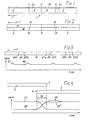
- Figure 1 shows an edit 1 on two tapes 2 and 3, namely a lead-in tape 2 and a lead-out tape 3.
- the two tapes 2, 3 are joined together in a splice point 4.
- Figure 1 therefore shows a so called tape-splice edit as an example.
- Other types of edits may be handled much the same way except that there is no physical cutting-point 4.
- the actual or notional splice point lies between two edit points 5 and 6.
- Figure 1 is based on the assumption that the tapes 2, 3 move according to the direction of an arrow 7 past a replay head.
- the distance between the splice point 4 and the edit points 5 or 6 has to be sufficient that damage resulting from the splice does not impede the perfect reconstruction of the digital-audio data up to the first edit point 5 and beyond the second edit point-6.
- Figure 2 shows tapes 2 and 3 as shown in Figure 1. These tapes 2 and 3 join in the same splice point 4. In this example the tapes 2 and 3 are recorded with two different tracks 11 and 12, so we have to deal now with four different edit points as numbered 13 to 16. These can all be identified corresponding coded information.
- Figure 3 shows a part of a tape 19 containing three edits 20, 21 and 22 with first edit points 20a, 21 a and 22a and second edit points 20b, 21 b and 22b.
- the diagram associated with the tape 19 shows the relation of the speed of the tape 19 to time. Variations of tape speed during the replay operation and the reasons will be explained more in detail later on.
- Figure 4 also shows associated replay gain profiles which define the gain for the replayed material and may be used for various purposes.
- the example illustrated is for a cross fade.
- the time scale of Fig. 4 is greatly compressed relative to Fig. 1.
- the gain profile 27 falls off smoothly up to the point 5 while, for the lead-out material, the gain profile 28 rises from the point 6.
- the gain profiles may compensate to allow the ear time to adopt to the new level.
- the tape 3 has a relatively low level, a temporary enhancement of gain is appropriate, as indicated by the part 29 of the profile 28.
- the opposite case of a temporary lowering of gain is shown in broken lines at 29'.
- These profiles may be established by further coded information recorded on the tape.
- the replay machine may be equipped to respond to such coded information by following pre-programmed gain profiles.
- the profiles are preferably defined more fully by a succession of codes. This allows more flexibility as the editor can adapt the profile to suit a given edit.
- Figure 5 is a block diagram of an apparatus for editing and replaying edited tape material.
- the apparatus comprises a tape machine of known form, equipped to record and replay digital audio data. Since such machines are well known, the tape machine itself is not shown in detail.
- Figure 5 shows only the magnetic tape 31 a record/replay head 32 and a block 10 representing the tape speed control unit which comprises a capstan and motor in a closed loop servo system which can derive a feedback signal representing tape speed either from a clock track on the tape itself or from a tachometer coupled to the capstan.
- a read-write head 32 is shown for-simplicity, it will be appreciated that separate record and replay heads will normally be employed.
- the head or heads are coupled by way of a conventional encoder/decoder 33, which implements whatever format is employed for the bits of the digital data, to a RAM store 34 which can comprise solid state RAM chips operating with fixed timing locked to the audio sampling rate and including several write cycles per sampling interval for accommodating fluctuating incoming data rates, as well as several read cycles for ease of processing, especially in effecting cross-fades.
- a RAM store 34 which can comprise solid state RAM chips operating with fixed timing locked to the audio sampling rate and including several write cycles per sampling interval for accommodating fluctuating incoming data rates, as well as several read cycles for ease of processing, especially in effecting cross-fades.
- Electronic stores of this kind are well known in current digital audio technology.
- the store 34 acts as a buffer between the magnetic tape 31 and conventional input/output electronics 37 which operate strictly at the audio sampling rate, determined by a clock source 50.
- a combining unit and gain control 36 may be interposed between lines 35, 35' from the store and the input/output electronics 37, for a purpose explained below.
- Digital samples are written into the store 34 under control of a write address generator 38 and a read out under -control of a read address generator 39.
- a control unit 51 determines the mode of operation of the apparatus.
- the store 34 writes data from the input/ output electronics 37 and reads data out to the tape head 32.
- the write address generator 38 runs at the audio sampling rate established by the clock source 50 and steps cyclically through the addresses of the store.
- the read address generator 39 operates in the same way but it is clocked at a rate corresponding to instantaneous tape speed under control of a signal representing this speed and provided from the unit 10 to the unit 51 on a line 52.
- control unit 51 switches the store 31 to write from the tape head 32 and to read out to the input/output electronics 37.
- the write address generator 38 is now clocked in dependence upon tape speed whereas the read address generator 39 is clocked at the audio sampling rate.
- a comparing unit 40 is connected to the two address generators 38 and 39 and monitors the degree of filling of the store on the basis of the difference between the write and read addresses. In the preferred mode of operation, the degree of filling of the store is maintained substantially constant and, to this end, the comparing unit 40 provides a signal on a line 41 to the tape speed control unit 10.
- the mode control unit 51 also switches the operation of the unit 10 so that, during recording, if the store 34 gets too full, the tape is speeded up so as to withdraw additional samples from the store whereas, during replay, if the store gets too full, the tape is slowed down to reduce the rate at which samples are written into the store.
- a record/replay head 42 This may be a separate head as shown or be part of a multi-track record/ replay head 32, or separate multi-track record and replay heads.
- the head 42 is connected to a code processor 43 which can emit control codes during recording and receive and act upon control codes during replay.
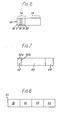
- the data structure may consist of a data block 65 divided into a plurality of labels 66, as shown in Fig. 8.
- the block may have,.a total length of 192 bits, divided into four labels of 48 bits each.
- Fig. 6 shows a possible label format.
- the label is divided into an identification field 54 and a parameter field 55 which may consist of 16 bits and 32 bits respectively.
- the identification field 54 is composed of a label class field 56 of 4 bits, a security level and count down field 57 of 3 bits, a label frame synchronisation field 58 of 1 bit, a priority level field 59 of 2 bits and an instruction field 60 of 6 bits, for example.
- Such a format permits considerable flexibility in defining and responding to control codes but for the purposes of understanding the present invention it is sufficient to consider the instruction field 60 as including an instruction which identifies the control operation in question.
- two instructions may respectively define a first edit point 5 and a second edit point 6.
- Some instructions will additionally require parameter values which are placed in the field 55.
- one instruction may specify a gain setting operation, the value of the gain being included in the parameter field 55.
- Fig. 7 shows one possibility.
- the total label size is increased to 72 bits and each label is made-up of an 8 bit preamble field 62, the 48 bit label field 66 itself and a 16 bit cyclic redundancy check field 64.
- the preamble field 62 may consist of a 6 bit HDM-1 violating preamble word 62a and a 2 bit overwrite number field 62b.
- the labels can be recorded on two source tapes before they are spliced or electronically combined to form the edited tape. Alternatively the labels can be recorded on the edited tape after production thereof. If the editing is performed electronically, it is possible to record the labels during the production of the edited tape from the two source tapes.
- the actual or notional cutting point 4 is selected to be spaced sufficiently after the first edit point 5 and sufficiently in advance of the second edit point 6 to incorporate the unwanted material 8, 9 (Fig. 1) which will ensure efficient operation of the conventional error protection mechanisms.
- the code processor 43 detects and responds to the labels replayed by the head 42.
- the code processor in turn controls operation of the address generators by way of the control unit 51.
- the control unit 51 stops the write address generator 38.
- the write address generator 38 is restarted. The unwanted material between the two edit points is therefore never written into the store 34. Since the read address generator 39 continues to run in an uninterrupted and regular fashion, the replayed material simply jumps from the edit point 5 to the edit point 6.
- control unit 51 monitors the time between the first and second edit points as signaled by the code processor 43 and jumps the read address generator 39 by a corresponding amount when this generator reaches the address corresponding to the first edit point 5.
- This technique is pefectly feasible but more complex to implement than the preferred technique of stopping the write address generator 38 between the two edit point.
- a store 34 which has sufficient capacity to allow for the maximum number of edits which will be encountered in practice.
- the store must be adequately precharged at the beginning of replay.
- a preferred technique is to make up the contents of the store 34 after each edit and this is achieved automatically in the illustrated embodiment by the operation of the comparing unit 40 acting on the tape speed control unit 10. Following every edit, the store contents fall and the signal on the line 41 causes the tape to speed up until the store has been replenished. This is illustrated in Fig. 3 where the tape speed is normally constant but exhibits a burst 48 of additional speed after each edit.
- the code processor 43 also detects labels defining gain values and can control replay gain via the combining unit 36 which contains, in respect of each channel 35, 35', a register for storing a gain value (and which is updated whenever a label specifies a new gain value) and a digital multiplier which multiplies the digital samples by the gain value.
- the code processor 43 may be a suitably programmed microprocessor which can incorporate the control unit 51 with an output port to effect the necessary control of the store 34, the address generators 38 and 39 and the tape speed control unit 10, as well as an input port for the tape speed signal on the line 52.
- the combining unit 36 accepts one or more outputs through the lines 35, 35' from the store 35 and combines the outputs into a single signal fed to the input/output electronics 37. This is effected in the region of overlap 30 (Fig. 4) by having two read-outs per sampling interval effected by two read address generators 39 and 39' of which one reads ahead of the other by an amount corresponding to the overlap 30.
- the store 34 must obviously have sufficient capacity to allow this.
- the alternative samples are processed in their respective digital multipliers so that the gain profiles pertaining to each are implemented. The samples are then added in pairs to produce the output samples which pass at sample rate to the electronics 37.
- the method according to the invention allows edit points to be shifted slightly even after the tape has been cut and spliced or electronically edited.
- the tape In the immediate vicinity of the splice point 4 (Fig. 1), the tape is damaged and the data is corrupted.
- the positions of the edit points 5 and 6 have been chosen with some margin for error, the data immediately to the right of the point 5 and to the left of point 6 in Fig. 1 are likely still to be valid even after the splice has been made.
- data to the left of the point 5 and to the right of the point 6 are certainly valid, since they are far removed from the splice point 4.
- the original positions of the edit points 5 and 6 are defined by the coded information put on the separate track 18 on the tape (or interleaved with the audio data).
- the edit points may be redefined.
- the edit is shown shifted slightly to the right with the new edit points defined at 5a and 6a. In this operation, only the coded information is altered; the original audio data itself remains unchanged. By means of such operations, it is possible to correct slight errors in the original determination of the points 5 and 6 and improve the audible effect of the edit.
- the apparatus can consist essentially of a conventional tape drive and audio electronics for recording only supplemented by a coding device for writing labels on to the dedicated track 18.
- apparatus for tape replay requires the facilities of Figure 5 in order to make it possible to eliminate the unwanted material between the edit points 5 and 6.
- the coded information relating to edits of a tape having a plurality of audio channels or tracks is to be handled by a single dedicated track 18, then well known multiplexing techniques may be used.
- the control information for each audio track may be time division multiplexed to the audio track itself.
Landscapes
- Engineering & Computer Science (AREA)
- Multimedia (AREA)
- Signal Processing (AREA)
- Management Or Editing Of Information On Record Carriers (AREA)
- Signal Processing For Digital Recording And Reproducing (AREA)
Abstract
Description
- This invention relates to a method for editing interleaved digital audio data recorded on a magnetic tape and an apparatus for editing and replay of digital audio data.
- Different types of editing may be executed in audio editing. For example if wanted passages of a speech or music from different takes or sections of the master recording are to be linked, then it is assembly edits which are involved. Similarly, the final mixes of the various items of an "ablum" must be arranged in the desired sequence with the proper amount of lead-in between each selection. Condensing edits are used when it is necessary to reduce playing time or remove quiet passages, remove sentences, words etc. from a master recording. For insert edits, portions of one or more existing channels are altered by inserting fresh material from the studio.
- Regardless of the type of editing involved the edited tape has one or more edits in it where an edit is defined as the place where the material changes from a lead-in tape or material to a lead-out tape or material. At each edit there is an actual splice point if the edit has been effected by cutting and splicing. There is a notional splice point if the editing has actually been performed electronically.
- In United States Patent No. 4,234,896 a method of editing digital audio data recorded on a plurality of tracks using actual splice points is disclosed. This method uses sensor means for sensing a spliced portion of the record medium to produce a splice sensing signal. This signal has the effect of suspending the writing of the data in a memory. This way data damaged by the splice are not replayed.
- For transmission and recording of a message or of digitized audio information, the corresponding bits are- organised and arranged in a particular format. Choice of an efficient format is essential for economical transmission and recording of data. In particular it is necessary to include certain errror checking/correcting facilities (error protection) such as the incorporation of cyclic redundancy check codes.
- Editing of digital audio data recorded on a magnetic tape as it is actually done is not entirely satisfactory in professional use. This is because the editing of such data is limited by the capabilities of the error correction devices used. These error correction devices are capable of replacing lost bits or lost data on the basis of the redundant information previously added to the digital data on the tape. More serious errors which are beyond the correcting capability of the error protecting check code are concealed by approximating the missing samples from adjacent error free ones.
- In order to reduce further the effects of drop-outs, especially drop-outs due to editing, or cutting of the tape, an interleaving process is applied to the data on recording. This consists in dispersing the digital samples along the tape before recording and in re-ordering them on play-back or replay. In this way, consecutive data are stored far apart, and the bursts of errors due to drop-outs caused by the cutting of the tape are distributed more evenly among digital samples.
- Unfortunately these measures do not suffice to enable the professional user to perform all kinds of edits perfectly. In most of the edits, too many samples of the digital audio data are lost.
- The same is true for the method proposed in United States Patent No. 4,234,896. This method can rot be used when interleaved data are to be edited because too many data would be lost at the splice points.
- The object of the present invention is therefore to avoid these drawbacks and to provide a method for performing edits with a perfect professional quality as well as an apparatus for carrying out this method.
- According to the present invention there is provided a method of editing digital audio data on a magnetic tape characterised in that the edited tape is provided at each edit with an actual or notional splice point and with coded information identifying a first edit point and a second edit point related to said splice point in such a way that interleaved digital audio data is replayed from the tape up to the splice point and starting again up from the splice point and that deinterleaved digital audio data is produced up to the first edit point and starting again from the second edit point.
- The invention makes perfect edits possible. On the one hand, the unwanted material recorded in the space between the edit points can be sufficient to ensure proper operation of the conventional error protection mechanism on replay. What unwanted material is recorded will depend upon the nature of the protection mechanism but preferably unwanted lead-in material is recorded in the said space from the first edit point up to an actual or notional splice point and unwanted lead-out material is recorded in the said space from the splice point up to the second edit point.
- Although the unwanted material performs this useful function it is eliminated in the method of replaying the tape, effectively by jumping from the first edit point to the second when reading data out of the buffer store. Such a jump may be implemented by jumping a read-out address or by preventing write-in during the space between the first and second edit points. The coded information which enables this to be done may be on a separate dedicated track or be interleaved with the audio data. Other coded information may be used to define a replay gain profile, e.g. in producing cross-fade edits.
- The apparatus according to the invention and advantageous developments of the method and apparatus are defined in the appended claims.
- The invention will be described in more detail, by way of example, with reference to the accompanying drawings, in which:
- Figure 1 shows an example of an edit on a magnetic tape loaded with digital audio data,
- Figure 2 shows an edit as in Figure 1 but for two different data channels on the tape,
- Figure 3 shows a tape with a plurality of edits associated with a diagram showing the speed of the tape during replay,
- Figure 4 shows a piece of lead-in and a piece of lead-out material following replay as well as a diagram showing gain-profiles for both tape materials,
- Figure 5 is a block diagram of apparatus embodying the invention, and
- Figures 6, 7 and 8 show structures for accommodating data on a tape.
- Figure 1 shows an edit 1 on two
tapes tape 2 and a lead-outtape 3. The twotapes splice point 4. Figure 1 therefore shows a so called tape-splice edit as an example. Other types of edits may be handled much the same way except that there is no physical cutting-point 4. The actual or notional splice point lies between twoedit points 5 and 6. - Figure 1 is based on the assumption that the
tapes arrow 7 past a replay head. The distance between thesplice point 4 and theedit points 5 or 6 has to be sufficient that damage resulting from the splice does not impede the perfect reconstruction of the digital-audio data up to thefirst edit point 5 and beyond the second edit point-6. - Areas 8 and 9 between the
edit points 5 and 6, i.e. between theedit points 5 and 6 respectively and thesplice 4, contain data which are immaterial to the replaying process. This data is corrupted by thesplice 4 and is of no consequence. As a result the replay machine has to ignore data contained betweenedit point 5 and the edit point 6 during replay. In practice the data to be ignored may account for 100 milliseconds of unwanted audio-time. Although it is ignored, it allows the error protection devices of the replay machine to function correctly during replay. These devices are not shown but act in conventional manner. To enable replay machine to "jump" between twoedit points 5 and 6, thetapes edit points 5 and 6. This coded information may be provided according to any suitable technique. For example the coded information may be on a separatededicated track 18 or it may be interleaved with the digital audio data. - Figure 2 shows
tapes tapes same splice point 4. In this example thetapes different tracks - Figure 3 shows a part of a tape 19 containing three
edits 20, 21 and 22 with first edit points 20a, 21 a and 22a and second edit points 20b, 21 b and 22b. The diagram associated with the tape 19, shows the relation of the speed of the tape 19 to time. Variations of tape speed during the replay operation and the reasons will be explained more in detail later on. - When the tape of Fig. 1 is replayed, the material may appear with the editing points 5 and 6 coincident because the unwanted material has been eliminated. However it is also possible to create an overlap for the purpose of a cross-fade for example. This is illustrated in Fig. 4 where the lead-in material is read out of the store up to point 5 while lead-out material is read out from point 6 commencing before
point 5 is reached in the lead-in material. There is thus a period ofoverlap 30 during which two read address generators have to be operating in time interleaved manner with combination of read-out samples, as will be described below. - Figure 4 also shows associated replay gain profiles which define the gain for the replayed material and may be used for various purposes. The example illustrated is for a cross fade. The time scale of Fig. 4 is greatly compressed relative to Fig. 1. For the lead-in material, the
gain profile 27 falls off smoothly up to thepoint 5 while, for the lead-out material, thegain profile 28 rises from the point 6. If the recording levels of thetapes tape 3 has a relatively low level, a temporary enhancement of gain is appropriate, as indicated by thepart 29 of theprofile 28. The opposite case of a temporary lowering of gain is shown in broken lines at 29'. These profiles may be established by further coded information recorded on the tape. The replay machine may be equipped to respond to such coded information by following pre-programmed gain profiles. However, the profiles are preferably defined more fully by a succession of codes. This allows more flexibility as the editor can adapt the profile to suit a given edit. - Figure 5 is a block diagram of an apparatus for editing and replaying edited tape material. The apparatus comprises a tape machine of known form, equipped to record and replay digital audio data. Since such machines are well known, the tape machine itself is not shown in detail. Figure 5 shows only the magnetic tape 31 a record/
replay head 32 and ablock 10 representing the tape speed control unit which comprises a capstan and motor in a closed loop servo system which can derive a feedback signal representing tape speed either from a clock track on the tape itself or from a tachometer coupled to the capstan. Although a read-write head 32 is shown for-simplicity, it will be appreciated that separate record and replay heads will normally be employed. - The head or heads are coupled by way of a conventional encoder/
decoder 33, which implements whatever format is employed for the bits of the digital data, to aRAM store 34 which can comprise solid state RAM chips operating with fixed timing locked to the audio sampling rate and including several write cycles per sampling interval for accommodating fluctuating incoming data rates, as well as several read cycles for ease of processing, especially in effecting cross-fades. Electronic stores of this kind are well known in current digital audio technology. - The
store 34 acts as a buffer between themagnetic tape 31 and conventional input/output electronics 37 which operate strictly at the audio sampling rate, determined by aclock source 50. A combining unit and gaincontrol 36 may be interposed betweenlines 35, 35' from the store and the input/output electronics 37, for a purpose explained below. - Digital samples are written into the
store 34 under control of awrite address generator 38 and a read out under -control of aread address generator 39. Acontrol unit 51 determines the mode of operation of the apparatus. For a recording operation, as in producing an edited tape, thestore 34 writes data from the input/output electronics 37 and reads data out to thetape head 32. Thewrite address generator 38 runs at the audio sampling rate established by theclock source 50 and steps cyclically through the addresses of the store. Theread address generator 39 operates in the same way but it is clocked at a rate corresponding to instantaneous tape speed under control of a signal representing this speed and provided from theunit 10 to theunit 51 on aline 52. Conversely, for a replay operation, thecontrol unit 51 switches thestore 31 to write from thetape head 32 and to read out to the input/output electronics 37. Thewrite address generator 38 is now clocked in dependence upon tape speed whereas theread address generator 39 is clocked at the audio sampling rate. - By clocking the
read address generator 38 in dependence upon tape speed during recording, a uniform spacing of the recorded samples on thetape 31 is assured. On the other hand, by clocking thewrite address generator 38 in accordance with tape speed during replay it is ensured that the samples recovered from thetape 31 are correctly entered into thestore 34. - A comparing
unit 40 is connected to the twoaddress generators unit 40 provides a signal on aline 41 to the tapespeed control unit 10. Themode control unit 51 also switches the operation of theunit 10 so that, during recording, if thestore 34 gets too full, the tape is speeded up so as to withdraw additional samples from the store whereas, during replay, if the store gets too full, the tape is slowed down to reduce the rate at which samples are written into the store. - During the production of an edited tape it is necessary to record coded information defining the edit points 5 and 6 and possibly also the gain profile (Fig. 4). In the embodiment of Fig. 5 it is assumed that the coded information is recorded on a separate dedicated track 18 (Fig. 1) by way of a record/
replay head 42. This may be a separate head as shown or be part of a multi-track record/replay head 32, or separate multi-track record and replay heads. Thehead 42 is connected to a code processor 43 which can emit control codes during recording and receive and act upon control codes during replay. Before considering operation of the apparatus during recording and replay, some possible data structures for the control codes may be explained. The data structure may consist of adata block 65 divided into a plurality oflabels 66, as shown in Fig. 8. For example, the block may have,.a total length of 192 bits, divided into four labels of 48 bits each. Fig. 6 shows a possible label format. The label is divided into anidentification field 54 and aparameter field 55 which may consist of 16 bits and 32 bits respectively. Theidentification field 54 is composed of alabel class field 56 of 4 bits, a security level and count downfield 57 of 3 bits, a labelframe synchronisation field 58 of 1 bit, apriority level field 59 of 2 bits and aninstruction field 60 of 6 bits, for example. Such a format permits considerable flexibility in defining and responding to control codes but for the purposes of understanding the present invention it is sufficient to consider theinstruction field 60 as including an instruction which identifies the control operation in question. For example two instructions may respectively define afirst edit point 5 and a second edit point 6. Some instructions will additionally require parameter values which are placed in thefield 55. For example, in order to establish a desired replay gain profile, one instruction may specify a gain setting operation, the value of the gain being included in theparameter field 55. - Known techniques may be employed to ensure adequate error protection for the labels and Fig. 7 shows one possibility. The total label size is increased to 72 bits and each label is made-up of an 8
bit preamble field 62, the 48bit label field 66 itself and a 16 bit cyclicredundancy check field 64. Thepreamble field 62 may consist of a 6 bit HDM-1 violatingpreamble word 62a and a 2 bit overwritenumber field 62b. - Further information on these matters may be found in our copending application of even data EP-A-0 142 626.
- Consider now operation during production of an edited tape. The editor has to select his
first edit point 5 and his second edit point 6 on the lead-in material and the lead-out material respectively. This may be done in conventional manner as in the normal editing technique where the two edit points actually define the splice point for the two tapes. Having selected the edit points 5 and 6, the corresponding identifying codes have to be recorded on thededicated track 18 and this is readily achieved by way of the code processor 43 under control of akeyboard 44, for example. The editor keys in an instruction to define a first edit point and the code processor 43 records the corresponding label via thehead 42, and similarly for the second edit point 6. The editor can also use thekeyboard 44 to enter a series of codes defining a gain profile by a series of values spaced sufficiently closely to approximate to the desired profile, as in Fig. 4. - The labels can be recorded on two source tapes before they are spliced or electronically combined to form the edited tape. Alternatively the labels can be recorded on the edited tape after production thereof. If the editing is performed electronically, it is possible to record the labels during the production of the edited tape from the two source tapes.
- Regardless of the way in which the labels are recorded, the actual or
notional cutting point 4 is selected to be spaced sufficiently after thefirst edit point 5 and sufficiently in advance of the second edit point 6 to incorporate the unwanted material 8, 9 (Fig. 1) which will ensure efficient operation of the conventional error protection mechanisms. - When the edited tape is replayed using the apparatus of Fig. 5, the code processor 43 detects and responds to the labels replayed by the
head 42. The code processor in turn controls operation of the address generators by way of thecontrol unit 51. According to the simplest and preferred mode of operation, whenever a label defining afirst edit point 5 is encountered, thecontrol unit 51 stops thewrite address generator 38. When the ensuing label defining the second edit point 6 is encountered, thewrite address generator 38 is restarted. The unwanted material between the two edit points is therefore never written into thestore 34. Since theread address generator 39 continues to run in an uninterrupted and regular fashion, the replayed material simply jumps from theedit point 5 to the edit point 6. - In an alternative technique, the
control unit 51 monitors the time between the first and second edit points as signaled by the code processor 43 and jumps theread address generator 39 by a corresponding amount when this generator reaches the address corresponding to thefirst edit point 5. This technique is pefectly feasible but more complex to implement than the preferred technique of stopping thewrite address generator 38 between the two edit point. - It is clear that, however the unwanted material is eliminated from the output data sent to the input/
output electronics 37, the contents of thestore 34 are depleted. Account must be taken in this particularly when there is a succession of edits as in the example of Fig. 3, each of which will effect a corresponding depletion of the store. - It is possible to use a
store 34 which has sufficient capacity to allow for the maximum number of edits which will be encountered in practice. The store must be adequately precharged at the beginning of replay. A preferred technique is to make up the contents of thestore 34 after each edit and this is achieved automatically in the illustrated embodiment by the operation of the comparingunit 40 acting on the tapespeed control unit 10. Following every edit, the store contents fall and the signal on theline 41 causes the tape to speed up until the store has been replenished. This is illustrated in Fig. 3 where the tape speed is normally constant but exhibits aburst 48 of additional speed after each edit. It is still necessary to effect some precharging of thestore 34 on commencing replay and this may be associated with a fast start up as described in our co-pending application of even date EP-A-0 142 613. If the tape is started up rapidly as described in the co-pending application, the store will be precharged while the tape speed initially overshoots and data samples are accordingly written into the store more rapidly than they are read out (since read out during replay is always at the constant, audio sample rate). - The code processor 43 also detects labels defining gain values and can control replay gain via the combining
unit 36 which contains, in respect of eachchannel 35, 35', a register for storing a gain value (and which is updated whenever a label specifies a new gain value) and a digital multiplier which multiplies the digital samples by the gain value. The code processor 43 may be a suitably programmed microprocessor which can incorporate thecontrol unit 51 with an output port to effect the necessary control of thestore 34, theaddress generators speed control unit 10, as well as an input port for the tape speed signal on theline 52. The operations described above, both in relation to production of an edited tape with labels and the replay of an edited tape can readily be flow charted and implemented by software written in the appropriate microprocessor language. Since such implementations of control functions is completely state of the art, it is not described in detail herein. - If cross-fade or multi-overlap edits are to be executed, the combining
unit 36 accepts one or more outputs through thelines 35, 35' from thestore 35 and combines the outputs into a single signal fed to the input/output electronics 37. This is effected in the region of overlap 30 (Fig. 4) by having two read-outs per sampling interval effected by two readaddress generators 39 and 39' of which one reads ahead of the other by an amount corresponding to theoverlap 30. Thestore 34 must obviously have sufficient capacity to allow this. The alternative samples are processed in their respective digital multipliers so that the gain profiles pertaining to each are implemented. The samples are then added in pairs to produce the output samples which pass at sample rate to theelectronics 37. - For multiple overlap edits more than two channels and corresponding read address generators can be provided.
- The method according to the invention allows edit points to be shifted slightly even after the tape has been cut and spliced or electronically edited. In the immediate vicinity of the splice point 4 (Fig. 1), the tape is damaged and the data is corrupted. However, if the positions of the edit points 5 and 6 have been chosen with some margin for error, the data immediately to the right of the
point 5 and to the left of point 6 in Fig. 1 are likely still to be valid even after the splice has been made. Obviously, data to the left of thepoint 5 and to the right of the point 6 are certainly valid, since they are far removed from thesplice point 4. The original positions of the edit points 5 and 6 are defined by the coded information put on theseparate track 18 on the tape (or interleaved with the audio data). By over-writing this coded information, the edit points may be redefined. In the example of Fig. 1, the edit is shown shifted slightly to the right with the new edit points defined at 5a and 6a. In this operation, only the coded information is altered; the original audio data itself remains unchanged. By means of such operations, it is possible to correct slight errors in the original determination of thepoints 5 and 6 and improve the audible effect of the edit. - An apparatus which is to be used only for the process of editing the tape but not to replay it, may be significantly simplified. This is because of edits are only defined by the coded information and the apparatus need not be equipped with a
store 34 andaddress generators dedicated track 18. - On the other hand, apparatus for tape replay requires the facilities of Figure 5 in order to make it possible to eliminate the unwanted material between the edit points 5 and 6.
- If the coded information relating to edits of a tape having a plurality of audio channels or tracks is to be handled by a single
dedicated track 18, then well known multiplexing techniques may be used. On the other hand, the control information for each audio track may be time division multiplexed to the audio track itself.
Claims (23)
Priority Applications (1)
| Application Number | Priority Date | Filing Date | Title |
|---|---|---|---|
| AT84108694T ATE35476T1 (en) | 1983-08-26 | 1984-07-23 | METHOD AND DEVICE FOR EDITING AND PLAYBACK OF DIGITAL AUDIO DATA RECORDED ON MAGNETIC TAPE. |
Applications Claiming Priority (2)
| Application Number | Priority Date | Filing Date | Title |
|---|---|---|---|
| GB08323111A GB2145867B (en) | 1983-08-26 | 1983-08-26 | Method and apparatus for editing and for replay of digital audio data recorded on a magnetic tape |
| GB8323111 | 1983-08-26 |
Publications (2)
| Publication Number | Publication Date |
|---|---|
| EP0142616A1 EP0142616A1 (en) | 1985-05-29 |
| EP0142616B1 true EP0142616B1 (en) | 1988-06-29 |
Family
ID=10547977
Family Applications (1)
| Application Number | Title | Priority Date | Filing Date |
|---|---|---|---|
| EP84108694A Expired EP0142616B1 (en) | 1983-08-26 | 1984-07-23 | Method and apparatus for editing and for replay of digital audio data recorded on a magnetic tape |
Country Status (6)
| Country | Link |
|---|---|
| US (1) | US4591926A (en) |
| EP (1) | EP0142616B1 (en) |
| JP (1) | JPS60106093A (en) |
| AT (1) | ATE35476T1 (en) |
| DE (1) | DE3472488D1 (en) |
| GB (1) | GB2145867B (en) |
Families Citing this family (13)
| Publication number | Priority date | Publication date | Assignee | Title |
|---|---|---|---|---|
| DE3877020D1 (en) * | 1987-03-13 | 1993-02-11 | Studer Revox Ag | METHOD AND DEVICE FOR PROCESSING SEQUENCES OF VALUES RECORDED ON A RECORDING CARRIER. |
| US5225945A (en) * | 1988-02-24 | 1993-07-06 | Sony Corporation | Apparatus for editing pcm signals reproduced at different speeds from two memories |
| JP2733957B2 (en) * | 1988-05-27 | 1998-03-30 | ソニー株式会社 | Recording and playback device |
| US4956806A (en) * | 1988-07-12 | 1990-09-11 | International Business Machines Corporation | Method and apparatus for editing source files of differing data formats using an edit tracking file |
| KR970010517B1 (en) * | 1989-07-31 | 1997-06-26 | Lg Electronics Inc | Recording and reproducing apparatus and method using dat memory function |
| JP2624867B2 (en) * | 1990-03-27 | 1997-06-25 | シャープ株式会社 | Recording position correction circuit of digital information recording / reproducing device |
| JP2838871B2 (en) * | 1991-04-19 | 1998-12-16 | 日本ビクター株式会社 | Digital signal magnetic recording method and digital signal magnetic recording device |
| US5363250A (en) * | 1991-07-31 | 1994-11-08 | U.S. Philips Corporation | Prerecorded record carrier |
| EP0688018B1 (en) * | 1993-03-05 | 1998-12-16 | Sony Corporation | Digital speech sound reproduction apparatus and digital speech sound edition apparatus |
| JP3763153B2 (en) * | 1995-12-13 | 2006-04-05 | ソニー株式会社 | Data processing apparatus and data processing method |
| RU2095858C1 (en) * | 1996-08-22 | 1997-11-10 | Валерий Борисович Яковлев | Method for editing video films, video recorder and display |
| US7092773B1 (en) * | 1997-09-24 | 2006-08-15 | Sony Corporation | Method and system for providing enhanced editing capabilities |
| US6888999B2 (en) | 2001-03-16 | 2005-05-03 | Magix Ag | Method of remixing digital information |
Family Cites Families (8)
| Publication number | Priority date | Publication date | Assignee | Title |
|---|---|---|---|---|
| US3655910A (en) * | 1968-08-13 | 1972-04-11 | Victor Company Of Japan | A magnetic recording, reproducing, and editing apparatus |
| US4234896A (en) * | 1978-11-13 | 1980-11-18 | Mitsubishi Denki Kabushiki Kaisha | PCM Recording and reproducing system |
| SE451513B (en) * | 1979-05-31 | 1987-10-12 | Sony Corp | SET AND DEVICE FOR EDITING DIGITAL SIGNALS |
| JPS56501070A (en) * | 1979-08-20 | 1981-07-30 | ||
| US4423441A (en) * | 1979-08-30 | 1983-12-27 | Mitsubishi Denki Kabushiki Kaisha | PCM Record reproducer |
| JPS5744272A (en) * | 1980-08-28 | 1982-03-12 | Sony Corp | Electronic editing method |
| DE3041207A1 (en) * | 1980-11-03 | 1982-06-09 | Robert Bosch Gmbh, 7000 Stuttgart | Mixing system for magnetic tape recording - has twin tape recorders with auxiliary memory and control modules to avoid transition effects |
| JPS5848279A (en) * | 1981-09-14 | 1983-03-22 | Sony Corp | Cue signal processor |
-
1983
- 1983-08-26 GB GB08323111A patent/GB2145867B/en not_active Expired
-
1984
- 1984-07-23 AT AT84108694T patent/ATE35476T1/en active
- 1984-07-23 DE DE8484108694T patent/DE3472488D1/en not_active Expired
- 1984-07-23 EP EP84108694A patent/EP0142616B1/en not_active Expired
- 1984-08-24 US US06/644,203 patent/US4591926A/en not_active Expired - Fee Related
- 1984-08-27 JP JP59178198A patent/JPS60106093A/en active Pending
Also Published As
| Publication number | Publication date |
|---|---|
| JPS60106093A (en) | 1985-06-11 |
| DE3472488D1 (en) | 1988-08-04 |
| GB2145867A (en) | 1985-04-03 |
| US4591926A (en) | 1986-05-27 |
| GB2145867B (en) | 1986-07-30 |
| GB8323111D0 (en) | 1983-09-28 |
| EP0142616A1 (en) | 1985-05-29 |
| ATE35476T1 (en) | 1988-07-15 |
Similar Documents
| Publication | Publication Date | Title |
|---|---|---|
| US5029022A (en) | Method of storing data on recording tape | |
| US4562489A (en) | Apparatus for recording of digital data | |
| US4591926A (en) | Technique for editing interleaved digital audio data | |
| KR940010145B1 (en) | Recorder | |
| US5057950A (en) | Data storage method | |
| AU543440B2 (en) | Editor for combining digitally recorded audio signals | |
| EP0266174B1 (en) | Tape recording and reproducing apparatus | |
| EP0429727B1 (en) | Data recorder | |
| US4423441A (en) | PCM Record reproducer | |
| KR100357661B1 (en) | Methods and apparatus for storing data and auxiliary information | |
| EP0524007B1 (en) | Magnetic recording and reproducing apparatus | |
| EP0628196A1 (en) | Data recording system having unique end-of-recording and start-of-recording format indicators | |
| KR920002799B1 (en) | Method of storing data | |
| EP1499122B1 (en) | Autorec signal multiplexer, autorec signal multiplexing method, program, and recording medium | |
| JPH01264683A (en) | Digital signal recording and reproducing device | |
| EP0628208B1 (en) | Data tape recording system having longitudinal address and servo tracks | |
| EP0831481A1 (en) | Method and apparatus for data storage | |
| JPH1040649A (en) | Data recording device and data reproducing device | |
| JPH03288370A (en) | Recording method for rotary head type data recorder |
Legal Events
| Date | Code | Title | Description |
|---|---|---|---|
| PUAI | Public reference made under article 153(3) epc to a published international application that has entered the european phase |
Free format text: ORIGINAL CODE: 0009012 |
|
| AK | Designated contracting states |
Designated state(s): AT BE CH DE FR IT LI NL SE |
|
| 17P | Request for examination filed |
Effective date: 19850827 |
|
| 17Q | First examination report despatched |
Effective date: 19861118 |
|
| R17C | First examination report despatched (corrected) |
Effective date: 19870401 |
|
| GRAA | (expected) grant |
Free format text: ORIGINAL CODE: 0009210 |
|
| AK | Designated contracting states |
Kind code of ref document: B1 Designated state(s): AT BE CH DE FR IT LI NL SE |
|
| PG25 | Lapsed in a contracting state [announced via postgrant information from national office to epo] |
Ref country code: NL Effective date: 19880629 |
|
| REF | Corresponds to: |
Ref document number: 35476 Country of ref document: AT Date of ref document: 19880715 Kind code of ref document: T |
|
| PG25 | Lapsed in a contracting state [announced via postgrant information from national office to epo] |
Ref country code: SE Effective date: 19880630 |
|
| ITF | It: translation for a ep patent filed | ||
| REF | Corresponds to: |
Ref document number: 3472488 Country of ref document: DE Date of ref document: 19880804 |
|
| ET | Fr: translation filed | ||
| NLV1 | Nl: lapsed or annulled due to failure to fulfill the requirements of art. 29p and 29m of the patents act | ||
| PLBE | No opposition filed within time limit |
Free format text: ORIGINAL CODE: 0009261 |
|
| STAA | Information on the status of an ep patent application or granted ep patent |
Free format text: STATUS: NO OPPOSITION FILED WITHIN TIME LIMIT |
|
| 26N | No opposition filed | ||
| ITTA | It: last paid annual fee | ||
| PGFP | Annual fee paid to national office [announced via postgrant information from national office to epo] |
Ref country code: FR Payment date: 19940711 Year of fee payment: 11 |
|
| PGFP | Annual fee paid to national office [announced via postgrant information from national office to epo] |
Ref country code: AT Payment date: 19940714 Year of fee payment: 11 |
|
| PGFP | Annual fee paid to national office [announced via postgrant information from national office to epo] |
Ref country code: DE Payment date: 19940721 Year of fee payment: 11 |
|
| PGFP | Annual fee paid to national office [announced via postgrant information from national office to epo] |
Ref country code: BE Payment date: 19940912 Year of fee payment: 11 |
|
| PGFP | Annual fee paid to national office [announced via postgrant information from national office to epo] |
Ref country code: CH Payment date: 19941024 Year of fee payment: 11 |
|
| PG25 | Lapsed in a contracting state [announced via postgrant information from national office to epo] |
Ref country code: AT Effective date: 19950723 |
|
| PG25 | Lapsed in a contracting state [announced via postgrant information from national office to epo] |
Ref country code: LI Effective date: 19950731 Ref country code: CH Effective date: 19950731 Ref country code: BE Effective date: 19950731 |
|
| BERE | Be: lapsed |
Owner name: WILLI STUDER A.G. FABRIK FUR ELEKTRONISCHE APPARA Effective date: 19950731 |
|
| REG | Reference to a national code |
Ref country code: CH Ref legal event code: PL |
|
| PG25 | Lapsed in a contracting state [announced via postgrant information from national office to epo] |
Ref country code: DE Effective date: 19960402 |
|
| PG25 | Lapsed in a contracting state [announced via postgrant information from national office to epo] |
Ref country code: FR Effective date: 19960430 |
|
| REG | Reference to a national code |
Ref country code: FR Ref legal event code: ST |
|
| REG | Reference to a national code |
Ref country code: FR Ref legal event code: ST |
|
| REG | Reference to a national code |
Ref country code: FR Ref legal event code: ST |