EP0142454B1 - A stove to fit into an existing fireplace in a removable way, provided with a built-in and sealing device - Google Patents
A stove to fit into an existing fireplace in a removable way, provided with a built-in and sealing device Download PDFInfo
- Publication number
- EP0142454B1 EP0142454B1 EP84440045A EP84440045A EP0142454B1 EP 0142454 B1 EP0142454 B1 EP 0142454B1 EP 84440045 A EP84440045 A EP 84440045A EP 84440045 A EP84440045 A EP 84440045A EP 0142454 B1 EP0142454 B1 EP 0142454B1
- Authority
- EP
- European Patent Office
- Prior art keywords
- stove
- removable
- frame
- slideways
- vertical frame
- Prior art date
- Legal status (The legal status is an assumption and is not a legal conclusion. Google has not performed a legal analysis and makes no representation as to the accuracy of the status listed.)
- Expired
Links
Images

Classifications
-
- F—MECHANICAL ENGINEERING; LIGHTING; HEATING; WEAPONS; BLASTING
- F24—HEATING; RANGES; VENTILATING
- F24B—DOMESTIC STOVES OR RANGES FOR SOLID FUELS; IMPLEMENTS FOR USE IN CONNECTION WITH STOVES OR RANGES
- F24B1/00—Stoves or ranges
- F24B1/18—Stoves with open fires, e.g. fireplaces
- F24B1/1806—Mounting of closed stoves in a fireplace
Definitions
- the present invention relates to the field of heating of premises, in particular of residential premises, by means of closed visible hearth heating appliances, and has for its object a hearth to be inserted into an existing open fire chimney provided with a fitting and sealing device making it perfectly removable.
- visible fire heaters can essentially be classified into two groups, namely open fireplaces and closed visible fireplaces.
- the chimneys of the first group generally have only a very low calorific efficiency compared to those of the second group, which function practically like stoves and can have an aesthetic very close to the first.
- GB-A-2 096 309 describes such a fireplace to be inserted in an existing open fire chimney, comprising a fitting and sealing device.
- this device only makes it very difficult to completely remove the hearth from the existing chimney, since it is not provided with any device making it removable by simple sliding.
- US-A-4 191 162 relates to a fireplace intended to be fixed in a wall opening, but is also not provided with a device making it removable by simple sliding.
- the fireplace to be inserted is simply provided with a covering, which surrounds it and closes the free spaces of the existing fireplace.
- the present invention aims to overcome these drawbacks.
- a hearth it has, in fact, for a hearth to be inserted into an existing open fire, provided with a fitting and sealing device making it perfectly removable, characterized in that the fitting and d sealing consists of horizontal slides fixed to the floor of the existing chimney, by a vertical frame linked to the slides perpendicular to their plane, by a front arrangement of the removable hearth cooperating with the vertical frame and intended to ensure sealing by crushing of a seal, and by a device promoting the sliding of the lower part of the removable hearth on the horizontal slides.
- the hearth 4 to be inserted into an existing open fire chimney provided with a device for positioning and sealing, which makes it perfectly removable, consisting of horizontal rails 1, which are fixed to the floor of the existing chimney by means of screws passing through holes 7 provided for this purpose, by a vertical frame 2 connected to the rails 1 perpendicular to their plan, and by a front arrangement 3 of the removable hearth 4, which cooperates with the vertical frame 2, and which is intended to ensure the sealing by crushing of a joint 5.
- the lower part of the removable hearth 4 is provided, in addition , of a device 6 promoting its sliding on the slides 1.
- the vertical frame 2 is advantageously fixed to the slides 1 in a removable manner by means of elements 8, of flat iron, or the like, extending obliquely from a slide 1 to the corresponding amount of the frame 2, and preferably fixed by means of screws, a connection by screws can also be provided at the junction of the base of each upright with the corresponding end of the slides 1.
- the latter are connected, at their end opposite to the vertical frame 2, to a cross-member 9.
- the front arrangement 3 of the removable hearth 4 is constituted by an attached frame 10 applying to the uprights and to the upper cross member of the removable hearth 4 and carrying the seal 5, which is crushed on the vertical frame 2, during the complete insertion of the removable hearth 4 ( Figure 2).
- the front arrangement 3 may also consist of folded parts 11 of the side edges and of the upper cross member of the removable hearth 4, the seal 5 being housed in said folded parts 11.
- the device 6, equipping the lower part of the removable hearth 4 (FIG. 4), is advantageously constituted by flanges 12 of the vertical side walls of the hearth 4, which are folded over the bottom of the latter and each form a perfectly flat surface of application on runners 1.
- edges 12 are preferably provided with a non-stick coating, such as polytetrafluoroethylene, or the like.
- the device 6 by providing paths for balls or rollers (not shown), along the side parts of the bottom of the removable hearth 4 opposite the slides 1.
- the vertical frame 2, the uprights of which are connected to their base by a flat iron cross-member 13, advantageously has dimensions identical to those of the removable hearth 4 in height and in width with a slight operating clearance, and the horizontal element, formed by the slides 1 and by their connecting crosspiece 9, has dimensions equivalent to those of the base of the removable hearth 4 to be inserted, also with a slight functional clearance, and the slides 1 are preferably in the form of an angle , and act as guide rails.
- the rails 1 and the lower cross member 13 of the frame 2 are advantageously provided with one or more holes 7 for screws sealing (not shown).
- the uprights of the vertical frame 2 are advantageously provided, either each with one or more sealing tabs 14, or with one or more several folding legs 15 each provided with a screw fixing hole 16 for fixing the frame 2 on the inside of the vertical walls of the existing chimney.
- the vertical frame 2 On its front face, the vertical frame 2 is provided, possibly, at regular intervals, with tapped holes 17 allowing immobilization and fixing to the screw hub of the removable hearth 4 to be inserted, after its installation, and thus avoiding a accidental displacement of said focus.
- thermally resistant plates 18 (FIG. 3) bearing, on the one hand, against the profiles forming the frame 2, and on the other hand, against a profile 19 integral with the corresponding vertical wall 20 of the existing chimney, these plates 18 may be asbestos-cement, fiber cement, sheet metal, or the like.
- the slides 1 may be in the form of U-shaped guide rails cooperating with small rollers lightly touching under the base of the removable hearth 4 to be inserted.
- Such an embodiment makes it easier to maneuver the removable hearth 4 when it is put in place, as well as when it is removed, for example for sweeping and cleaning, or for another visit. interview.
- the removable hearth according to the invention is in the form of an "outgoing insert" which can be operated in the manner of a drawer, and is thus of easy access, in particular for the replacement of defective parts. or for other operations maintenance.
Abstract
Description
La présente invention concerne le domaine du chauffage de locaux, en particulier de locaux d'habitation, au moyen d'appareils de chauffage à foyer visible fermé, et a pour objet un foyer à insérer dans une cheminée à feu ouvert existante muni d'un dispositif de mise en place et d'étanchéité le rendant parfaitement amovible.The present invention relates to the field of heating of premises, in particular of residential premises, by means of closed visible hearth heating appliances, and has for its object a hearth to be inserted into an existing open fire chimney provided with a fitting and sealing device making it perfectly removable.
Actuellement, les dispositifs de chauffage à feu visible peuvent essentiellement être rangés en deux groupes, à savoir les cheminées a feu ouvert et l'es cheminées à foyer visible fermé. Les cheminées du premier groupe ne présentent cependant, généralement, qu'un très faible rendement calorifique par rapport à celles du second groupe, qui fonctionnent pratiquement comme des poêles et peuvent présenter une esthétique très proche des premières.Currently, visible fire heaters can essentially be classified into two groups, namely open fireplaces and closed visible fireplaces. The chimneys of the first group, however, generally have only a very low calorific efficiency compared to those of the second group, which function practically like stoves and can have an aesthetic very close to the first.
Pour des raisons d'économie de combustible et d'amélioration du rendement, il existe actuellement une tendance à pourvoir les foyers des cheminées à feu ouvert d'un foyer fermé à feu visible à insérer dans ledit foyer ouvert.For reasons of fuel economy and efficiency improvement, there is currently a tendency to provide the hearths of open fireplaces with a closed hearth with visible fire to be inserted in said open hearth.
Certains de ces foyers à insérer sont montés librement dans la cheminée existante sans habillage complémentaire, et branchés sur le conduit de fumée existant au moyen d'un tuyau flexible, Cependant, dans un tel cas, le foyer doit impérativement présenter une section frontale beaucoup plus petite que celle du foyer existant afin de permettre un branchement correct du tuyau flexible. Un tel foyer est connu de DE-C-70 340.Some of these insert fireplaces are freely mounted in the existing chimney without additional cladding, and connected to the existing flue by means of a flexible pipe, However, in such a case, the fireplace must imperatively have a much more frontal section smaller than that of the existing fireplace to allow correct connection of the flexible pipe. Such an outbreak is known from DE-C-70 340.
Il est également prévu de monter des foyers, dont la fumée est évacuée directement dans l'avaloir de la cheminée existante, soit dans un cadre préalablement maçonné aux dimensions extérieures du foyer, soit en utilisant le foyer comme support et gabarit pour la maçonnerie. Toutefois, ce mode d'insertion d'un foyer fermé dans une cheminée à feu ouvert nécessite des travaux de préparation relativement longs et coûteux, une maçonnerie réalisée préalablement étant difficile à effectuer notamment du fait de la nécessité d'obtenir des côtés parfaitement perpendiculaires, le moindre écart pouvant avoir des conséquences néfastes lors de la mise en place du foyer et nécessitant des réglages supplémentaires d'aplomb, de profondeur et de centrage. En outre, dans le cas d'utilisation du foyer à insérer comme support pour la maçonnerie, le demontage dudit foyer devient très difficile, voire impossible à réaliser. GB-A-2 096 309 décrit un tel foyer à insérer dans une cheminée à feu ouvert existante, comportant un dispositif de mise en place et d'étanchéité. Mais ce dispositif ne permet que très difficilement un retrait total du foyer hors de la cheminée existante, car il n'est muni d'aucun dispositif le rendant amovible par simple glissement. US-A-4 191 162 a pour objet un foyer destiné à être fixé dans une ouverture de mur, mais n'est pas non plus muni d'un dispositif le rendant amovible par simple glissement.It is also planned to mount fireplaces, the smoke of which is evacuated directly into the gutter of the existing chimney, either in a frame previously masonry to the external dimensions of the hearth, or by using the hearth as support and template for masonry. However, this method of inserting a closed hearth into an open fire requires relatively long and costly preparation work, masonry previously made being difficult to perform in particular due to the need to obtain perfectly perpendicular sides, the slightest deviation can have harmful consequences during the installation of the fireplace and requiring additional plumb, depth and centering adjustments. In addition, in the case of using the fireplace to be inserted as a support for masonry, the dismantling of said fireplace becomes very difficult, if not impossible. GB-A-2 096 309 describes such a fireplace to be inserted in an existing open fire chimney, comprising a fitting and sealing device. However, this device only makes it very difficult to completely remove the hearth from the existing chimney, since it is not provided with any device making it removable by simple sliding. US-A-4 191 162 relates to a fireplace intended to be fixed in a wall opening, but is also not provided with a device making it removable by simple sliding.
Selon d'autres variantes de réalisation, le foyer à insérer est simplement muni d'un habillage, qui l'entoure et ferme les espaces libres du foyer existant.According to other alternative embodiments, the fireplace to be inserted is simply provided with a covering, which surrounds it and closes the free spaces of the existing fireplace.
Un raccordement étanche d'un tel habillage avec le foyer à insérer et le foyer existant entraîne cependant des difficultés de réalisation quasiment insurmontables notamment pour assurer l'étanchéité et donc la sécurité de l'usager.A tight connection of such a covering with the fireplace to be inserted and the existing fireplace however gives rise to almost insurmountable difficulties in production, in particular for ensuring the sealing and therefore the safety of the user.
Enfin, dans tous les cas, un retrait total du foyer à insérer hors de la cheminée existante, en vue d'une réparation du foyer ou d'une utilisation éventuelle de ladite cheminée par exemple en demi-saison, n'est pas possible sans d'importants travaux de réaménagement de cette dernière.Finally, in all cases, a total removal of the fireplace to be inserted outside the existing chimney, with a view to repairing the fireplace or possible use of said chimney, for example in mid-season, is not possible without major redevelopment of the latter.
La présente invention a pour but de pallier ces inconvénients.The present invention aims to overcome these drawbacks.
Elle a, en effet, pour objet un foyer à insérer dans une cheminée à feu ouvert existante, muni d'un dispositif de mise en place et d'étanchéité le rendant parfaitement amovible, caractérisé en ce que le dispositif de mise en place et d'étanchéité est constitué par des glissières horizontales fixées sur la sole de la cheminée existante, par un cadre vertical lié aux glissières perpendiculairement à leur plan, par un aménagement avant du foyer amovible coopérant avec le cadre vertical et destiné à assurer l'étanchéité par écrasement d'un joint, et par un dispositif favorisant le glissement de la partie inférieure du foyer amovible sur les glissières horizontales.It has, in fact, for a hearth to be inserted into an existing open fire, provided with a fitting and sealing device making it perfectly removable, characterized in that the fitting and d sealing consists of horizontal slides fixed to the floor of the existing chimney, by a vertical frame linked to the slides perpendicular to their plane, by a front arrangement of the removable hearth cooperating with the vertical frame and intended to ensure sealing by crushing of a seal, and by a device promoting the sliding of the lower part of the removable hearth on the horizontal slides.
L'invention sera mieux comprise grâce à la description ci-après, qui se rapporte à un mode de réalisation préféré, donné à titre d'exemple non limitatif, et expliqué avec référence aux dessins schématiques annexes, dans lesquels:
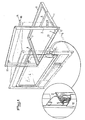
- la figure 1 est une vue en perspective éclatée d'un foyer à insérer conforme à l'invention;
- la figure 2 est une vue partielle en coupe montrant la liaison étanche entre foyer et cadre au niveau d'un montant;
- la figure 3 représente une variante de réalisation de la liaison suivant la figure 2, et
- la figure 4 est une vue partielle en coupe d'une partie de fond du foyer.
- Figure 1 is an exploded perspective view of a fireplace to be inserted according to the invention;
- Figure 2 is a partial sectional view showing the sealed connection between hearth and frame at an upright;
- FIG. 3 represents an alternative embodiment of the connection according to FIG. 2, and
- Figure 4 is a partial sectional view of a bottom portion of the hearth.
Conformément à l'invention, et comme le montre plus particulièrement, à titre d'exemple, la figure 1 des dessins annexés, le foyer 4 à insérer dans une cheminée à feu ouvert existante muni d'un dispositif de mise en place et d'étanchéité, qui le rend parfaitement amovible, constitué par des glissières horizontales 1, qui sont fixées sur la sole de la cheminée existante au moyen de vis traversant des perçages 7 prévus à cet effet, par un cadre vertical 2 relié aux glissières 1 perpendiculairement a leur plan, et par un aménagement avant 3 du foyer amovible 4, qui coopère avec le cadre vertical 2, et qui est destiné à assurer l'étanchéité par écrasement d'un joint 5. La partie inférieure du foyer amovible 4 est pourvue, en outre, d'un dispositif 6 favorisant son glissement sur les glissières 1.In accordance with the invention, and as shown more particularly, by way of example, FIG. 1 of the accompanying drawings, the
Le cadre vertical 2 est avantageusement fixé aux glissières 1 de manière démontable au moyen d'éléments 8, en fer plat, ou autre, s'étendant obliquement d'une glissière 1 au montant correspondant du cadre 2, et fixés, de préférence, au moyen de vis, une liaison par vis pouvant éqalement être prévue au niveau de la jonction de la base de chaque montant avec l'extrémité correspondante des glissières 1.The
Ces dernières sont reliées, à leur extrémité opposée au cadre vertical 2, à une traverse 9.The latter are connected, at their end opposite to the
L'aménagement avant 3 du foyer amovible 4 est constitué par un cadre rapporté 10 s'appliquant sur les montants et sur la traverse supérieure du foyer amovible 4 et portant le joint 5, qui est écrasé sur le cadre vertical 2, lors de l'insertion complète du foyer amovible 4 (figure 2).The
Conformément à une variante de réalisation de l'invention, et comme le montre la figure 3 des dessins annexés, l'aménagement avant 3 peut également être constitué par des parties repliées 11 des bords latéraux et de la traverse supérieure du foyer amovible 4, le joint 5 étant logé dans lesdites parties repliées 11.According to an alternative embodiment of the invention, and as shown in Figure 3 of the accompanying drawings, the
Le dispositif 6, équipant la partie inférieure du foyer amovible 4 (figure 4), est avantageusement constitué par des rebords 12 des parois verticales latérales du foyer 4, qui sont rabattus sur le fond de ce dernier et forment chacun une surface parfaitement plane d'application sur les glissières 1.The
Pour favoriser ce glissement, les rebords 12 sont, de préférence, munis d'un revêtement anti-adhérent, tel que du polytétrafluoréthylène, ou analogue.To promote this sliding, the
Il est également possible de réaliser le dispositif 6 par prévision de chemins de billes ou de galets (non représentés), le long des parties latérales de fond du foyer amovible 4 opposées aux glissières 1.It is also possible to produce the
Le cadre vertical 2, dont les montants sont reliés à leur base par une traverse en fer plat 13, présente avantageusement des dimensions identiques à celles du foyer amovible 4 en hauteur et en largeur avec un léger jeu de fonctionnement, et l'élément horizontal, formé par les glissières 1 et par leur traverse de liaison 9, présente des dimensions équivalentes à celles de la base du foyer amovible 4 à insérer, également avec un léger jeu de fonctionmement, et les glissières 1 sont, de préférence, en forme de cornière, et font office de rails de guidage.The
Pour assurer un maintien parfait du cadre 2 et des glissières 1 sur la sole de cheminée existante, en particulier après positionnement, les glissières 1 ainsi que la traverse inférieure 13 du cadre 2 sont avantageusement munies d'un ou de plusieurs perçages 7 pour des vis de scellement (non représentées).To ensure perfect maintenance of the
En outre, pour garantir le scellement du cadre dans la maçonnerie de fermeture de l'ouverture de foyer existante, les montants du cadre vertical 2 sont avantageusement pourvus, soit chacun d'une ou de plusieurs pattes de scellement 14, soit d'une ou de plusieurs pattes repliables 15 munies chacune d'un trou 16 de fixation par vis pour la fixation du cadre 2 sur l'intérieur des parois verticales de la cheminée existante.In addition, to guarantee the sealing of the frame in the masonry closing the existing fireplace opening, the uprights of the
Sur sa face avant, le cadre vertical 2 est muni, éventuellement, à intervalles réguliers, de trous taraudés 17 permettamt l'immobilisation et la fixation au moyem de vis du foyer amovible 4 à insérer, après sa mise en place, et évitant ainsi un déplacement accidentel dudit foyer.On its front face, the
L'étanchéité entre le foyer amovible 4 à insérer et le cadre vertical 2 est assurée par un joint unique 5 rapporté sur le cadre vertical 2, ou encore équipant ledit foyer 4, tandis que l'étanchéité entre le cadre 2 et le foyer ouvert de la cheminée existante est assurée par la maçonnerie s'appuyant contre le cadre 2 (figure 2), cette maçonnerie pouvant recevoir, le cas échéant, un habillage supplémentaire.The seal between the
Il est également possible de réaliser le jointoiement entre le cadre vertical 2 et le foyer ouvert de la cheminée existante au moyen de plaques thermiquement résistantes 18 (figure 3) s'appuyant, d'une part, contre les profilés formant le cadre 2, et d'autre part, contre un profilé 19 solidaire de la paroi verticale correspondante 20 de la cheminée existante, ces plaques 18 pouvant être en amiante-ciment, en fibro-ciment, en tôle, ou analogue.It is also possible to make the jointing between the
Conformément à une variante de réalisation de l'invention, non représentée aux dessins annexés, les glissières 1 peuvent être sous forme de rails de guidage en U coopérant avec des petits rouleaux effleurant légèrement sous la base du foyer amovible 4 à insérer. Un tel mode de réalisation permet de faciliter la manoeuvre du foyer amovible 4 lors de sa mise en place, ainsi que lors de son retrait, par exemple en vue d'un ramonage et d'un nettoyage, ou d'une autre visite d'entretien.According to an alternative embodiment of the invention, not shown in the accompanying drawings, the
Il est également possible, suivant une autre variante de réalisation de l'invention, non représentée au dessin annexé, de munir le cadre 2 derrière chaque montant d'un double rail latéral, dont l'une des parties, est solidarisée avec le côté correspondant du foyer. Il est ainsi possible de dégager le foyer hors de son logement à la manière d'un tiroir, tout en assurant son maintien par exemple dans le cas d'un foyer ouvert surélevé par rapport au sol environnant.It is also possible, according to another alternative embodiment of the invention, not shown in the accompanying drawing, to provide the
Grêce à l'invention, il est possible de réaliser un foyer amovible à insérer dans une cheminée à feu ouvert existante pouvant, d'une part, être sorti facilement pour des visites périodiques de ramonage et de nettoyage et, d'autre part, être maintenu avec une étanchéité parfaite en position de service. En outre, aucun accessoire supplémentaire de finition, pour l'étanchéité ou le montage, n'est nécessaire.Thanks to the invention, it is possible to produce a removable hearth to be inserted into an existing open fireplace which can, on the one hand, be easily removed for periodic sweeping and cleaning visits and, on the other hand, be maintained with a perfect seal in the service position. In addition, no additional finishing accessories, for sealing or mounting, are required.
En outre, le foyer amovible conforme à l'invention se présente sous forme d'un "insert sortant" pouvant être manoeuvré à la manière d'un tiroir, et est ainsi d'un accès facile, en particulier pour un remplacement de pièces défectueuses ou pour d'autres opérations d'entretien.In addition, the removable hearth according to the invention is in the form of an "outgoing insert" which can be operated in the manner of a drawer, and is thus of easy access, in particular for the replacement of defective parts. or for other operations maintenance.
Du fait de cette facilité de démontage du foyer amovible 4, une utilisation du foyer existant peut facilement être envisagée avec maintien de l'habillage, par simple démontage des glissières 1 et des éléments obliques 8. Une telle utilisation de la cheminée existante peut notamment se concevoir pendant les périodes d'intersaison, où un chauffage à haut rendement n'est pas indispensable.Because of this ease of dismantling the
Enfin, du fait de la prévision d'un joint 5 écrasé entre le cadre vertical 2 et un agencement avant 3 du foyer amovible 4, le montage de ce dernier offre une sécurité parfaite du point de vue de l'étanchéité contre les fuites éventuelles de gaz.Finally, due to the provision of a
Claims (16)
Priority Applications (1)
| Application Number | Priority Date | Filing Date | Title |
|---|---|---|---|
| AT84440045T ATE29289T1 (en) | 1983-11-07 | 1984-11-06 | STOVE WITH DEVICE FOR INSTALLATION AND SEALING FOR DISASSEMBLING INTO AN EXISTING CHIMNEY. |
Applications Claiming Priority (2)
| Application Number | Priority Date | Filing Date | Title |
|---|---|---|---|
| FR8317984 | 1983-11-07 | ||
| FR8317984A FR2554554B1 (en) | 1983-11-07 | 1983-11-07 | FIREPLACE TO BE INSERTED INTO AN EXISTING OPEN FIREPLACE PROVIDED WITH A PLACEMENT AND SEALING DEVICE MAKING IT PERFECTLY REMOVABLE |
Publications (3)
| Publication Number | Publication Date |
|---|---|
| EP0142454A2 EP0142454A2 (en) | 1985-05-22 |
| EP0142454A3 EP0142454A3 (en) | 1985-06-19 |
| EP0142454B1 true EP0142454B1 (en) | 1987-09-02 |
Family
ID=9294029
Family Applications (1)
| Application Number | Title | Priority Date | Filing Date |
|---|---|---|---|
| EP84440045A Expired EP0142454B1 (en) | 1983-11-07 | 1984-11-06 | A stove to fit into an existing fireplace in a removable way, provided with a built-in and sealing device |
Country Status (4)
| Country | Link |
|---|---|
| EP (1) | EP0142454B1 (en) |
| AT (1) | ATE29289T1 (en) |
| DE (1) | DE3465774D1 (en) |
| FR (1) | FR2554554B1 (en) |
Families Citing this family (1)
| Publication number | Priority date | Publication date | Assignee | Title |
|---|---|---|---|---|
| FR2614399B1 (en) * | 1987-04-24 | 1990-03-02 | Supra Sa | FIREPLACE TO INSERT INTO AN EXISTING OPEN FIRE CHIMNEY PROVIDED WITH A RETRACTABLE WATERPROOF CONNECTION DEVICE |
Family Cites Families (5)
| Publication number | Priority date | Publication date | Assignee | Title |
|---|---|---|---|---|
| DE70340C (en) * | F. HOUBEN in Aachen, Edelstrafse 5 | Gas stove with pull-out heater | ||
| US4036205A (en) * | 1975-05-02 | 1977-07-19 | Hayes-Te Equipment Corporation | Fireplace stove |
| US3987778A (en) * | 1976-01-08 | 1976-10-26 | Brik Michael D | Auxiliary fireplace structure |
| US4191162A (en) * | 1977-11-23 | 1980-03-04 | Simms Donald S | Energy saving air-flow heater |
| GB2096309A (en) * | 1980-09-04 | 1982-10-13 | Holroyd Peter | Mounting gas fires in place |
-
1983
- 1983-11-07 FR FR8317984A patent/FR2554554B1/en not_active Expired
-
1984
- 1984-11-06 DE DE8484440045T patent/DE3465774D1/en not_active Expired
- 1984-11-06 EP EP84440045A patent/EP0142454B1/en not_active Expired
- 1984-11-06 AT AT84440045T patent/ATE29289T1/en active
Also Published As
| Publication number | Publication date |
|---|---|
| FR2554554A1 (en) | 1985-05-10 |
| EP0142454A3 (en) | 1985-06-19 |
| DE3465774D1 (en) | 1987-10-08 |
| ATE29289T1 (en) | 1987-09-15 |
| EP0142454A2 (en) | 1985-05-22 |
| FR2554554B1 (en) | 1987-05-15 |
Similar Documents
| Publication | Publication Date | Title |
|---|---|---|
| FR2597196A1 (en) | SOLID FUEL STOVE, IN PARTICULAR A WOOD STOVE EQUIPPED WITH A DEVICE FOR CLEANING TRANSPARENT WALLS | |
| CA1167724A (en) | Heat collector for installation in a house flue, and related method for heating a fluid such as water | |
| EP0142454B1 (en) | A stove to fit into an existing fireplace in a removable way, provided with a built-in and sealing device | |
| EP0364358B1 (en) | Seat support for public transport vehicles and seat equipped with this support | |
| CH635186A5 (en) | HOT AIR GENERATOR FOR MOUNTING IN AN OPEN FIRE CHIMNEY. | |
| EP2149751B1 (en) | Covering device for a conduit connecting a heating device and a flue, and method for installing the same | |
| FR3103505A1 (en) | Roof reservation system, for the subsequent installation of a duct | |
| FR2597195A1 (en) | ASHTRAY ASSEMBLY FOR WOOD STOVE, INCORPORATED INTO HIS DOOR, AND PROVIDED WITH A SAFETY COVER | |
| EP0293313A1 (en) | Stove for insertion into an existing fire place provided with an air-tight and retractable joining device | |
| FR2619893A1 (en) | Heating appliance, producing hot air, which can be used in any environment, even an inflammable one | |
| EP1266593B1 (en) | Anti-tilt device for household appliance insertable in a recess | |
| FR2654495A1 (en) | Fireplace for the closed hearth | |
| FR2649473A1 (en) | Device for connecting up the flue and/or air inlet and/or hot air outlet pipes of built-in gas-fired heating appliances | |
| FR2581736A1 (en) | Closed hearth for apartment fireplace | |
| FR3048488B1 (en) | HEATING INSTALLATION FOR A BUILDING | |
| FR2667097A1 (en) | Fireplace with suspended hood independent of the hearth | |
| FR2825599A1 (en) | Ready-to build kit for fitting microwave oven into recess, comprises separating plate adjustable in height and located between oven and recess bases, and feet which support oven through plate holes | |
| FR2601061A1 (en) | Device for preparing a masonry framing particularly for the sealed insertion of an added element | |
| FR2597964A1 (en) | Metal hearth for a fireplace | |
| FR2556079A1 (en) | Stove producing hot air which can be formed by means of cast iron modules moulded without a core | |
| FR2540606A1 (en) | Solid fuel stove | |
| FR2613043A1 (en) | Fire shield device with built-in directional draught stabiliser intended to equip open hearths | |
| EP0916772A1 (en) | Technical support frame | |
| FR2683892A1 (en) | Base for closed fireplace hearth, provided with an ash box access offset towards the front | |
| FR2594214A1 (en) | HEAT RECOVERY APPARATUS FOR OPEN FIREPLACE |
Legal Events
| Date | Code | Title | Description |
|---|---|---|---|
| PUAI | Public reference made under article 153(3) epc to a published international application that has entered the european phase |
Free format text: ORIGINAL CODE: 0009012 |
|
| PUAL | Search report despatched |
Free format text: ORIGINAL CODE: 0009013 |
|
| AK | Designated contracting states |
Designated state(s): AT BE CH DE GB IT LI LU NL SE |
|
| AK | Designated contracting states |
Designated state(s): AT BE CH DE GB IT LI LU NL SE |
|
| RTI1 | Title (correction) | ||
| 17P | Request for examination filed |
Effective date: 19851106 |
|
| 17Q | First examination report despatched |
Effective date: 19860610 |
|
| GRAA | (expected) grant |
Free format text: ORIGINAL CODE: 0009210 |
|
| AK | Designated contracting states |
Kind code of ref document: B1 Designated state(s): AT BE CH DE GB IT LI LU NL SE |
|
| PG25 | Lapsed in a contracting state [announced via postgrant information from national office to epo] |
Ref country code: NL Effective date: 19870902 |
|
| REF | Corresponds to: |
Ref document number: 29289 Country of ref document: AT Date of ref document: 19870915 Kind code of ref document: T |
|
| REF | Corresponds to: |
Ref document number: 3465774 Country of ref document: DE Date of ref document: 19871008 |
|
| ITF | It: translation for a ep patent filed |
Owner name: STUDIO INGG. FISCHETTI & WEBER |
|
| PG25 | Lapsed in a contracting state [announced via postgrant information from national office to epo] |
Ref country code: LU Free format text: LAPSE BECAUSE OF NON-PAYMENT OF DUE FEES Effective date: 19871130 |
|
| NLV1 | Nl: lapsed or annulled due to failure to fulfill the requirements of art. 29p and 29m of the patents act | ||
| GBV | Gb: ep patent (uk) treated as always having been void in accordance with gb section 77(7)/1977 [no translation filed] | ||
| PLBI | Opposition filed |
Free format text: ORIGINAL CODE: 0009260 |
|
| 26 | Opposition filed |
Opponent name: SOCIETE AUER Effective date: 19880415 |
|
| PLAB | Opposition data, opponent's data or that of the opponent's representative modified |
Free format text: ORIGINAL CODE: 0009299OPPO |
|
| R26 | Opposition filed (corrected) |
Opponent name: SOCIETE AUER Effective date: 19880415 |
|
| PG25 | Lapsed in a contracting state [announced via postgrant information from national office to epo] |
Ref country code: GB Free format text: LAPSE BECAUSE OF NON-PAYMENT OF DUE FEES Effective date: 19881123 |
|
| PGFP | Annual fee paid to national office [announced via postgrant information from national office to epo] |
Ref country code: SE Payment date: 19891110 Year of fee payment: 6 |
|
| PGFP | Annual fee paid to national office [announced via postgrant information from national office to epo] |
Ref country code: AT Payment date: 19891114 Year of fee payment: 6 |
|
| PGFP | Annual fee paid to national office [announced via postgrant information from national office to epo] |
Ref country code: CH Payment date: 19900227 Year of fee payment: 6 |
|
| PG25 | Lapsed in a contracting state [announced via postgrant information from national office to epo] |
Ref country code: AT Effective date: 19901106 |
|
| PG25 | Lapsed in a contracting state [announced via postgrant information from national office to epo] |
Ref country code: SE Effective date: 19901107 |
|
| PGFP | Annual fee paid to national office [announced via postgrant information from national office to epo] |
Ref country code: DE Payment date: 19901116 Year of fee payment: 7 |
|
| PGFP | Annual fee paid to national office [announced via postgrant information from national office to epo] |
Ref country code: BE Payment date: 19901129 Year of fee payment: 7 |
|
| PG25 | Lapsed in a contracting state [announced via postgrant information from national office to epo] |
Ref country code: LI Effective date: 19901130 Ref country code: CH Effective date: 19901130 |
|
| REG | Reference to a national code |
Ref country code: CH Ref legal event code: PL |
|
| PLBN | Opposition rejected |
Free format text: ORIGINAL CODE: 0009273 |
|
| STAA | Information on the status of an ep patent application or granted ep patent |
Free format text: STATUS: OPPOSITION REJECTED |
|
| 27O | Opposition rejected |
Effective date: 19910419 |
|
| ITTA | It: last paid annual fee | ||
| PG25 | Lapsed in a contracting state [announced via postgrant information from national office to epo] |
Ref country code: BE Effective date: 19911130 |
|
| BERE | Be: lapsed |
Owner name: SUPRA FABRIQUE D'APPAREILS DE CHAUFFAGE ET DE CUI Effective date: 19911130 |
|
| PG25 | Lapsed in a contracting state [announced via postgrant information from national office to epo] |
Ref country code: DE Effective date: 19920801 |
|
| EUG | Se: european patent has lapsed |
Ref document number: 84440045.7 Effective date: 19910705 |
|
| APAH | Appeal reference modified |
Free format text: ORIGINAL CODE: EPIDOSCREFNO |