EP0142140A2 - Abrasive belt with a junction reinforced with a synthetic resin strip - Google Patents
Abrasive belt with a junction reinforced with a synthetic resin strip Download PDFInfo
- Publication number
- EP0142140A2 EP0142140A2 EP84113528A EP84113528A EP0142140A2 EP 0142140 A2 EP0142140 A2 EP 0142140A2 EP 84113528 A EP84113528 A EP 84113528A EP 84113528 A EP84113528 A EP 84113528A EP 0142140 A2 EP0142140 A2 EP 0142140A2
- Authority
- EP
- European Patent Office
- Prior art keywords
- synthetic resin
- belt
- fibers
- tape
- sanding
- Prior art date
- Legal status (The legal status is an assumption and is not a legal conclusion. Google has not performed a legal analysis and makes no representation as to the accuracy of the status listed.)
- Withdrawn
Links
Images

Classifications
-
- B—PERFORMING OPERATIONS; TRANSPORTING
- B24—GRINDING; POLISHING
- B24D—TOOLS FOR GRINDING, BUFFING OR SHARPENING
- B24D11/00—Constructional features of flexible abrasive materials; Special features in the manufacture of such materials
- B24D11/06—Connecting the ends of materials, e.g. for making abrasive belts
-
- F—MECHANICAL ENGINEERING; LIGHTING; HEATING; WEAPONS; BLASTING
- F16—ENGINEERING ELEMENTS AND UNITS; GENERAL MEASURES FOR PRODUCING AND MAINTAINING EFFECTIVE FUNCTIONING OF MACHINES OR INSTALLATIONS; THERMAL INSULATION IN GENERAL
- F16G—BELTS, CABLES, OR ROPES, PREDOMINANTLY USED FOR DRIVING PURPOSES; CHAINS; FITTINGS PREDOMINANTLY USED THEREFOR
- F16G3/00—Belt fastenings, e.g. for conveyor belts
- F16G3/10—Joining belts by sewing, sticking, vulcanising, or the like; Constructional adaptations of the belt ends for this purpose
Definitions
- the invention relates to an abrasive belt with a connection point bridged by a synthetic resin belt containing reinforcing fibers.
- Endless sanding belts are made by joining the ends of a piece of sanding belt.
- the connection must have sufficient strength and dimensional stability without significantly changing the properties of the tape at the connection point.
- the connection point must not be, or not significantly thicker than, the other sanding belt.
- the connection of the ends of the sanding belt is known by a synthetic resin belt bridging the connection point, which is glued to the adjacent edges of the back of the sanding belt (DE-OS 24 50 775). It is known to provide this tape with fabric to give it greater strength and possibly also to allow a reduction in its thickness compared to unreinforced synthetic resin tape (DE-OS 20 22 316; DE-OS 24 52 589).
- a direction deviating from the cross-band direction is chosen for the direction of the connection in the form of a so-called diagonal butt joint. This is to prevent the connection point from running simultaneously on a deflection roller over the entire bandwidth, which can not only lead to considerable noise pollution, but also reduces the processing quality and the durability of the grinding belt.
- the synthetic resin band bridging the connection point also runs correspondingly obliquely. If the thread direction of the reinforcing fabric contained therein corresponds to the longitudinal direction of the synthetic resin belt, which is the simplest for the production, then the fabric threads run obliquely to the longitudinal direction of the grinding belt and thus also obliquely to the main direction of stress of the connection, which can lead to undesirable stretching and loss of strength.
- the invention is therefore based on the object of an abrasive belt of the type mentioned or a synthetic resin to connect the ends of the ends or to create a method for producing such an abrasive belt, which, with a small thickness of the synthetic resin band, combine high strength with little thickening of the connection point regardless of the helix angle of the abrasive belt connection.
- the solution according to the invention consists in that the fibers reinforcing the synthetic resin tape are oriented to a substantial extent in a confused manner.
- the solution seems to be in contrast to the experience that when reinforcing the fabric with threads running at an angle to the longitudinal direction of the tape, sufficient strength and elongation values are not achieved, because even with the tangled arrangement of the reinforcing fibers, it can be expected that the majority of the Fibers run at an angle to the longitudinal direction of the tape.
- the invention has recognized that, in known fabric-reinforced synthetic resin tapes, the strength of the fabric, measured in the longitudinal direction of the thread, is generally much higher than is required for the connection purposes and as to forces on the reinforcing threads by the synthetic resin material of the tape containing them or by the adhesive connecting the synthetic resin belt to the back of the sanding belt can be transferred.
- the invention also includes the knowledge that the tangled arrangement of the reinforcing fibers facilitates the transmission of force to that (in itself small) portion of the fibers that run in the longitudinal direction of the tape.
- each individual fiber is anchored more securely within the matrix surrounding it due to its curvatures and the large number of evenly distributed fiber crossing points than the individual fibers of a straight thread, of which at most the outer fibers (and also often only partially) are a direct bond with the surrounding synthetic resin.
- each individual reinforcing fiber running in the longitudinal direction of the sanding belt is significantly more involved in the power transmission in a tangled arrangement than in a thread fabric arrangement. This is also an explanation for the fact that in a tangled fiber arrangement the number of fibers running in the longitudinal direction of the sanding belt does not have to be nearly as large as in the case of a fabric reinforcement in order to achieve sufficient connection strength.
- the suitability of a fiber-reinforced plastic belt for increased force absorption in any direction in sanding belt connections can also be particularly advantageous because sanding belts in general and, consequently, their connection points when grinding curved objects are frequently exposed to forces that do not only run in the longitudinal direction.
- the suitability of tangled fiber-reinforced synthetic resin tapes is particularly valuable for such abrasive tape connections, the joint of which does not run straight, but wavy serrated or interlocking, because the forces to be transmitted through the bridging synthetic resin tape can be directed differently depending on the local direction of the joint.
- synthetic resin is understood to mean any synthetic, polymeric material that is suitable in tape form for force-transmitting joint bridging and for embedding fiber material.
- polyesters, polyamides and polyimides are primarily suitable.
- Asl fiber material is primarily suitable for glass, carbon and high-strength synthetic resins such as aramid, but also mineral and metallic fibers.
- Their length is preferably in the range of 0.3-50 mm.
- the titer is expediently chosen between 2 den and 80 den.
- the choice of fiber lengths and thicknesses is of course also dependent to a certain extent on the thickness of the tape film used, which is advantageously between 0.025 mm and 0.35 mm.
- the reinforcing fibers are distributed substantially uniformly in the synthetic resin band.
- a tape with reinforcing fibers distributed substantially uniformly over the cross section can be obtained, for example, by extrusion or casting of melted synthetic resin containing the fibers. If there is a certain transverse orientation of the fibers as a result of the flow processes in the nozzle, this does not necessarily have to be disadvantageous because, on the one hand, a sufficient proportion of fibers with different orientations remains and, on the other hand, the transversely oriented fibers are predominant with regard to the predominantly transverse fibers ongoing stress on the synthetic resin tape may well be appropriate. Furthermore, such predominant transverse orientation may achbearbeitungshabilit by N, which tend to increase the longitudinal orientation, such as calendering, can be compensated.
- Such an embodiment can also be expedient, in which the fibers in the synthetic resin belt are predominantly arranged on its cross-sectional side facing the grinding belt, so that the connecting forces have to be transmitted in the form of shear stresses over a smaller thickness range of the synthetic resin belt. On the one hand, this gives greater security; secondly, less elongation.
- the reinforcing fibers can be at least partially exposed on the surface of the synthetic resin belt facing the grinding belt.
- the strength of the connection of the synthetic resin belt with a binder layer located between the latter and the back of the grinding belt can be improved.
- a layered structure of the synthetic resin tape is advisable, but it can also have advantages in another context.
- the synthetic resin belt can be glued to the adjacent edges of the sanding belt ends to be connected.
- the adhesives which have been tried and tested in the prior art can be used for this.
- the prefabricated synthetic resin belt can also be pressed onto the abrasive belt, optionally provided with an adhesion promoter or adhesive, in the uncured state and left to harden.
- synthetic resin that is not or only partially polymerized can be used. It can also be applied as a melt when using a thermoplastic material. If the synthetic resin belt is built up in layers, there is also the possibility that the uncured state when applying the belt only relates to the layer facing the grinding belt. This process has a particular advantage not only in that an intimate connection between the synthetic resin belt and the back of the grinding belt can be achieved, possibly without thicker layers of binder, but that in many cases a cross-sectional shaping of the belt can also take place.
- the overlapping band can be pressed into the flat cavity formed thereby. so that it has a complementary double wedge-shaped cross section.
- a preformed tape is placed on the connection point in the plastic state and then pressed. Instead, it can be applied directly from a nozzle in the plastic state, distributed and - with or without applying pressure - allowed to harden without preforming.
- one possibility for applying the synthetic resin tape on the back of the sanding belt is that the synthetic resin tape is built up in layers on the sanding belt by at least partially pressing a tangled nonwoven into an initially applied plastic synthetic resin layer, after which the synthetic resin layer is allowed to harden.
- One or more further layers, the last as a top layer, can also be applied.
- the fibers can be preformed in a fleece shape or can be sprinkled in loosely.
- the grinding belt 1, which runs over deflection rollers 2, is endless from the originally stretched state by connecting its ends in the area of the connection point 3.
- the connection point 3 runs obliquely at an angle 4 with respect to the transverse direction of the grinding belt.
- the joint 7 of the connection point can run in a straight line or not in a straight line; 3 shows a wave cut connection.
- the sanding belt consists of the tensile, flexible base 5 and the abrasive grain covering 6. At 7, the joint between the belt ends to be connected can be seen.
- connection is mediated by the synthetic resin tape 8, which is connected to the adjacent edges 9 of the back of the sanding belt, for example for gluing.
- the synthetic resin tape 8 includes reinforcing fibers may be chopped short, as shown at 10 in Fig. 5 schematically (although much too coarse) F as shown, or may also be very long, ig. 6 illustrated at 11.
- the reinforcing fibers can also be mixed from short to long fibers 10, 11, as shown in FIG. 7. 8, the fibers 10, 11 can be distributed uniformly over the entire cross section of the exaggeratedly thick synthetic resin tape 8. According to FIG. 9, however, they can also have a higher concentration, in particular in the form of a layer, in the vicinity of that surface 12 of the synthetic resin belt which is intended to be glued to the back of the grinding belt.
- the reinforcing fibers are preferably predominantly oriented in the plane of the synthetic resin tape, which can be accomplished, for example, by stretching the tape in the longitudinal and / or transverse direction after casting.
- the fibers 10, 11 according to FIG. 10 protrude beyond the surface 12 or are at least partially exposed in it, they can form an intimate connection with the binder layer 13, which in the example shown is provided between the back of the sanding belt base 5 and the synthetic resin belt 8 is.
- the synthetic resin band 14 is molded into the depression which was formed by wedge-shaped beveling of the edges 15 of the abrasive belt ends to be connected.
Abstract
Description
Die Erfindung bezieht sich auf ein Schleifband mit einer durch ein verstärkende Fasern enthaltendes Kunstharzband überbrückten Verbindungsstelle.The invention relates to an abrasive belt with a connection point bridged by a synthetic resin belt containing reinforcing fibers.
Endlose Schleifbänder werden durch Verbinden der Enden eines Schleifbandstücks hergestellt. Die Verbindung muß eine hinreichende Festigkeit und Formbeständigkeit aufweisen, ohne die Eigenschaften des Bandes an der Verbindungsstelle wesentlich zu ändern. Insbesondere darf die Verbindungsstelle nicht oder nicht wesentlich dicker als das sonstige Schleifband sein. Bekannt ist die Verbindung der Schleifbandenden durch ein die Verbindungsstelle überbrückendes Kunstharzband, das mit den benachbarten Rändern der Schleifbandrückseite verklebt ist (DE-OS 24 50 775). Es ist bekannt, dieses Band mit Gewebe auszurüsten, um ihm größere Festigkeit zu verleihen und ggf. auch eine Herabsetzung seiner Dicke gegenüber unverstärktem Kunstharzband zu ermöglichen (DE-OS 20 22 316; DE-OS 24 52 589). Im allgemeinen wählt man für die Richtung der Verbindung eine von der Bandquerrichtung abweichende Richtung in Gestalt einer sog. Schrägstoßverbindung. Dadurch soll vermieden werden, daß die Verbindungsstelle über die gesamte Bandbreite gleichzeitig auf einer Umlenkrolle aufläuft, was nicht nur zu einer beträchtlichen Geräuschbelästigung führen kann, sondern auch die Bearbeitungsqualität und die Haltbarkeit des Schleifbands verringert. Entsprechend schräg verläuft auch das die Verbindungsstelle überbrückende Kunstharzband. Wenn die Fadenrichtung des darin enthaltenen Verstärkungsgewebes mit der Längsrichtung des Kunstharzbandes übereinstimmt, was für die Herstellung am einfachsten ist, so verlaufen die Gewebefäden schräg zur Längsrichtung des Schleifbandes und damit auch schräg zur Hauptbeanspruchungsrichtung der Verbindung, was zu unerwünschten Dehnungen und Festigkeitseinbußen führen kann. Man kann das Gewebe in dem Kunstharzband auch so anordnen, daß seine Fäden in Schleifbandlängsrichtung verlaufen; dies setzt jedoch voraus, daß das Kunstharzband aus einem größeren Stück gewebeverstärkter Kunststoffolie schräg geschnitten wird unter einem Winkel, der der Schrägungsrichtung der Schleifbandverbindung entspricht. Dies ist materialaufwendig und umständlich und demzufolge kostspielig. Das gilt auch für eine Schleifbandverbindung, die in einer Richtung orientierte Verstärkungsfasern enthält (US-PS 4 215 516). - Wenn man zur Vermeidung der mit der Verwendung von Gewebeverstärkung verbundenen Nachteile unverstärktes Kunstharzband verwendet, so muß man zur Erzielung der erforderlichen Festigkeit dies in größerer Dicke verwenden, was in vielen Fällen nicht statthaft ist.Endless sanding belts are made by joining the ends of a piece of sanding belt. The connection must have sufficient strength and dimensional stability without significantly changing the properties of the tape at the connection point. In particular, the connection point must not be, or not significantly thicker than, the other sanding belt. The connection of the ends of the sanding belt is known by a synthetic resin belt bridging the connection point, which is glued to the adjacent edges of the back of the sanding belt (DE-OS 24 50 775). It is known to provide this tape with fabric to give it greater strength and possibly also to allow a reduction in its thickness compared to unreinforced synthetic resin tape (DE-OS 20 22 316; DE-OS 24 52 589). In general, a direction deviating from the cross-band direction is chosen for the direction of the connection in the form of a so-called diagonal butt joint. This is to prevent the connection point from running simultaneously on a deflection roller over the entire bandwidth, which can not only lead to considerable noise pollution, but also reduces the processing quality and the durability of the grinding belt. The synthetic resin band bridging the connection point also runs correspondingly obliquely. If the thread direction of the reinforcing fabric contained therein corresponds to the longitudinal direction of the synthetic resin belt, which is the simplest for the production, then the fabric threads run obliquely to the longitudinal direction of the grinding belt and thus also obliquely to the main direction of stress of the connection, which can lead to undesirable stretching and loss of strength. You can also arrange the fabric in the synthetic resin tape so that its threads run in the longitudinal direction of the sanding belt; however, this presupposes that the synthetic resin band is cut obliquely from a larger piece of fabric-reinforced plastic film at an angle which corresponds to the direction of bevel of the abrasive belt connection. This is material-intensive and cumbersome and therefore expensive. This also applies to an abrasive belt connection that contains unidirectional reinforcing fibers (US Pat. No. 4,215,516). If, in order to avoid the disadvantages associated with the use of fabric reinforcement, unreinforced synthetic resin tape is used, then in order to achieve the required strength, this must be used in greater thickness, which in many cases is not permissible.
Der Erfindung liegt daher die Aufgabe zugrunde, ein Schleifband der eingangs genannten Art bzw. ein Kunstharzband zum Verbinden von dessen Enden bzw. ein Verfahren zur Herstellung eines solchen Schleifbandes zu schaffen, die bei geringer Dicke des Kunstharzbandes unabhängig vom Schrägungswinkel der Schleifbandverbindung hohe Festigkeit mit geringer Verdickung der Verbindungsstelle verbinden.The invention is therefore based on the object of an abrasive belt of the type mentioned or a synthetic resin to connect the ends of the ends or to create a method for producing such an abrasive belt, which, with a small thickness of the synthetic resin band, combine high strength with little thickening of the connection point regardless of the helix angle of the abrasive belt connection.
Die erfindungsgemäße Lösung besteht darin, daß die das Kunstharzband verstärkenden Fasern zu einem wesentlichen Anteil wirr orientiert sind.The solution according to the invention consists in that the fibers reinforcing the synthetic resin tape are oriented to a substantial extent in a confused manner.
Auf den ersten Blick scheint die Lösung in Gegensatz zu stehen zu der Erfahrung, daß bei einer Gewebeverstärkung mit winklig zur Bandlängsrichtung verlaufenden Fäden keine hinreichenden Festigkeiten und Dehnungswerte erreicht werden, denn auch bei wirrer Anordnung der Verstärkungsfasern ist damit zu rechnen, daß der größte Teil der Fasern winklig zur Bandlängsrichtung verläuft. Jedoch hat die Erfindung erkannt, daß bei bekannten gewebeverstärkten Kunstharzbändern die Festigkeit des Gewebes, in Fadenlängsrichtung gemessen, im allgemeinen wesentlich höher ist als dies für die Verbindungszwecke erforderlich ist und als an Kräften auf die verstärkenden Fäden durch das sie enthaltende Kunstharzmaterial des Bandes bzw. durch den das Kunstharzband mit der Schleifbandrückseite verbindenden Kleber übertragen werden kann. Dies führt zu dem Schluß, daß auch eine wesentlich geringere Anzahl von in Bandlängsrichtung verlaufenden Fasern zu einer hinreichenden Verstärkung führen kann. - - Ferner beinhaltet die Erfindung die Erkenntnis, daß die wirre Anordnung der Verstärkungsfasern die Kraftübertragung auf denjenigen (an sich kleinen) Anteil der Fasern erleichtert, die in Bandlängsrichtung verlaufen.At first glance, the solution seems to be in contrast to the experience that when reinforcing the fabric with threads running at an angle to the longitudinal direction of the tape, sufficient strength and elongation values are not achieved, because even with the tangled arrangement of the reinforcing fibers, it can be expected that the majority of the Fibers run at an angle to the longitudinal direction of the tape. However, the invention has recognized that, in known fabric-reinforced synthetic resin tapes, the strength of the fabric, measured in the longitudinal direction of the thread, is generally much higher than is required for the connection purposes and as to forces on the reinforcing threads by the synthetic resin material of the tape containing them or by the adhesive connecting the synthetic resin belt to the back of the sanding belt can be transferred. This leads to the conclusion that a substantially smaller number of fibers running in the longitudinal direction of the tape can lead to sufficient reinforcement. - - The invention also includes the knowledge that the tangled arrangement of the reinforcing fibers facilitates the transmission of force to that (in itself small) portion of the fibers that run in the longitudinal direction of the tape.
Bei einer Wirrfaseranordnung ist nämlich jede einzelne Faser innerhalb der sie umgebenden Matrix infolge ihrer Krümmungen und der Vielzahl gleichmäßig verteilter Faserkreuzungspunkte sicherer verankert als die einzelnen Fasern eines gerade durchlaufenden Fadens, von dem höchstens die außenliegenden Fasern (und auch diese oft nur teilweise) einen direkten Verbund mit dem umgebenden Kunstharz aufzuweisen haben. Demzufolge wird jede einzelne in Schleifbandlängsrichtung verlaufende Verstärkungsfaser bei wirrer Anordnung wesentlich stärker an der Kraftübertragung beteiligt als in einer Fadengewebeanordnung. Auch dies ist eine Erklärung dafür, daß bei einer Wirrfaseranordnung die Zahl der in Schleifbandlängsrichtung verlaufenden Fasern zur Erreichung hinreichender Verbindungsfestigkeit bei weitem nicht so groß zu sein braucht wie im Falle einer Gewebeverstärkung. - Schließlich kann die Eignung eines wirrfaserverstärkten Kunststoffbandes zur erhöhten Kraftaufnahme in jeder beliebigen Richtung bei Schleifbandverbindungen auch deshalb besonders vorteilhaft sein, weil Schleifbänder allgemein und demzufolge auch deren Verbindungsstellen beim Schleifen gewölbter Gegenstände häufig Kräften ausgesetzt werden, die nicht nur in Längsrichtung verlaufen. - Besonders wertvoll ist die Eignung von wirrfaserverstärkten Kunstharzbändern bei solchen Schleifbandverbindungen, deren Fuge nicht gerade, sondern wellenförmig gezackt oder gefingert ineinandergreifend verläuft, weil bei diesen die durch das überbrückende Kunstharzband zu übertragenden Kräfte je nach örtlicher Richtung der Fuge unterschiedlich gerichtet sein können.In a tangled fiber arrangement, each individual fiber is anchored more securely within the matrix surrounding it due to its curvatures and the large number of evenly distributed fiber crossing points than the individual fibers of a straight thread, of which at most the outer fibers (and also often only partially) are a direct bond with the surrounding synthetic resin. As a result, each individual reinforcing fiber running in the longitudinal direction of the sanding belt is significantly more involved in the power transmission in a tangled arrangement than in a thread fabric arrangement. This is also an explanation for the fact that in a tangled fiber arrangement the number of fibers running in the longitudinal direction of the sanding belt does not have to be nearly as large as in the case of a fabric reinforcement in order to achieve sufficient connection strength. - Finally, the suitability of a fiber-reinforced plastic belt for increased force absorption in any direction in sanding belt connections can also be particularly advantageous because sanding belts in general and, consequently, their connection points when grinding curved objects are frequently exposed to forces that do not only run in the longitudinal direction. - The suitability of tangled fiber-reinforced synthetic resin tapes is particularly valuable for such abrasive tape connections, the joint of which does not run straight, but wavy serrated or interlocking, because the forces to be transmitted through the bridging synthetic resin tape can be directed differently depending on the local direction of the joint.
Es ist zwar bekannt (GB-PS 1 457 986),eine Verstärkungsschicht auf die Rückseite eines Schleifbands aufzubringen, die als druckempfindliches Band ausgebildet ist und wirr orientierte Fasern enthält; jedoch dient diese Verstärkungsschicht nicht zur Verbindung der Schleifbandenden an der Stoßstelle. Sie soll in erster Linie die Reibeigenschaften bezüglich der Mitnahme des Schleifbands an der angetriebenen Rolle verbessern. Darüber hinaus verbessert sie auch - wie jede zusätzliche Schicht, welcher Art sie auch sei - die Zugfestigkeit des Bandes insgesamt. Jedoch ließ sich daraus nicht entnehmen, daß ein Kunstharzband, das wirr orientierte Fasern enthält, sich allein für die hochbeanspruchte Stoßverbindung eines Schleifbandes eignen würde, nachdem zuvor alle Versuche auf die Verwendung von orientierten Fasern gerichtet gewesen waren.It is known (GB-PS 1 457 986) to apply a reinforcing layer to the back of an abrasive belt which is designed as a pressure-sensitive belt and contains tangled fibers; however, this reinforcement layer is not used to connect the ends of the sanding belt at the joint. It is primarily intended to improve the frictional properties with regard to driving the grinding belt on the driven roller. About that it also improves the tensile strength of the belt as a whole, like any additional layer, whatever its type. However, it could not be inferred from this that a synthetic resin tape containing tangled fibers would only be suitable for the highly stressed butt joint of an abrasive belt, after all attempts had previously been directed towards the use of oriented fibers.
Unter Kunstharz ist im Zusammenhang der Verbindung jeder synthetische, polymere Werkstoff zu verstehen, der sich in Bandform zur kraftübertragenden Fugenüberbrückung sowie zur Einbettung von Fasermaterial eignet. In erster Linie kommen beispielsweise Polyester, Polyamide und Polyimide in Frage. Asl Fasermaterial eignen sich vornehmlich Glas, Kohlenstoff und hochfeste Kunstharze wie Aramid, aber auch mineralische und metallische Fasern. Ihre Länge liegt vorzusweise im Bereich vom 0,3-50 mm. Der Titer wird zweckmäßigerweise zwischen 2 den und 80 den gewählt. Die Wahl der Faserlängen und -dicken ist selbstverständlich auch bis zu einem gewissen Grade von der Dicke der verwendeten Bandfolie abhängig, die zweckmäßigerweise zwischen 0,025 mm und 0,35 mm liegt.In the context of the connection, synthetic resin is understood to mean any synthetic, polymeric material that is suitable in tape form for force-transmitting joint bridging and for embedding fiber material. For example, polyesters, polyamides and polyimides are primarily suitable. Asl fiber material is primarily suitable for glass, carbon and high-strength synthetic resins such as aramid, but also mineral and metallic fibers. Their length is preferably in the range of 0.3-50 mm. The titer is expediently chosen between 2 den and 80 den. The choice of fiber lengths and thicknesses is of course also dependent to a certain extent on the thickness of the tape film used, which is advantageously between 0.025 mm and 0.35 mm.
Es ist zweckmäßig, wenn die Verstärkungsfasern in dem Kunstharzband im wesentlichen gleichmäßig verteilt sind. Ein Band mit im wesentlichen gleichmäßig über den Querschnitt verteilten Verstärkungsfasern kann beispielsweise durch Extrusion oder Gießen von die Fasern enthaltendem, schmelzflüssigem Kunstharz erhalten werden. Wenn sich infolge der Strömungsvorgänge in der Düse eine gewisse Querorientierung der Fasern einstellt, so muß dies nicht unbedingt nachteilig sein, weil zum einen ein hinreichender Anteil auch noch anders orientierter Fasern verbleibt und zum anderen ein Übergewicht der quer orientierten Fasern im Hinblick auf die überwiegend quer verlaufende Beanspruchung des Kunstharzbandes durchaus zweckmäßig sein kann. Im übrigen kann eine solche überwiegende Querorientierung durch Nachbearbeitungsverfahren, die zu einer Vermehrung der Längsorientierung neigen, wie z.B. Kalandrieren, kompensiert werden.It is expedient if the reinforcing fibers are distributed substantially uniformly in the synthetic resin band. A tape with reinforcing fibers distributed substantially uniformly over the cross section can be obtained, for example, by extrusion or casting of melted synthetic resin containing the fibers. If there is a certain transverse orientation of the fibers as a result of the flow processes in the nozzle, this does not necessarily have to be disadvantageous because, on the one hand, a sufficient proportion of fibers with different orientations remains and, on the other hand, the transversely oriented fibers are predominant with regard to the predominantly transverse fibers ongoing stress on the synthetic resin tape may well be appropriate. Furthermore, such predominant transverse orientation may achbearbeitungsverfahren by N, which tend to increase the longitudinal orientation, such as calendering, can be compensated.
Zweckmäßig kann auch eine solche Ausführungsform sein, bei welcher die Faserns in dem Kunstharzband überwiegend auf dessen dem Schleifband zugekehrten Querschnittseite angeordnet sind, damit die Verbindungskräfte über einen geringeren Dickenbereich des Kunstharzbandes in Form von Schubspannungen übertragen werden müssen. Zum einen ergibt dies größere Sicherheit; zum anderen geringere Dehnung.Such an embodiment can also be expedient, in which the fibers in the synthetic resin belt are predominantly arranged on its cross-sectional side facing the grinding belt, so that the connecting forces have to be transmitted in the form of shear stresses over a smaller thickness range of the synthetic resin belt. On the one hand, this gives greater security; secondly, less elongation.
Nach einem besonderen'Merkmal der Erfindung können die Verstärkungsfasern an der dem Schleifband zugekehrten Oberfläche des Kunstharzbandes wenigstens teilweise frei liegen. Dadurch kann nämlich die Festigkeit der Verbindung des Kunstharzbandes mit einer zwischen diesem und der Schleifbandrückseite befindlichen Bindemittelschicht verbessert werden. Besonders in diesem Zusammenhang bietet sich ein schichtförmiger Aufbau des Kunstharzbandes an, der aber auch in anderem Zusammenhang Vorteile haben kann.According to a special feature of the invention, the reinforcing fibers can be at least partially exposed on the surface of the synthetic resin belt facing the grinding belt. As a result, the strength of the connection of the synthetic resin belt with a binder layer located between the latter and the back of the grinding belt can be improved. In this context, in particular, a layered structure of the synthetic resin tape is advisable, but it can also have advantages in another context.
Wie an sich bekannt, kann das Kunstharzband mit den benachbarten Rändern der zu verbindenden Schleifbandenden verklebt sein. Dafür können die im Stand der Technik bewährten Kleber verwendet werden.As is known per se, the synthetic resin belt can be glued to the adjacent edges of the sanding belt ends to be connected. The adhesives which have been tried and tested in the prior art can be used for this.
Alternativ kann auch das vorgefertigte Kunstharzband im nicht ausgehärteten Zustand auf das ggf. mit einem Haftvermittler oder Haftmittel versehene Schleifband aufgepreßt und aushärten gelassen werden. Beispielsweise kann nicht oder nur teilweise polymerisiertes Kunstharz verwendet werden. Es kann auch bei Verwendung eines thermoplastischen Werkstoffs schmelzflüssig aufgetragen werden. Bei schichtweisem Aufbau des Kunstharzbandes besteht auch die Möglichkeit, daß sich der nicht ausgehärtete Zustand beim Auftrag des Bandes nur auf dessen dem Schleifband zugewendete Schicht bezieht. Ein besonderer Vorteil dieses Verfahrens besteht nicht nur darin, daß sich eine innige Verbindung zwischen Kunstharzband und Schleifbandrückseite , ggf. ohne dickere Bindemittelschichten,erzielen läßt, sondern daß in vielen Fällen auch noch eine Querschnittsformung des Bandes stattfinden kann. Wenn beispielsweise die an die Fuge angrenzenden Ränder keilförmig angeschliffen sind, kann das überlappende Band in die dadurch gebildete flache Höhlung eingepreßt werden. so daß es einen komplementär doppelt keilförmigen Querschnitt erhält. - Bei diesem Verfahren kann von einem vorgeformten Band ausgegangen werden, das im plastischen Zustand auf die Verbindungsstelle aufgelegt und dann angepreßt wird. Statt dessen kann es auch ohne Vorformung unmittelbar aus einer Düse im plastischen Zustand aufgebracht, verteilt und - mit oder ohne Druckanwendung - aushärten gelassen werden.As an alternative, the prefabricated synthetic resin belt can also be pressed onto the abrasive belt, optionally provided with an adhesion promoter or adhesive, in the uncured state and left to harden. For example, synthetic resin that is not or only partially polymerized can be used. It can also be applied as a melt when using a thermoplastic material. If the synthetic resin belt is built up in layers, there is also the possibility that the uncured state when applying the belt only relates to the layer facing the grinding belt. This process has a particular advantage not only in that an intimate connection between the synthetic resin belt and the back of the grinding belt can be achieved, possibly without thicker layers of binder, but that in many cases a cross-sectional shaping of the belt can also take place. If, for example, the edges adjoining the joint are ground in a wedge shape, the overlapping band can be pressed into the flat cavity formed thereby. so that it has a complementary double wedge-shaped cross section. - With this method it can be assumed that a preformed tape is placed on the connection point in the plastic state and then pressed. Instead, it can be applied directly from a nozzle in the plastic state, distributed and - with or without applying pressure - allowed to harden without preforming.
Schließlich besteht eine Möglichkeit zur Aufbringung des Kunstharzbandes auf der Rückseite des Schleifbandes darin, daß das Kunstharzband auf dem Schleifband schichtweise aufgebaut wird, indem in eine zunächst aufgetragene, plastische Kunstharzschicht ein Wirrvlies zumindest teilweise eingepreßt wird, wonach man die Kunstharzschicht erhärten läßt. Es können auch noch eine oder mehrere weitere Schichten, die letzte als Deckschicht, aufgebracht werden.Finally, one possibility for applying the synthetic resin tape on the back of the sanding belt is that the synthetic resin tape is built up in layers on the sanding belt by at least partially pressing a tangled nonwoven into an initially applied plastic synthetic resin layer, after which the synthetic resin layer is allowed to harden. One or more further layers, the last as a top layer, can also be applied.
In jedem Falle können die Fasern vliesförmig vorgeformt oder auch lose eingestreut werden.In any case, the fibers can be preformed in a fleece shape or can be sprinkled in loosely.
Schematische Ausführungsbeispiele werden im folgenden anhand der Zeichnung erläutert. Darin zeigen:
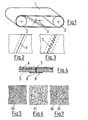
- Fig. 1 eine perspektivische Ansicht eines endlosen Schleifbandes,
- Fig. 2 und 3 zwei Draufsichten unterschiedlich gestalteter Verbindungsstellen,
- Fig. 4 einen Längsschnitt durch eine Verbindungsstelle,
- Fig. 5, 6 und 7 Draufsichten auf wirrfaserverstärkte Kunstharzbänder,
- Fig. 8 und 9 Querschnitte durch unterschiedliche Ausführungsformen solcher Kunstharzbänder und
- Fig. 10 und 11 Längsschnitte durch unterschiedliche Ausführungsformen von Verbindungsstellen.
- 1 is a perspective view of an endless grinding belt,
- 2 and 3 two plan views of differently designed connection points,
- 4 shows a longitudinal section through a connection point,
- 5, 6 and 7 top views of fiber reinforced synthetic resin tapes,
- 8 and 9 cross sections through different embodiments of such synthetic resin tapes and
- 10 and 11 are longitudinal sections through different embodiments of connection points.
Das Schleifband 1, das über Umlenkrollen 2 läuft, ist aus dem ursprünglich gestreckten Zustand durch Verbindung seiner Enden im Bereich der Verbindungsstelle 3 endlos. Die Verbindungsstelle 3 verläuft schräg in einem Winkel 4 gegenüber der Schleifbandquerrichtung.The grinding belt 1, which runs over
Gemäß Fig. 2 bzw.3 kann die Fuge 7 der Verbindungsstelle geradlinig oder nicht geradlinig verlaufen; gezeigt ist in Fig. 3 eine Wellenschnittverbindung.According to FIGS. 2 and 3, the
Gemäß Fig. 4 besteht das Schleifband aus der zugfesten, flexiblen Unterlage 5 und dem Schleifkornbelag 6. Bei 7 erkennt man die Fuge zwischen den zu verbindenden Bandenden.4, the sanding belt consists of the tensile,
Die Verbindung wird vermittelt durch das Kunstharzband 8, das mit den benachbarten Rändern 9 der Schleifbandrückseite beispielsweise zur Klebung verbunden ist.The connection is mediated by the
Das Kunstharzband 8 enthält Verstärkungsfasern, die kurz gehackt sein können, wie dies bei 10 in Fig. 5 schematisch (wenn auch viel zu grob) dargestellt ist, oder auch sehr lang sein können, wie dies Fig. 6 bei 11 veranschaulicht. Die Verstärkungsfasern können aber auch aus kurzen bis langen Fasern 10,11 gemischt sein, wie dies in Fig. 7 gezeigt ist. Gemäß Fig. 8 können die Fasern 10,11 gleichmäßig über den gesamten Querschnitt des übertrieben dick gezeichneten Kunstharzbandes 8 verteilt sein. Gemäß Fig. 9 können sie aber auch eine höhere Konzentration, insbesondere schichtförmig, in der Nähe derjenigen Oberfläche 12 des Kunstharzbandes aufweisen, die zur Verklebung mit der Rückseite des Schleifbandes bestimmt ist.The
Vorzugsweise sind die Verstärkungsfasern überwiegend in der Ebene des Kunstharzbandes orientiert, was sich beispielsweise durch Dehnung des Bandes nach dem Gießen in Längs- und/oder Querrichtung bewerkstelligen läßt.The reinforcing fibers are preferably predominantly oriented in the plane of the synthetic resin tape, which can be accomplished, for example, by stretching the tape in the longitudinal and / or transverse direction after casting.
Wenn die Fasern 10, 11 gemäß Fig. 10 über die Oberfläche 12 hinausstehen oder mindestens teilweise in dieser frei liegen, können sie eine innige Verbindung mit der Bindemittelschicht 13 eingehen, die in dem dargestellten Beispiel zwischen der Rückseite der Schleifbandunterlage 5 und dem Kunstharzband 8 vorgesehen ist.If the
In dem Beispiel gemäß Fig. 11 ist das Kunstharzband 14 in die Vertiefung eingeformt, die durch keilförmige Anschrägung der Ränder 15 der zu verbindenden Schleifbandenden geformt wurde.In the example according to FIG. 11, the
Claims (15)
Applications Claiming Priority (3)
| Application Number | Priority Date | Filing Date | Title |
|---|---|---|---|
| DE19833340432 DE3340432A1 (en) | 1983-11-09 | 1983-11-09 | Grinding belt having a connecting point bridged over by a synthetic resin belt |
| DE3340432 | 1983-11-09 | ||
| PCT/EP1985/000221 WO1986006671A1 (en) | 1985-05-13 | 1985-05-13 | Abrasive belt with bonded splice |
Publications (2)
| Publication Number | Publication Date |
|---|---|
| EP0142140A2 true EP0142140A2 (en) | 1985-05-22 |
| EP0142140A3 EP0142140A3 (en) | 1985-06-19 |
Family
ID=25815469
Family Applications (1)
| Application Number | Title | Priority Date | Filing Date |
|---|---|---|---|
| EP84113528A Withdrawn EP0142140A3 (en) | 1983-11-09 | 1984-11-09 | Abrasive belt with a junction reinforced with a synthetic resin strip |
Country Status (1)
| Country | Link |
|---|---|
| EP (1) | EP0142140A3 (en) |
Cited By (12)
| Publication number | Priority date | Publication date | Assignee | Title |
|---|---|---|---|---|
| EP0213353A1 (en) * | 1985-07-24 | 1987-03-11 | Norddeutsche Schleifmittel-Industrie Christiansen & Co. (GmbH & Co.) | Abrasive belt with transwerse connection |
| FR2625943A1 (en) * | 1988-01-14 | 1989-07-21 | Jouffray Jean Claude | Method for producing composite belts, and composite belts obtained |
| EP0529833A1 (en) * | 1991-08-06 | 1993-03-03 | Minnesota Mining And Manufacturing Company | Endless coated abrasive article |
| FR2699417A1 (en) * | 1992-12-17 | 1994-06-24 | Skid Sa | Endless belt with different abrasives to sand ski |
| WO1995022434A1 (en) * | 1994-02-22 | 1995-08-24 | Minnesota Mining And Manufacturing Company | Coated abrasives and methods of making same |
| US5573619A (en) * | 1991-12-20 | 1996-11-12 | Minnesota Mining And Manufacturing Company | Method of making a coated abrasive belt with an endless, seamless backing |
| US5578096A (en) * | 1995-08-10 | 1996-11-26 | Minnesota Mining And Manufacturing Company | Method for making a spliceless coated abrasive belt and the product thereof |
| US5584897A (en) * | 1994-02-22 | 1996-12-17 | Minnesota Mining And Manufacturing Company | Method for making an endless coated abrasive article |
| US5681612A (en) * | 1993-06-17 | 1997-10-28 | Minnesota Mining And Manufacturing Company | Coated abrasives and methods of preparation |
| US6406577B1 (en) | 1991-12-20 | 2002-06-18 | 3M Innovative Properties Company | Method of making abrasive belt with an endless, seamless backing |
| US6406576B1 (en) | 1991-12-20 | 2002-06-18 | 3M Innovative Properties Company | Method of making coated abrasive belt with an endless, seamless backing |
| US7134953B2 (en) | 2004-12-27 | 2006-11-14 | 3M Innovative Properties Company | Endless abrasive belt and method of making the same |
Citations (5)
| Publication number | Priority date | Publication date | Assignee | Title |
|---|---|---|---|---|
| FR928656A (en) * | 1943-05-17 | 1947-12-04 | Minnesota Mining & Mfg | Improvements to abrasive products and method of manufacturing a sheet product coated with endless abrasive |
| FR1154067A (en) * | 1956-01-31 | 1958-04-02 | Minnesota Mining & Mfg | Joint and assembly method |
| US3154897A (en) * | 1961-11-27 | 1964-11-03 | Minnesota Mining & Mfg | Spliced coated abrasive belt |
| FR2075760A5 (en) * | 1970-01-20 | 1971-10-08 | Fabriksaktiebolaget Eka | |
| FR2279991A1 (en) * | 1974-07-23 | 1976-02-20 | Minnesota Mining & Mfg | POLYESTER JUNCTION TAPES AND THEIR MANUFACTURING PROCESS |
-
1984
- 1984-11-09 EP EP84113528A patent/EP0142140A3/en not_active Withdrawn
Patent Citations (5)
| Publication number | Priority date | Publication date | Assignee | Title |
|---|---|---|---|---|
| FR928656A (en) * | 1943-05-17 | 1947-12-04 | Minnesota Mining & Mfg | Improvements to abrasive products and method of manufacturing a sheet product coated with endless abrasive |
| FR1154067A (en) * | 1956-01-31 | 1958-04-02 | Minnesota Mining & Mfg | Joint and assembly method |
| US3154897A (en) * | 1961-11-27 | 1964-11-03 | Minnesota Mining & Mfg | Spliced coated abrasive belt |
| FR2075760A5 (en) * | 1970-01-20 | 1971-10-08 | Fabriksaktiebolaget Eka | |
| FR2279991A1 (en) * | 1974-07-23 | 1976-02-20 | Minnesota Mining & Mfg | POLYESTER JUNCTION TAPES AND THEIR MANUFACTURING PROCESS |
Cited By (18)
| Publication number | Priority date | Publication date | Assignee | Title |
|---|---|---|---|---|
| AU574929B2 (en) * | 1985-07-24 | 1988-07-14 | Hermes - Schleifmittel GmbH & Co. | Abrasive belt and joint thereof |
| EP0213353A1 (en) * | 1985-07-24 | 1987-03-11 | Norddeutsche Schleifmittel-Industrie Christiansen & Co. (GmbH & Co.) | Abrasive belt with transwerse connection |
| FR2625943A1 (en) * | 1988-01-14 | 1989-07-21 | Jouffray Jean Claude | Method for producing composite belts, and composite belts obtained |
| US5575873A (en) * | 1991-08-06 | 1996-11-19 | Minnesota Mining And Manufacturing Company | Endless coated abrasive article |
| EP0529833A1 (en) * | 1991-08-06 | 1993-03-03 | Minnesota Mining And Manufacturing Company | Endless coated abrasive article |
| US5573619A (en) * | 1991-12-20 | 1996-11-12 | Minnesota Mining And Manufacturing Company | Method of making a coated abrasive belt with an endless, seamless backing |
| US6406577B1 (en) | 1991-12-20 | 2002-06-18 | 3M Innovative Properties Company | Method of making abrasive belt with an endless, seamless backing |
| US5609706A (en) * | 1991-12-20 | 1997-03-11 | Minnesota Mining And Manufacturing Company | Method of preparation of a coated abrasive belt with an endless, seamless backing |
| US6406576B1 (en) | 1991-12-20 | 2002-06-18 | 3M Innovative Properties Company | Method of making coated abrasive belt with an endless, seamless backing |
| US6066188A (en) * | 1991-12-20 | 2000-05-23 | Minnesota Mining And Manufacturing Company | Coated abrasive belt with an endless seamless backing and method of preparation |
| FR2699417A1 (en) * | 1992-12-17 | 1994-06-24 | Skid Sa | Endless belt with different abrasives to sand ski |
| US5681612A (en) * | 1993-06-17 | 1997-10-28 | Minnesota Mining And Manufacturing Company | Coated abrasives and methods of preparation |
| US5924917A (en) * | 1993-06-17 | 1999-07-20 | Minnesota Mining And Manufacturing Company | Coated abrasives and methods of preparation |
| WO1995022434A1 (en) * | 1994-02-22 | 1995-08-24 | Minnesota Mining And Manufacturing Company | Coated abrasives and methods of making same |
| US5584897A (en) * | 1994-02-22 | 1996-12-17 | Minnesota Mining And Manufacturing Company | Method for making an endless coated abrasive article |
| US5578096A (en) * | 1995-08-10 | 1996-11-26 | Minnesota Mining And Manufacturing Company | Method for making a spliceless coated abrasive belt and the product thereof |
| US5830248A (en) * | 1995-08-10 | 1998-11-03 | Minnesota Mining & Manufacturing Company | Method for making a spliceless coated abrasive belt |
| US7134953B2 (en) | 2004-12-27 | 2006-11-14 | 3M Innovative Properties Company | Endless abrasive belt and method of making the same |
Also Published As
| Publication number | Publication date |
|---|---|
| EP0142140A3 (en) | 1985-06-19 |
Similar Documents
| Publication | Publication Date | Title |
|---|---|---|
| EP0106249B1 (en) | Plastic material leafsprings and method for their manufacture | |
| DE2046432B2 (en) | Process for the production of fiber-reinforced components | |
| EP0603352A1 (en) | Plastic-composite profiled girder, in particular a wing spar for aircraft and for wind-turbine rotors | |
| DE2452589A1 (en) | ENDLESS, FLEXIBLE ABRASIVE BELT AND METHOD FOR ITS MANUFACTURING | |
| DE2101793A1 (en) | Endless sanding belt and a process for its manufacture | |
| EP0142140A2 (en) | Abrasive belt with a junction reinforced with a synthetic resin strip | |
| DE2757965B2 (en) | Thrust transmission element and method for its production | |
| DE4208812A1 (en) | Lightweight sandwich structure mfr. - by fusing thermoplastic core and facing layers together at mating faces while in molten state | |
| DE2610915A1 (en) | ELEMENT FOR INTRODUCING TENSIONING FORCE IN FIBER-REINFORCED PLASTIC PARTS | |
| WO1999006651A1 (en) | Flat strip lamella for reinforcing building components and method for placing a flat strip lamella on a component | |
| EP0082321B1 (en) | Flexible fibre-reinforced plastic spring and press for its manufacture | |
| EP0573039B1 (en) | Fibre mats containing a binding agent made from cellulosic and ligno-cellulosic fibres | |
| EP0956193B1 (en) | Thermoplastically deformable composite body | |
| DE3640208C2 (en) | ||
| DE2226803A1 (en) | Connection device for conveyor belts | |
| DE3003537A1 (en) | Laminar construction ski - has intermediate plastics layer rendered adhesive only on heating | |
| DE60130245T2 (en) | BELTS | |
| DE3340432A1 (en) | Grinding belt having a connecting point bridged over by a synthetic resin belt | |
| EP0697953A1 (en) | Weldable drawn plastic strip and structures produced from such strip | |
| DE2236479A1 (en) | Foam core bonding - with drillings carrying glass fibre rovings | |
| WO1986006671A1 (en) | Abrasive belt with bonded splice | |
| EP0031420B1 (en) | Method of making a junction in conveyor belts or the like, and connecting plate for such a junction | |
| DE3238266C2 (en) | Method and apparatus for connecting the ends of a fiber-reinforced plastic belt | |
| DE1780071A1 (en) | Repair patch for pneumatic tires | |
| DE69915032T2 (en) | METHOD FOR PRODUCING A SANDWICH ELEMENT AND CORE MATERIAL THEREFOR |
Legal Events
| Date | Code | Title | Description |
|---|---|---|---|
| PUAI | Public reference made under article 153(3) epc to a published international application that has entered the european phase |
Free format text: ORIGINAL CODE: 0009012 |
|
| PUAL | Search report despatched |
Free format text: ORIGINAL CODE: 0009013 |
|
| AK | Designated contracting states |
Designated state(s): AT BE CH DE FR GB IT LI LU NL SE |
|
| AK | Designated contracting states |
Designated state(s): AT BE CH DE FR GB IT LI LU NL SE |
|
| 17P | Request for examination filed |
Effective date: 19850531 |
|
| 17Q | First examination report despatched |
Effective date: 19860516 |
|
| R17C | First examination report despatched (corrected) |
Effective date: 19870205 |
|
| STAA | Information on the status of an ep patent application or granted ep patent |
Free format text: STATUS: THE APPLICATION IS DEEMED TO BE WITHDRAWN |
|
| 18D | Application deemed to be withdrawn |
Effective date: 19870818 |
|
| RIN1 | Information on inventor provided before grant (corrected) |
Inventor name: TOILLIE, EBERHARD, DIPL.-ING. |