EP0142095A2 - Accumulator-dehydrator assembly for an air conditioning system - Google Patents
Accumulator-dehydrator assembly for an air conditioning system Download PDFInfo
- Publication number
- EP0142095A2 EP0142095A2 EP84113010A EP84113010A EP0142095A2 EP 0142095 A2 EP0142095 A2 EP 0142095A2 EP 84113010 A EP84113010 A EP 84113010A EP 84113010 A EP84113010 A EP 84113010A EP 0142095 A2 EP0142095 A2 EP 0142095A2
- Authority
- EP
- European Patent Office
- Prior art keywords
- accumulator
- set forth
- perforated plate
- canister
- outlet
- Prior art date
- Legal status (The legal status is an assumption and is not a legal conclusion. Google has not performed a legal analysis and makes no representation as to the accuracy of the status listed.)
- Granted
Links
Images
Classifications
-
- F—MECHANICAL ENGINEERING; LIGHTING; HEATING; WEAPONS; BLASTING
- F25—REFRIGERATION OR COOLING; COMBINED HEATING AND REFRIGERATION SYSTEMS; HEAT PUMP SYSTEMS; MANUFACTURE OR STORAGE OF ICE; LIQUEFACTION SOLIDIFICATION OF GASES
- F25B—REFRIGERATION MACHINES, PLANTS OR SYSTEMS; COMBINED HEATING AND REFRIGERATION SYSTEMS; HEAT PUMP SYSTEMS
- F25B43/00—Arrangements for separating or purifying gases or liquids; Arrangements for vaporising the residuum of liquid refrigerant, e.g. by heat
- F25B43/006—Accumulators
-
- F—MECHANICAL ENGINEERING; LIGHTING; HEATING; WEAPONS; BLASTING
- F25—REFRIGERATION OR COOLING; COMBINED HEATING AND REFRIGERATION SYSTEMS; HEAT PUMP SYSTEMS; MANUFACTURE OR STORAGE OF ICE; LIQUEFACTION SOLIDIFICATION OF GASES
- F25B—REFRIGERATION MACHINES, PLANTS OR SYSTEMS; COMBINED HEATING AND REFRIGERATION SYSTEMS; HEAT PUMP SYSTEMS
- F25B2400/00—General features or devices for refrigeration machines, plants or systems, combined heating and refrigeration systems or heat-pump systems, i.e. not limited to a particular subgroup of F25B
- F25B2400/03—Suction accumulators with deflectors
-
- F—MECHANICAL ENGINEERING; LIGHTING; HEATING; WEAPONS; BLASTING
- F25—REFRIGERATION OR COOLING; COMBINED HEATING AND REFRIGERATION SYSTEMS; HEAT PUMP SYSTEMS; MANUFACTURE OR STORAGE OF ICE; LIQUEFACTION SOLIDIFICATION OF GASES
- F25B—REFRIGERATION MACHINES, PLANTS OR SYSTEMS; COMBINED HEATING AND REFRIGERATION SYSTEMS; HEAT PUMP SYSTEMS
- F25B43/00—Arrangements for separating or purifying gases or liquids; Arrangements for vaporising the residuum of liquid refrigerant, e.g. by heat
- F25B43/003—Filters
-
- Y—GENERAL TAGGING OF NEW TECHNOLOGICAL DEVELOPMENTS; GENERAL TAGGING OF CROSS-SECTIONAL TECHNOLOGIES SPANNING OVER SEVERAL SECTIONS OF THE IPC; TECHNICAL SUBJECTS COVERED BY FORMER USPC CROSS-REFERENCE ART COLLECTIONS [XRACs] AND DIGESTS
- Y10—TECHNICAL SUBJECTS COVERED BY FORMER USPC
- Y10S—TECHNICAL SUBJECTS COVERED BY FORMER USPC CROSS-REFERENCE ART COLLECTIONS [XRACs] AND DIGESTS
- Y10S210/00—Liquid purification or separation
- Y10S210/06—Dehydrators
Definitions
- This invention relates to air conditioning systems and particularly to air conditioning systems for automobiles and the like.
- Such air conditioning compressors are designated to operate on gaseous refrigerant only and include an accumulator that receives liquid gas and gaseous refrigerant from the evaporator and seperates the liquid and gaseous refrigerant allowing only the gaseous refrigerant to enter the compressor.
- One way that has been used to remove moisture is to provide desiccant in cloth bags in the liquid refrigerant in the accumulator to adsorb moisture from the liquid. Although such a method is simple and inexpensive, it does not efficiently remove moisture since the desiccant absorbs much less moisture from liquid than the vaporized refrigerant and there is no assurance that the gaseous refrigerant entering the compressor has come into contact with the desiccant.
- an accumulator-dehydrator assembly which is effective to remove the moisture, utilizes a minimum number of parts, is easy to assemble, utilizes low cost materials, and is easy to fill with dessicant.
- the accumulator-dehydrator assembly for an air conditioning system comprises an accumulator housing defining an enclosed chamber including an inlet and an outlet in the upper end and a refrigerant and oil accumulator in the lower end and a vapor drier canister assembly comprising a one-piece plastic body defining a closed top wall, a closed side wall and an open bottom.
- the canister includes an integral outlet projecting into and sealingly engaging the outlet of the housing.
- a vapor filter is associated with the outlet of the canister such that refrigerant flows through the filter before passing through the outlet.
- a perforated plate with a felt pad is provided in the bottom of the canister for holding desiccant within said canister.
- a refrigerant and oil tube is mounted externally of the canister and has a lower end extending to the bottom of the chamber of the accumulator housing and has an upper end extending into the outlet of the canister.
- a plastic filter is associated with the lower end of the tube. Spring means yieldingly urges the perforated bottom plate upwardly.
- the canister has a desiccant filling opening in the side wall thereof, and interengaging means between the bottom plate and the canister for holding said bottom plate in a position such that desiccant can be introduced into the canister after which the bottom plate is released to hold the desiccant in the canister.
- an air conditioning system is shown schematically and comprises a compressor 10 which delivers refrigerant to a condensor 11 and, in turn, to an expander 12 and an evaporator 13 back to the compressor 10.
- the accumulator-dehydrator assembly 15 embodying the invention is provided between the evaporator 13 and compressor 10 and fuctions to remove the moisture from the gaseous refrigerant.
- the accumulator-dehydrator assembly 15 comprises a housing 16 that is entirely enclosed to define an accumulator chamber 17 for the liquid refrigerant at the lower end.
- the housing 16 includes axially aligned tubes forming an inlet 18 and an outlet 19.
- the accumulator-dehydrator assembly 15 further comprises a vapor drier canister 20 including a liquid refrigerant.
- An oil tube 21 is mounted externally of the assembly 20 with the upper end of the tube 21 extending into an integral tube-like outlet 22 of the canister 20 and the lower end of the tube 21 extending into a liquid filter 24 submerged in the liquid refrigerant.
- the canister 20 comprises a one-piece body 23 made of plastic such as polypropylene.
- the body 23 comprises two molded halves 23a, 23b (Fig. 5) joined by an integral hinge 39 and brought together, as presently described, to define a closed top wall 25 (Fig. 1), a closed side wall 26, an open bottom and the integral outlet 22 that projects into the outlet 19 of the accumulator housing 16 and sealingly engages the outlet 19 by use of an O-ring 27.
- the canister 20 further includes, at its bottom, a perforated plate 28 that is yieldingly urged upwardly by a spring 29 to press desiccant D upwardly.
- the perforated plate 28 includes a felt pad 32 overlying and attached thereto as by rivets.
- the felt pad 32 provides little restriction to the gas flow and functions to prevent particles of the desiccant D from falling through the holes in the perforated plate 28, when there are vibrations so that the supply of desiccant is not depleted.
- the spring 29 is interposed between the perforated plate 28 and a retainer ring 30, integral portions 30a thereof being crimped over the bottom of the side wall 26 at circumferentially spaced points.
- the canister 20 is also formed with a desiccant filler opening 31 in the side wall 26.
- the canister 20 is inverted and the perforated plate 28 is held in position below the filler opening 31 (FIG. 2).
- the perforated plate 28 includes a peripheral flange 33 having axial tabs 34 that extend through openings in the retainer ring 30 and are bent inwardly as shown in FIGS. 2 and 3 to retain the perforated plate 28 below the filler opening 31.
- desiccant D can be introduced through the filler opening 31. Thereafter the tabs 34 are straightened so that the perforated plate 28 is released permitting the spring 29 to urge the perforated plate 28 against the desiccant D.
- a filter 35 is provided with a further peripheral flange 36 that telescopes over an annular wall 37 on the outlet 22. Vapor or gaseous refrigerant passes downwardly from the inlet 18, then upwardly through the desiccant D and through the filter 35 to the outlet 22. Filter 35 has mesh or foraminous walls 38 which function as a filter medium.
- the body 23 is molded as one piece comprising two halves 23a, 23b joined by an integral hinge 39.
- the filter 35 is positioned on the annular wall 37 and the two halves 23a, 23b are brought together.
- Ribs 41a and grooves 41b may be provided to facilitate alignment and engagement of the two halves 23a and 23b by forming a tongue and groove joint which renders the gap at the joined edges so small that particles of desiccant D cannot pass.
- the joined edges may be fused ultrasonically.
- the side wall 26 includes a plurality of ribs or projections 40 extending inwardly into contact with the filter 35 to hold same in position.
- the subassembly of retainer ring 30, perforated plate 28, felt pad 32 and spring 29, with tabs 34 extending through ring 30 and bent over is placed on the open end of the body 23 and attached thereto by crimping the ring 30 over the end of the canister as at 30a.
- Each stop 50 is formed by a further tab in the wall of the body 23.
- the tab is connected at its base to the wall and includes a transverse wall 51 and a ramp 52 inclined upwardly and radially inwardly (Fig. 13) so that, as the flange 33 or perforated plate 28 is moved upwardly, it will move along the ramp 52 pushing the stops 50 outwardly and snap over the wall 51.
- the stops 50 will move radially inwardly under flange 33 to prevent axially downward movement of the perforated plate 28.
- the refrigerant and oil tube 21 is made of one-piece metal such as steel and includes an integral orifice 42 at the upper end, a collar 43 spaced from the upper end and a flattened portion 44 intermediate the ends of tha tube 21.
- the collar 43 is an integral portion of the tube 21, the wall thereof being deformed radially outwardly, and engages the outer wall of the outlet 22.
- the flattened portion 44 engages a notch 45 in the ring 30 to hold the tube 21 in position externally of the body 23.
- a tab 46 on the perforated plate 28 initially extends vertically and axially yet is bent over to a horizontal transverse position (FIGS. 2, 4) to retain the tube 21.
- the liquid filter 24 is press fitted on the lower end of the tube 21.
- the collar 43 of the tube 21 serves two functions when it engages the outside wall of the tube 22. First it locates the orifice 42 in the proper position along the inner wall of the outlet 22 to insure that the outlet flow of gaseous refrigerant causes sufficient venturi effect to draw oil and refrigerant droplets up the tube 21 and through the orifice 42. Secondly, it acts as a stop in conduction with the stop formed by the flattened portion 44 of the tube in the bottom member to hold the tube 21 in the proper vertical position.
- filter 24 comprises a hollow plastic body 47 having foraminous or mesh walls 48 so that the liquid must flow through such filter medium to pass upwardly into the tube 21.
- the hollow body 47 is molded in one piece to define two halves joined by an integral hinge such that when the halves are brought together and joined by fusion or bonding on the remaining edges, the hollow body is defined.
- an accumulator-dehydrator assembly 15 that is easy to manufacture and assemble, low in cost, and utilizes a minimum number of parts.
Abstract
Description
- This invention relates to air conditioning systems and particularly to air conditioning systems for automobiles and the like.
- With the increased use of air conditioners in automobiles, it has been found that system failures may occur because of the circulation of moisture in the refrigerant that adversely affects all components of the system but is especially damaging to the close tolerance components of the compressor. As a result increased repair costs and maintenance may be required.
- Such air conditioning compressors are designated to operate on gaseous refrigerant only and include an accumulator that receives liquid gas and gaseous refrigerant from the evaporator and seperates the liquid and gaseous refrigerant allowing only the gaseous refrigerant to enter the compressor. One way that has been used to remove moisture is to provide desiccant in cloth bags in the liquid refrigerant in the accumulator to adsorb moisture from the liquid. Although such a method is simple and inexpensive, it does not efficiently remove moisture since the desiccant absorbs much less moisture from liquid than the vaporized refrigerant and there is no assurance that the gaseous refrigerant entering the compressor has come into contact with the desiccant.
- In US-PS 4,331,001, it has been proposed to hold the desiccant above the liquid level in the accumulator housing and expose all of the vapor entering the compressor to the desiccant to remove any moisture. Although such a system is effective in removing moisture, it involves many parts requiring difficult assembly.
- Accordingly, among the objectives of the present invention are to provide an accumulator-dehydrator assembly which is effective to remove the moisture, utilizes a minimum number of parts, is easy to assemble, utilizes low cost materials, and is easy to fill with dessicant.
- In accordance with the invention, the accumulator-dehydrator assembly for an air conditioning system comprises an accumulator housing defining an enclosed chamber including an inlet and an outlet in the upper end and a refrigerant and oil accumulator in the lower end and a vapor drier canister assembly comprising a one-piece plastic body defining a closed top wall, a closed side wall and an open bottom. The canister includes an integral outlet projecting into and sealingly engaging the outlet of the housing.
- A vapor filter is associated with the outlet of the canister such that refrigerant flows through the filter before passing through the outlet. A perforated plate with a felt pad is provided in the bottom of the canister for holding desiccant within said canister. A refrigerant and oil tube is mounted externally of the canister and has a lower end extending to the bottom of the chamber of the accumulator housing and has an upper end extending into the outlet of the canister. A plastic filter is associated with the lower end of the tube. Spring means yieldingly urges the perforated bottom plate upwardly. The canister has a desiccant filling opening in the side wall thereof, and interengaging means between the bottom plate and the canister for holding said bottom plate in a position such that desiccant can be introduced into the canister after which the bottom plate is released to hold the desiccant in the canister.
- Description of the drawings:
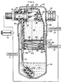
- FIG. 1 is a part sectional partly diagrammatic view of an air conditioning system embodying the invention;
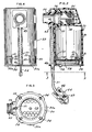
- FIG. 2 is a vertical sectional view through a vapor drier canister assembly embodying the invention;
- FIG. 3 is a fragmentary bottom plan view of the vapor drier canister assembly taken along the line 3-3 in FIG. 2;
- FIG. 4 is a fragmentary side elevational view of the vapor drier canister assembly;
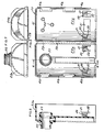
- FIG. 5 is an elevational view of the canister prior to assembly;
- FIG. 6 is a fragmentary sectional view taken along the line 6-6 in FIG. 5;
- FIG. 7 is a top plan view of the portion shown in FIG.5;
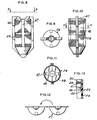
- FIG. 8 is an elevational view of the liquid filter used in the system;
- FIG. 9 is a top plan view taken along the line 9-9 in FIG. 8;
- FIG. 10 is a side elevational view of the liquid filter shown in FIG. 8;
- FIG. 11 is a sectional view taken along the line 11-11 in FIG. 10;
- FIG. 12 is a top plan view of the liquid filter prior to assembly;
- FIG. 13 is a fragmentary sectional view on an enlarged scale taken along the line 13-13 in FIG. 1.
- Referring to FIG. 1, an air conditioning system is shown schematically and comprises a
compressor 10 which delivers refrigerant to a condensor 11 and, in turn, to anexpander 12 and anevaporator 13 back to thecompressor 10. The accumulator-dehydrator assembly 15 embodying the invention is provided between theevaporator 13 andcompressor 10 and fuctions to remove the moisture from the gaseous refrigerant. - Referring to FIGS. 1 and 2, the accumulator-dehydrator assembly 15 comprises a
housing 16 that is entirely enclosed to define an accumulator chamber 17 for the liquid refrigerant at the lower end. Thehousing 16 includes axially aligned tubes forming aninlet 18 and anoutlet 19. The accumulator-dehydrator assembly 15 further comprises avapor drier canister 20 including a liquid refrigerant. Anoil tube 21 is mounted externally of theassembly 20 with the upper end of thetube 21 extending into an integral tube-like outlet 22 of thecanister 20 and the lower end of thetube 21 extending into aliquid filter 24 submerged in the liquid refrigerant. - The
canister 20 comprises a one-piece body 23 made of plastic such as polypropylene. Thebody 23 comprises two moldedhalves 23a, 23b (Fig. 5) joined by anintegral hinge 39 and brought together, as presently described, to define a closed top wall 25 (Fig. 1), a closedside wall 26, an open bottom and theintegral outlet 22 that projects into theoutlet 19 of theaccumulator housing 16 and sealingly engages theoutlet 19 by use of an O-ring 27. - The
canister 20 further includes, at its bottom, aperforated plate 28 that is yieldingly urged upwardly by aspring 29 to press desiccant D upwardly. Theperforated plate 28 includes afelt pad 32 overlying and attached thereto as by rivets. Thefelt pad 32 provides little restriction to the gas flow and functions to prevent particles of the desiccant D from falling through the holes in theperforated plate 28, when there are vibrations so that the supply of desiccant is not depleted. Thespring 29 is interposed between theperforated plate 28 and aretainer ring 30,integral portions 30a thereof being crimped over the bottom of theside wall 26 at circumferentially spaced points. Thecanister 20 is also formed with a desiccant filler opening 31 in theside wall 26. - In order to be filled, the
canister 20 is inverted and theperforated plate 28 is held in position below the filler opening 31 (FIG. 2). To that end, theperforated plate 28 includes aperipheral flange 33 havingaxial tabs 34 that extend through openings in theretainer ring 30 and are bent inwardly as shown in FIGS. 2 and 3 to retain theperforated plate 28 below the filler opening 31. Now desiccant D can be introduced through the filler opening 31. Thereafter thetabs 34 are straightened so that theperforated plate 28 is released permitting thespring 29 to urge theperforated plate 28 against the desiccant D. - A
filter 35 is provided with a furtherperipheral flange 36 that telescopes over anannular wall 37 on theoutlet 22. Vapor or gaseous refrigerant passes downwardly from theinlet 18, then upwardly through the desiccant D and through thefilter 35 to theoutlet 22.Filter 35 has mesh orforaminous walls 38 which function as a filter medium. - As shown in FIGS. 5-7, the
body 23 is molded as one piece comprising twohalves 23a, 23b joined by anintegral hinge 39. For assembling thecanister 20, thefilter 35 is positioned on theannular wall 37 and the twohalves 23a, 23b are brought together. Ribs 41a andgrooves 41b may be provided to facilitate alignment and engagement of the twohalves 23a and 23b by forming a tongue and groove joint which renders the gap at the joined edges so small that particles of desiccant D cannot pass. Furthermore, the joined edges may be fused ultrasonically. Theside wall 26 includes a plurality of ribs orprojections 40 extending inwardly into contact with thefilter 35 to hold same in position. - After the canister halves are brought together and joined and the refrigerant and
oil tube 21 is inserted into theoutlet wall 22, the subassembly ofretainer ring 30, perforatedplate 28, feltpad 32 andspring 29, withtabs 34 extending throughring 30 and bent over, is placed on the open end of thebody 23 and attached thereto by crimping thering 30 over the end of the canister as at 30a. - Self-actuating integral stops 50 functioning as catches are provided on the
side walls 26 of thebody 23 for engaging the lower edge of theperipheral flange 33 of theperforated plate 28 to insure that theplate 28 can not move downwardly on impact due to the weight of the desiccant D overcoming the spring force to expose the filling opening momentarily allowing desiccant to escape. Eachstop 50 is formed by a further tab in the wall of thebody 23. The tab is connected at its base to the wall and includes atransverse wall 51 and aramp 52 inclined upwardly and radially inwardly (Fig. 13) so that, as theflange 33 orperforated plate 28 is moved upwardly, it will move along theramp 52 pushing thestops 50 outwardly and snap over thewall 51. Thestops 50 will move radially inwardly underflange 33 to prevent axially downward movement of theperforated plate 28. - Referring to FIGS. 2 and 4, the refrigerant and
oil tube 21 is made of one-piece metal such as steel and includes anintegral orifice 42 at the upper end, acollar 43 spaced from the upper end and aflattened portion 44 intermediate the ends oftha tube 21. Thecollar 43 is an integral portion of thetube 21, the wall thereof being deformed radially outwardly, and engages the outer wall of theoutlet 22. Theflattened portion 44 engages anotch 45 in thering 30 to hold thetube 21 in position externally of thebody 23. Atab 46 on theperforated plate 28 initially extends vertically and axially yet is bent over to a horizontal transverse position (FIGS. 2, 4) to retain thetube 21. Theliquid filter 24 is press fitted on the lower end of thetube 21. Thecollar 43 of thetube 21 serves two functions when it engages the outside wall of thetube 22. First it locates theorifice 42 in the proper position along the inner wall of theoutlet 22 to insure that the outlet flow of gaseous refrigerant causes sufficient venturi effect to draw oil and refrigerant droplets up thetube 21 and through theorifice 42. Secondly, it acts as a stop in conduction with the stop formed by the flattenedportion 44 of the tube in the bottom member to hold thetube 21 in the proper vertical position. - Referring to FIGS 8 - 12,
filter 24 comprises a hollowplastic body 47 having foraminous or meshwalls 48 so that the liquid must flow through such filter medium to pass upwardly into thetube 21. As shown in FIG. 12, thehollow body 47 is molded in one piece to define two halves joined by an integral hinge such that when the halves are brought together and joined by fusion or bonding on the remaining edges, the hollow body is defined. - It can thus be seen that there has been provided an accumulator-dehydrator assembly 15 that is easy to manufacture and assemble, low in cost, and utilizes a minimum number of parts.
Claims (1)
Priority Applications (1)
| Application Number | Priority Date | Filing Date | Title |
|---|---|---|---|
| DE8787100584T DE3477961D1 (en) | 1983-11-10 | 1984-10-29 | Accumulator-dehydrator assembly for an air conditioning system |
Applications Claiming Priority (2)
| Application Number | Priority Date | Filing Date | Title |
|---|---|---|---|
| US551101 | 1983-11-10 | ||
| US06/551,101 US4509340A (en) | 1983-11-10 | 1983-11-10 | Accumulator-dehydrator assembly for an air conditioning system |
Related Child Applications (3)
| Application Number | Title | Priority Date | Filing Date |
|---|---|---|---|
| EP87100584A Division-Into EP0227639B1 (en) | 1983-11-10 | 1984-10-29 | Accumulator-dehydrator assembly for an air conditioning system |
| EP87100584A Division EP0227639B1 (en) | 1983-11-10 | 1984-10-29 | Accumulator-dehydrator assembly for an air conditioning system |
| EP87100584.9 Division-Into | 1984-10-29 |
Publications (3)
| Publication Number | Publication Date |
|---|---|
| EP0142095A2 true EP0142095A2 (en) | 1985-05-22 |
| EP0142095A3 EP0142095A3 (en) | 1985-07-03 |
| EP0142095B1 EP0142095B1 (en) | 1988-01-13 |
Family
ID=24199863
Family Applications (2)
| Application Number | Title | Priority Date | Filing Date |
|---|---|---|---|
| EP84113010A Expired EP0142095B1 (en) | 1983-11-10 | 1984-10-29 | Accumulator-dehydrator assembly for an air conditioning system |
| EP87100584A Expired EP0227639B1 (en) | 1983-11-10 | 1984-10-29 | Accumulator-dehydrator assembly for an air conditioning system |
Family Applications After (1)
| Application Number | Title | Priority Date | Filing Date |
|---|---|---|---|
| EP87100584A Expired EP0227639B1 (en) | 1983-11-10 | 1984-10-29 | Accumulator-dehydrator assembly for an air conditioning system |
Country Status (7)
| Country | Link |
|---|---|
| US (1) | US4509340A (en) |
| EP (2) | EP0142095B1 (en) |
| JP (1) | JPS60120163A (en) |
| AU (1) | AU566119B2 (en) |
| BR (1) | BR8405711A (en) |
| CA (1) | CA1225938A (en) |
| DE (1) | DE3468732D1 (en) |
Cited By (1)
| Publication number | Priority date | Publication date | Assignee | Title |
|---|---|---|---|---|
| CN103717062A (en) * | 2011-07-27 | 2014-04-09 | 宾昶范 | Livestock temperature sensing device, and system and method using same for remotely diagnosing diseases in livestock |
Families Citing this family (43)
| Publication number | Priority date | Publication date | Assignee | Title |
|---|---|---|---|---|
| US4619673A (en) * | 1985-05-15 | 1986-10-28 | Multiform Desiccants, Inc. | Adsorbent device |
| US4633679A (en) * | 1986-03-17 | 1987-01-06 | General Motors Corporation | Accumulator-dehydrator assembly for an air conditioning system |
| US4698985A (en) * | 1986-03-17 | 1987-10-13 | General Motors Corporation | Accumulator-dehydrator assembly for an air conditioning system |
| JPS62288781A (en) * | 1986-06-03 | 1987-12-15 | Matsushita Electric Ind Co Ltd | Heat carrying accumulator |
| US4768355A (en) * | 1987-01-27 | 1988-09-06 | Ford Motor Company | Accumulator with refrigerant processing cartridge for automotive air conditioning system |
| US4800737A (en) * | 1987-04-17 | 1989-01-31 | Ford Motor Company | Automotive air conditioning system accumulator with refrigerant processing cartridge including evaporator pressure regulator |
| US4838040A (en) * | 1988-03-30 | 1989-06-13 | Freeman Clarence S | Air conditioner dryer utilizing water-encapsulating polymers |
| US4827725A (en) * | 1988-07-05 | 1989-05-09 | Tecumseh Products Company | Suction accumulator with dirt trap |
| US5076071A (en) * | 1990-05-08 | 1991-12-31 | Tecumseh Products Company | Suction accumulator with dirt trap and filter |
| US5179780A (en) * | 1991-11-12 | 1993-01-19 | General Motors Corporation | Universal seamless receiver-dehydrator assembly for an automotive air conditioning system |
| US5201792A (en) * | 1991-12-23 | 1993-04-13 | Ford Motor Company | Accumulator for vehicle air conditioning system |
| US5184479A (en) * | 1991-12-23 | 1993-02-09 | Ford Motor Company | Accumulator for vehicle air conditioning system |
| US5184480A (en) * | 1991-12-23 | 1993-02-09 | Ford Motor Company | Accumulator for vehicle air conditioning system |
| US5245842A (en) * | 1992-05-01 | 1993-09-21 | Fayette Tubular Technology Corporation | Receiver dryer |
| US5580451A (en) * | 1995-05-01 | 1996-12-03 | Automotive Fluid Systems, Inc. | Air conditioning refrigerant fluid dryer assembly |
| US5607637A (en) * | 1995-06-06 | 1997-03-04 | Ibs Filtran Gmbh | Method of manufacturing a transmission fluid filter |
| US5837039A (en) * | 1996-04-17 | 1998-11-17 | Stanhope Products Company | Adsorbent packet for air conditioning accumulators |
| EP0849549B1 (en) * | 1996-12-18 | 2002-04-24 | Showa Denko Kabushiki Kaisha | Accumulator |
| US5814136A (en) * | 1997-04-15 | 1998-09-29 | Stanhope Products Company | Desiccant container |
| US5906112A (en) * | 1997-12-12 | 1999-05-25 | Ford Motor Company | Accumulator for an air conditioning system |
| JP2000088402A (en) * | 1998-07-13 | 2000-03-31 | Showa Alum Corp | Accumulator |
| US6196019B1 (en) | 1997-12-16 | 2001-03-06 | Showa Aluminum Corporation | Accumulator |
| CA2297598C (en) | 2000-01-28 | 2003-12-23 | Ki-Sun Jason Ryu | Accumulator for an air-conditioning system |
| US6311514B1 (en) * | 2000-04-07 | 2001-11-06 | Automotive Fluid Systems, Inc. | Refrigeration accumulator having a matrix wall structure |
| US6418751B1 (en) * | 2000-10-03 | 2002-07-16 | Delphi Technologies, Inc. | Accumulator-dehydrator assembly with anti-bump/venturi effect oil return feature for an air conditioning system |
| US6463757B1 (en) | 2001-05-24 | 2002-10-15 | Halla Climate Controls Canada, Inc. | Internal heat exchanger accumulator |
| US6438972B1 (en) | 2001-08-29 | 2002-08-27 | Automotive Fluid Systems, Inc. | Vessel assembly and related manufacturing method |
| US20050081559A1 (en) * | 2003-10-20 | 2005-04-21 | Mcgregor Ian A.N. | Accumulator with pickup tube |
| US7384455B2 (en) * | 2004-10-05 | 2008-06-10 | Caterpillar Inc. | Filter service system and method |
| US7419532B2 (en) * | 2004-10-05 | 2008-09-02 | Caterpillar Inc. | Deposition system and method |
| US7462222B2 (en) | 2004-10-05 | 2008-12-09 | Caterpillar Inc. | Filter service system |
| US7410529B2 (en) * | 2004-10-05 | 2008-08-12 | Caterpillar Inc. | Filter service system and method |
| US7461519B2 (en) | 2005-02-03 | 2008-12-09 | Halla Climate Control Canada, Inc. | Accumulator with deflector |
| JP4726600B2 (en) * | 2005-10-06 | 2011-07-20 | 三菱電機株式会社 | Refrigeration air conditioner |
| DE102006017071A1 (en) * | 2006-04-10 | 2007-10-11 | Behr Gmbh & Co. Kg | Accumulator with internal heat exchanger e.g. for air conditioning system of motor vehicle, has refrigerant-entrance, refrigerant-Exit by which gaseous refrigerant from inside of accumulator appear |
| US9043243B2 (en) * | 2008-06-02 | 2015-05-26 | Apple Inc. | System and method of generating a media package for ingesting into an on-line downloading application |
| US20110113821A1 (en) * | 2009-11-16 | 2011-05-19 | Chu Henry C | Accumulator for air conditioning system |
| JP5764372B2 (en) * | 2011-04-15 | 2015-08-19 | 株式会社不二工機 | accumulator |
| JP5849909B2 (en) | 2012-09-07 | 2016-02-03 | 株式会社デンソー | accumulator |
| JP6068909B2 (en) * | 2012-10-02 | 2017-01-25 | 株式会社不二工機 | accumulator |
| JP6155005B2 (en) * | 2012-10-12 | 2017-06-28 | 株式会社不二工機 | accumulator |
| DE102014113793A1 (en) * | 2014-02-07 | 2015-08-13 | Halla Visteon Climate Control Corporation | Refrigerant accumulator, in particular for motor vehicle refrigerant circuits |
| US11407274B2 (en) * | 2020-03-12 | 2022-08-09 | Denso International America, Inc | Accumulator pressure drop regulation system for a heat pump |
Citations (5)
| Publication number | Priority date | Publication date | Assignee | Title |
|---|---|---|---|---|
| US3858407A (en) * | 1973-08-14 | 1975-01-07 | Virginia Chemicals Inc | Combination liquid trapping suction accumulator and evaporator pressure regulator device |
| FR2359386A1 (en) * | 1972-05-17 | 1978-02-17 | Virginia Chemicals Inc | SEC DEVICE |
| FR2369510A1 (en) * | 1976-11-02 | 1978-05-26 | Sundstrand Corp | INTEGRATED CONTROL DEVICE FOR HEAT PUMPS |
| US4331001A (en) * | 1981-05-11 | 1982-05-25 | General Motors Corporation | Accumulator-dehydrator assembly for an air conditioning system |
| EP0104750A2 (en) * | 1982-09-23 | 1984-04-04 | Richard John Avery, Jr. | Refrigerant accumulator and charging apparatus and method for vapor-compression refrigeration system |
Family Cites Families (14)
| Publication number | Priority date | Publication date | Assignee | Title |
|---|---|---|---|---|
| US2614694A (en) * | 1949-06-20 | 1952-10-21 | Olaf P Sather | Oil filter cartridge |
| US2689048A (en) * | 1950-01-11 | 1954-09-14 | Milton A Powers | Refillable filter |
| US2792123A (en) * | 1953-05-05 | 1957-05-14 | Erie Meter Systems Inc | Repackable filter cartridge |
| US2953906A (en) * | 1955-05-09 | 1960-09-27 | Lester K Quick | Refrigerant flow control apparatus |
| US3084523A (en) * | 1962-01-30 | 1963-04-09 | Refrigeration Research | Refrigeration component |
| US3618771A (en) * | 1969-09-10 | 1971-11-09 | Akers Inc | Apparatus for drying refrigerant |
| US3595398A (en) * | 1969-11-05 | 1971-07-27 | Fram Corp | Filter assembly having a replaceable filter element |
| US3798921A (en) * | 1973-03-26 | 1974-03-26 | Gen Motors Corp | Air conditioning system with freeze throttling valve |
| US3824802A (en) * | 1973-07-11 | 1974-07-23 | Gen Motors Corp | Control means for accumulator throttling device |
| JPS5151011A (en) * | 1974-10-24 | 1976-05-06 | Virginia Chemicals Inc | EBAHOREETAAATSURYOKUCHOSEIKI OJUSURU SAKUSHONAKYUMUREETAA |
| US4111005A (en) * | 1977-04-07 | 1978-09-05 | General Motors Corporation | Press-on plastic baffle for accumulator-dehydrator |
| US4270934A (en) * | 1978-06-05 | 1981-06-02 | General Motors Corporation | Universal internal tube accumulator |
| US4291548A (en) * | 1980-07-07 | 1981-09-29 | General Motors Corporation | Liquid accumulator |
| US4354362A (en) * | 1980-11-07 | 1982-10-19 | Virginia Chemicals, Inc. | Integral suction line accumulator/filter-drier |
-
1983
- 1983-11-10 US US06/551,101 patent/US4509340A/en not_active Expired - Fee Related
-
1984
- 1984-08-15 CA CA000461078A patent/CA1225938A/en not_active Expired
- 1984-08-24 AU AU32359/84A patent/AU566119B2/en not_active Ceased
- 1984-10-29 EP EP84113010A patent/EP0142095B1/en not_active Expired
- 1984-10-29 DE DE8484113010T patent/DE3468732D1/en not_active Expired
- 1984-10-29 EP EP87100584A patent/EP0227639B1/en not_active Expired
- 1984-10-31 JP JP59230041A patent/JPS60120163A/en active Pending
- 1984-11-08 BR BR8405711A patent/BR8405711A/en unknown
Patent Citations (5)
| Publication number | Priority date | Publication date | Assignee | Title |
|---|---|---|---|---|
| FR2359386A1 (en) * | 1972-05-17 | 1978-02-17 | Virginia Chemicals Inc | SEC DEVICE |
| US3858407A (en) * | 1973-08-14 | 1975-01-07 | Virginia Chemicals Inc | Combination liquid trapping suction accumulator and evaporator pressure regulator device |
| FR2369510A1 (en) * | 1976-11-02 | 1978-05-26 | Sundstrand Corp | INTEGRATED CONTROL DEVICE FOR HEAT PUMPS |
| US4331001A (en) * | 1981-05-11 | 1982-05-25 | General Motors Corporation | Accumulator-dehydrator assembly for an air conditioning system |
| EP0104750A2 (en) * | 1982-09-23 | 1984-04-04 | Richard John Avery, Jr. | Refrigerant accumulator and charging apparatus and method for vapor-compression refrigeration system |
Cited By (1)
| Publication number | Priority date | Publication date | Assignee | Title |
|---|---|---|---|---|
| CN103717062A (en) * | 2011-07-27 | 2014-04-09 | 宾昶范 | Livestock temperature sensing device, and system and method using same for remotely diagnosing diseases in livestock |
Also Published As
| Publication number | Publication date |
|---|---|
| EP0227639A3 (en) | 1987-09-09 |
| JPS60120163A (en) | 1985-06-27 |
| EP0142095A3 (en) | 1985-07-03 |
| CA1225938A (en) | 1987-08-25 |
| BR8405711A (en) | 1985-09-10 |
| AU3235984A (en) | 1985-05-16 |
| EP0227639A2 (en) | 1987-07-01 |
| US4509340A (en) | 1985-04-09 |
| AU566119B2 (en) | 1987-10-08 |
| EP0142095B1 (en) | 1988-01-13 |
| DE3468732D1 (en) | 1988-02-18 |
| EP0227639B1 (en) | 1989-04-26 |
Similar Documents
| Publication | Publication Date | Title |
|---|---|---|
| EP0142095A2 (en) | Accumulator-dehydrator assembly for an air conditioning system | |
| US4291548A (en) | Liquid accumulator | |
| US5038582A (en) | Liquid receiver | |
| US4331001A (en) | Accumulator-dehydrator assembly for an air conditioning system | |
| US4496378A (en) | Accumulator dehydrator | |
| US4474035A (en) | Domed accumulator for automotive air conditioning system | |
| US4276756A (en) | Liquid accumulator | |
| US5289697A (en) | Refrigerant receiver/drier | |
| US5651266A (en) | Drier/accumulator for refrigerant system and method of making same | |
| CA1302718C (en) | Suction accumulator with dirt trap | |
| US5996371A (en) | Adsorbent unit | |
| EP0825399B1 (en) | Accumulator deflector connection and method | |
| JPH06147698A (en) | Accumulator for air-conditioning system and manufacture thereof | |
| US5778697A (en) | Accumulator for refrigeration system | |
| US20060196219A1 (en) | Accumulator with full-flow filtering | |
| JP2002195701A (en) | Liquid receiver | |
| US4633679A (en) | Accumulator-dehydrator assembly for an air conditioning system | |
| US4611750A (en) | Method of assembling an accumulator dehydrator | |
| EP0666456A1 (en) | Refrigerant receiver/drier | |
| US4698985A (en) | Accumulator-dehydrator assembly for an air conditioning system | |
| KR0183418B1 (en) | Receiver driver for a car's airconditioner | |
| US7275392B2 (en) | Internal cage tube bag | |
| US6205809B1 (en) | Self-retaining adsorbent unit | |
| EP0669507A2 (en) | Receiver/dryer | |
| US6257015B1 (en) | Self-retaining adsorbent unit |
Legal Events
| Date | Code | Title | Description |
|---|---|---|---|
| PUAI | Public reference made under article 153(3) epc to a published international application that has entered the european phase |
Free format text: ORIGINAL CODE: 0009012 |
|
| PUAL | Search report despatched |
Free format text: ORIGINAL CODE: 0009013 |
|
| AK | Designated contracting states |
Designated state(s): DE FR GB |
|
| AK | Designated contracting states |
Designated state(s): DE FR GB |
|
| 17P | Request for examination filed |
Effective date: 19850822 |
|
| GRAA | (expected) grant |
Free format text: ORIGINAL CODE: 0009210 |
|
| AK | Designated contracting states |
Kind code of ref document: B1 Designated state(s): DE FR GB |
|
| REF | Corresponds to: |
Ref document number: 3468732 Country of ref document: DE Date of ref document: 19880218 |
|
| ET | Fr: translation filed | ||
| PGFP | Annual fee paid to national office [announced via postgrant information from national office to epo] |
Ref country code: DE Payment date: 19881018 Year of fee payment: 5 |
|
| PLBE | No opposition filed within time limit |
Free format text: ORIGINAL CODE: 0009261 |
|
| STAA | Information on the status of an ep patent application or granted ep patent |
Free format text: STATUS: NO OPPOSITION FILED WITHIN TIME LIMIT |
|
| 26N | No opposition filed | ||
| PG25 | Lapsed in a contracting state [announced via postgrant information from national office to epo] |
Ref country code: GB Effective date: 19891029 |
|
| GBPC | Gb: european patent ceased through non-payment of renewal fee | ||
| PG25 | Lapsed in a contracting state [announced via postgrant information from national office to epo] |
Ref country code: FR Effective date: 19900629 |
|
| PG25 | Lapsed in a contracting state [announced via postgrant information from national office to epo] |
Ref country code: DE Effective date: 19900703 |
|
| REG | Reference to a national code |
Ref country code: FR Ref legal event code: ST |