EP0141396B1 - Access device for positioning a light beam to a desired guide groove of an optical memory apparatus - Google Patents
Access device for positioning a light beam to a desired guide groove of an optical memory apparatus Download PDFInfo
- Publication number
- EP0141396B1 EP0141396B1 EP84113018A EP84113018A EP0141396B1 EP 0141396 B1 EP0141396 B1 EP 0141396B1 EP 84113018 A EP84113018 A EP 84113018A EP 84113018 A EP84113018 A EP 84113018A EP 0141396 B1 EP0141396 B1 EP 0141396B1
- Authority
- EP
- European Patent Office
- Prior art keywords
- signal
- guide groove
- circuit
- light
- light beam
- Prior art date
- Legal status (The legal status is an assumption and is not a legal conclusion. Google has not performed a legal analysis and makes no representation as to the accuracy of the status listed.)
- Expired
Links
- 230000003287 optical effect Effects 0.000 title claims description 70
- 238000001514 detection method Methods 0.000 claims description 12
- 230000004044 response Effects 0.000 claims description 5
- 239000003990 capacitor Substances 0.000 claims description 4
- 230000001131 transforming effect Effects 0.000 claims 1
- 238000000034 method Methods 0.000 description 29
- 238000010586 diagram Methods 0.000 description 18
- 239000011295 pitch Substances 0.000 description 7
- 230000007246 mechanism Effects 0.000 description 6
- 239000002184 metal Substances 0.000 description 5
- 230000002093 peripheral effect Effects 0.000 description 4
- 230000004075 alteration Effects 0.000 description 3
- 238000006243 chemical reaction Methods 0.000 description 3
- 238000010276 construction Methods 0.000 description 3
- 230000000694 effects Effects 0.000 description 3
- 230000006870 function Effects 0.000 description 3
- 230000001681 protective effect Effects 0.000 description 3
- 239000011347 resin Substances 0.000 description 3
- 229920005989 resin Polymers 0.000 description 3
- 239000000758 substrate Substances 0.000 description 3
- 230000001360 synchronised effect Effects 0.000 description 3
- 230000001133 acceleration Effects 0.000 description 2
- 238000013459 approach Methods 0.000 description 2
- 230000008878 coupling Effects 0.000 description 2
- 238000010168 coupling process Methods 0.000 description 2
- 238000005859 coupling reaction Methods 0.000 description 2
- 230000007423 decrease Effects 0.000 description 2
- 230000002708 enhancing effect Effects 0.000 description 2
- 239000011521 glass Substances 0.000 description 2
- 230000007935 neutral effect Effects 0.000 description 2
- 230000008569 process Effects 0.000 description 2
- 238000012545 processing Methods 0.000 description 2
- 230000035945 sensitivity Effects 0.000 description 2
- 238000006757 chemical reactions by type Methods 0.000 description 1
- 239000000470 constituent Substances 0.000 description 1
- 238000011161 development Methods 0.000 description 1
- 230000018109 developmental process Effects 0.000 description 1
- 238000006073 displacement reaction Methods 0.000 description 1
- 238000002474 experimental method Methods 0.000 description 1
- 238000004519 manufacturing process Methods 0.000 description 1
- 239000000463 material Substances 0.000 description 1
- 230000010358 mechanical oscillation Effects 0.000 description 1
- 230000010355 oscillation Effects 0.000 description 1
- 239000004033 plastic Substances 0.000 description 1
- 229920003023 plastic Polymers 0.000 description 1
- 230000010287 polarization Effects 0.000 description 1
- 238000012552 review Methods 0.000 description 1
- 239000004065 semiconductor Substances 0.000 description 1
- 238000004088 simulation Methods 0.000 description 1
- 230000001052 transient effect Effects 0.000 description 1
Images


Classifications
-
- G—PHYSICS
- G11—INFORMATION STORAGE
- G11B—INFORMATION STORAGE BASED ON RELATIVE MOVEMENT BETWEEN RECORD CARRIER AND TRANSDUCER
- G11B7/00—Recording or reproducing by optical means, e.g. recording using a thermal beam of optical radiation by modifying optical properties or the physical structure, reproducing using an optical beam at lower power by sensing optical properties; Record carriers therefor
- G11B7/08—Disposition or mounting of heads or light sources relatively to record carriers
-
- G—PHYSICS
- G11—INFORMATION STORAGE
- G11B—INFORMATION STORAGE BASED ON RELATIVE MOVEMENT BETWEEN RECORD CARRIER AND TRANSDUCER
- G11B7/00—Recording or reproducing by optical means, e.g. recording using a thermal beam of optical radiation by modifying optical properties or the physical structure, reproducing using an optical beam at lower power by sensing optical properties; Record carriers therefor
- G11B7/08—Disposition or mounting of heads or light sources relatively to record carriers
- G11B7/085—Disposition or mounting of heads or light sources relatively to record carriers with provision for moving the light beam into, or out of, its operative position or across tracks, otherwise than during the transducing operation, e.g. for adjustment or preliminary positioning or track change or selection
- G11B7/08505—Methods for track change, selection or preliminary positioning by moving the head
- G11B7/08517—Methods for track change, selection or preliminary positioning by moving the head with tracking pull-in only
-
- G—PHYSICS
- G11—INFORMATION STORAGE
- G11B—INFORMATION STORAGE BASED ON RELATIVE MOVEMENT BETWEEN RECORD CARRIER AND TRANSDUCER
- G11B17/00—Guiding record carriers not specifically of filamentary or web form, or of supports therefor
- G11B17/005—Programmed access to indexed parts of tracks of operating discs, by guiding the disc
-
- G—PHYSICS
- G11—INFORMATION STORAGE
- G11B—INFORMATION STORAGE BASED ON RELATIVE MOVEMENT BETWEEN RECORD CARRIER AND TRANSDUCER
- G11B7/00—Recording or reproducing by optical means, e.g. recording using a thermal beam of optical radiation by modifying optical properties or the physical structure, reproducing using an optical beam at lower power by sensing optical properties; Record carriers therefor
- G11B7/08—Disposition or mounting of heads or light sources relatively to record carriers
- G11B7/085—Disposition or mounting of heads or light sources relatively to record carriers with provision for moving the light beam into, or out of, its operative position or across tracks, otherwise than during the transducing operation, e.g. for adjustment or preliminary positioning or track change or selection
- G11B7/08505—Methods for track change, selection or preliminary positioning by moving the head
- G11B7/08529—Methods and circuits to control the velocity of the head as it traverses the tracks
-
- G—PHYSICS
- G11—INFORMATION STORAGE
- G11B—INFORMATION STORAGE BASED ON RELATIVE MOVEMENT BETWEEN RECORD CARRIER AND TRANSDUCER
- G11B7/00—Recording or reproducing by optical means, e.g. recording using a thermal beam of optical radiation by modifying optical properties or the physical structure, reproducing using an optical beam at lower power by sensing optical properties; Record carriers therefor
- G11B7/08—Disposition or mounting of heads or light sources relatively to record carriers
- G11B7/085—Disposition or mounting of heads or light sources relatively to record carriers with provision for moving the light beam into, or out of, its operative position or across tracks, otherwise than during the transducing operation, e.g. for adjustment or preliminary positioning or track change or selection
- G11B7/0857—Arrangements for mechanically moving the whole head
- G11B7/08582—Sled-type positioners
- G11B7/08588—Sled-type positioners with position sensing by means of an auxiliary system using an external scale
-
- G—PHYSICS
- G11—INFORMATION STORAGE
- G11B—INFORMATION STORAGE BASED ON RELATIVE MOVEMENT BETWEEN RECORD CARRIER AND TRANSDUCER
- G11B7/00—Recording or reproducing by optical means, e.g. recording using a thermal beam of optical radiation by modifying optical properties or the physical structure, reproducing using an optical beam at lower power by sensing optical properties; Record carriers therefor
- G11B7/08—Disposition or mounting of heads or light sources relatively to record carriers
- G11B7/09—Disposition or mounting of heads or light sources relatively to record carriers with provision for moving the light beam or focus plane for the purpose of maintaining alignment of the light beam relative to the record carrier during transducing operation, e.g. to compensate for surface irregularities of the latter or for track following
- G11B7/0901—Disposition or mounting of heads or light sources relatively to record carriers with provision for moving the light beam or focus plane for the purpose of maintaining alignment of the light beam relative to the record carrier during transducing operation, e.g. to compensate for surface irregularities of the latter or for track following for track following only
Definitions
- the present invention relates to an optical memory apparatus according to the precharacterizing part of claim 1.
- Such an optical memory apparatus is known from the GB-A-2 000 612.
- optical disc Invention, an optical memory apparatus called "optical disc” has been proposed wherein a rotary disc, in which a predetermined substrate is vapor-coated with an information recording medium (e.g., a metal film), is irradiated with a laser beam which is fined into a spot of approximately 1 pm in diameter and the irradiation power of which is modulated thereby to thermally provide recesses (called "pits") in the recording medium and to record information, and wherein at playback, a weak laser beam is condensed and projected on the recording medium, and the information is read by utilizing variation in the quantity of reflected light from the pits.
- Such proposal has been made in 'Electronics', Nov. 23, 1978, p. 75, "Ten Billion Bits Fit onto Two Sides of 12-inch disc".
- a typical example of arrangement of the memory apparatus is shown in Figure 1.
- a disc (partly broken away in the illustration of the figure) 3 having a diameter of approximately 30 cm is rotated in the direction of an arrow about a rotary shaft 4 by a driving motor 5.
- An optical head 2, which is constructed of a laser source and an optical system, is carried on a swing arm actuator 1 having been used in a magnetic disc etc. and is driven in the radial direction of the disc 3.
- the disc 3 has its surface covered with a transparent protective film 6 of glass of the like.
- the protective film 6 is further partly broken away, to illustrate pits 12 to be stated later.
- guide grooves On a substrate 11 of glass or plastics, guide grooves (called “tracks") 13 of a concave sectional structure having a certain degree of width and depth are formed by the use of an ultraviolet- setting resin 14 orthe like. Further, a metal film 10 is evaporated on the resin 14, whereupon the protective film 6 is deposited.
- the focused spot of light from the optical head 2 is guided along the guide grooves 13, that is, the light spot tracks the guide grooves 13, and the metal film 10 is dissolved by the light spot so as to form the pits 12.
- a light spot is similarly projected along the guide grooves 13, and the quantity of the resulting reflected light is read.
- signals for controlling the light spot are detected from the quantity of the reflected light.
- the signals for controlling the light spot are, in the main, the two of a focal deviation detecting signal for detecting a focal deviation ascribable to the vertical oscillations of the disc, and a tracking deviation detecting signal for detecting the deviation between the center of the light spot and the center line of the guide groove. All such signals use the quantity of the reflected light from the metal film, namely, the area other than the pits.
- one side of the disc having a diameter of 300 mm is provided with about 50,000 guide grooves, and data to be received per guide groove become about 4,000 bytes.
- each guide groove a plurality of sectors for indicating the limits of the data are provided in the rotational direction of the disc in advance.
- the access operation of looking for one guide groove out of the surface of the disc and finding out one sector on this guide groove is required. That is, there are required the so-called "seek" operation of moving the light spot to a selected guide groove where desired information is recorded or it is to be recorded, and the so-called tracking of maintaining the light spot on the center line of the guide groove with the minimum deviation throughout the period of time during which the information is being read or being recorded.
- the magnetic disc As an apparatus requiring such access operation, there has heretofore been known the magnetic disc. Since, however, the track pitches of the magnetic disc are about 150 pm to 30 pm and are one order to two orders of magnitude greater than the pitches of the guide grooves of the optical disc, positioning based on the same access operation as in the magnetic disc cannot be applied to the optical disc. More specifically, when a magnetic head is brought to a desired track by an actuator (for example, a voice coil type linear motor), a steady state error (an offset from the target position) of about 5-10 pm develops though it differs depending upon the construction and performance of the actuator. It is caused by friction etc. Moreover, in the transient state of the positional control, an overshoot can take place with respect to the target position, and it amounts to about 5 pm.
- an actuator for example, a voice coil type linear motor
- the stop precision is as very low as about 10 pm. Since, as described before, the pitches of the guide grooves of the optical disc are about 1.6 pm at the least for the time being, the positioning of the optical disc is difficult with the access method of the magnetic disc.
- the optical disc does not include a disc and a servo head for positioning. This leads to the problem that the exact position of the optical head cannot be detected.
- the optical memory apparatus known from the GB-A-2 000 612 is concerned with a read only system (only play back operation). Thereby it is always assumed that there are recorded data (informations bits) and therefore there cannot be a coexistence of non-recorded guide grooves and recorded guide grooves.
- the known optical memory apparatus in order to detect an envelope signal the reproduction signal obtained from the recording medium is passed through a high-pass filter and the output signal of this high-pass filter is then detected by an envelope detector.
- An object of the present invention is to solve the problems described above, and to provide an optical memory apparatus being adapted for recording and playing back information and having an access device for positioning a light beam to a desired guide groove on the recording medium.
- the trace 40 of the light spot corresponds to a case where the light spot has passed through a group of eccentric tracks at the maximum speed of eccentricity.
- Individual solid lines represent the variations-with-time of the positions of the tracks in the radial direction of the disc.
- the count value of the passage through the tracks and the number of tracks having been passed are in agreement.
- the trace 41 of the light spot corresponds to a case where the light spot has passed through the group of tracks at a speed lower than the maximum speed of the eccentricity. In this case, the count value of the passage through the tracks does not agree with the number of tracks having been actually passed, but the former is larger.
- the direction in which the light spot passes through the guide groove (track) and the number of the guide grooves which have been passed are detected by the use of a signal indicating the total quantity of reflected light at the passage of the light spot through the guide groove and the tracking deviation signal (tracking signal), and the addition or subtraction of the guide grooves passed is executed in accordance with the direction of the passage, thereby to detect the exact position of the optical head, that is, the light spot.
- the present invention comprises a first actuator which has a movable range extending over a full radius of the disc, and a second actuator which has a minute variable range and which exhibits a high responsibility.
- a positioning precision unattainable with only one actuator is realized by interlocking the two actuators.
- a method of controlling the two actuators becomes a problem.
- the problem is solved in such a way that the movement of the second actuator for high-precision positioning is detected, and that the first actuator for approximate positioning over the full radius of the disc is driven in interlocking with the detected movement.
- Figures 4(a), 4(b) and 4(c) are explanatory diagrams of methods of producing signals expressive of the direction in which the optical head passes through a track, and the passage through the track, in order to exactly detect the position of the optical head from a disc.
- light rays emergent from the light source of the optical head are condensed by an objective (not shown), to form a spot 50 on a metal film 10 through a substrate 11 of the disc and a UV resin 14 forming guide grooves (tracks) 13.
- an objective not shown
- a spot size (a diameter at which an intensity of 1/ e 2 is established) becomes about 1.6 pm. It is assumed that the pitches of the guide grooves made on the disc are 1.6 pm. Then, as the spot moves radially of the disc in the direction of an arrow, a tracking signal 52 expressing the deviation between the center line of the guide groove and the center of the spot varies as shown in Figure 4(b). Regarding the production of this signal, there are a method employing two spots as disclosed in Japanese Laid-open Patent Application No. 49-50954, a method of spot wobble as disclosed in Japanese Laid-open Patent Application No.
- the tracking signal 52 becomes null at the center line of the guide groove, and its sign differs depending upon whether the light spot lies on the right side or the left side of the guide groove (corresponding to the outer peripheral side or the inner peripheral side of the disc).
- total quantity of reflected light denotes the total quantity of light which has passed and arrived through the apertures of a lens having a certain specified numerical aperture, when the reflected light from the disc has been condensed by the lens.
- This sort of light quantity is used for detecting an information signal recorded on the disc.
- the information signal is obtained in such a way that a light beam arriving through the lens aperture is condensed on the light receiving face of a single photodetector and is converted into a photocurrent, that the light beam is projected on a group of photodetectors having a plurality of light receiving faces, photocurrents from the respective photodetectors being summed, or that the photocurrents are converted into voltages, which are added up.
- the resulting signal can be used as the aforementioned signal 51 of the total quantity of reflected light.
- FIG. 5 shows the A.C. component of the total reflected-light quantity signal.
- (b) in the figure shows the tracking signal.
- the variations of the two signals versus a time axis are illustrated as to a case where the light spot has moved from the outer side toward the inner side of the disc, has stopped halfway and has moved in the opposite direction.
- (c) in Figure 5 shows a track signal 90 indicating places in which guide grooves exist. This signal exploits the fact that the total quantity of reflected light decreases in the place where the guide groove exists.
- the signal of the total quantity of reflected light is compared with a certain voltage E i , and a case where the former is smaller than the latter is caused to correspond to the state of logic level "0". Then, when the variation of the signal 90 is observed on the time axis, the fall of the waveform corresponds substantially to that edge of the guide groove at which the spot begins to traverse this guide groove. Therefore, pulses 92 of small time width ((e) in Figure 5) are prepared from the falls. On the other hand, in order to know the direction in which the spot passes through the guide groove, a signal (called “track sign signal”) 91 ((d) in Figure 5) is prepared by comparing the tracking signal 52 with the zero level.
- the direction of the passage through the guide groove can be known by comparing the track sign signal 91 with the timing of the track passage edge signal 92. Accordingly, when it is desired to know the number of the guide grooves through which the light spot has passed when moving from the outer side toward the inner side, the number of pulses of a track passage edge signal 53 ((g) in Figure 5) at the time at which the tracking signal 52 becomes minus, that is, at which the track sign signal 91 becomes a low level, may be counted. The same applies to the movement in the opposite direction.
- An example of a practicable circuit for realizing the operations described above is shown in Figure 6.
- the total reflected-light quantity signal 51 is applied to the (+) terminal of a comparator 92a, and the voltage E, is applied to the (-) terminal thereof, thereby to make the comparison between the total reflected-light quantity signal 51 and the voltage E l .
- An output logic level becomes “1” when the level of the signal 51 is greater than E 1 , and it becomes "0" in the other case.
- the output signal 90 is applied to a monostable multivibrator 94 so as to form the pulses of fixed width from the falls of the signal 90.
- This output signal 92 is applied to one terminal of each of AND circuits 95a and 95b for taking logical products.
- the remaining terminals of the AND circuits 95a and 95b are respectively supplied with the sign signal 91 obtained by applying the tracking signal 52 to a comparator 93b, and a signal obtained by inverting the sign signal 91 by means of an inverter circuit 96.
- the respective AND circuits 95b and 95a deliver a plus direction edge signal 54 ((f) in Figure 5) which generates a pulse each time the light spot passes through the track from the inner side to the outer side, and the minus direction edge signal 53 which generates the pulse each time the light spot passes through the track from the outer side to the inner side.
- an access sign signal 56 indicating the direction of the access is caused to correspond to, for example, the logic level "0" in case of accessing the target track from the outer side toward the inner side.
- a logic circuit consisting of logic elements 97, 98, 99, 100, 101, 102 and 103 selects the plus direction edge signal 54 and applies it to the Up terminal of a counter 104, and it selects the minus direction edge signal 53 and applies it to the Down terminal of the counter 104.
- the counter 104 is loaded with the absolute value 55 of a difference up to the target guide groove located on the inner side.
- the pulse appears in the minus direction edge signal 53 and decreases the content of the counter 104 each time the light spot traverses one guide groove from the outer side toward the inner side.
- the pulse appears in the plus direction edge signal 54 and increases the content of the counter 104.
- the counter 104 delivers the exact absolute value 57 of the remaining guide grooves in the access operation.
- a pulse A which indicates this fact is provided from the BR terminal of the counter 104. From this pulse A, it can be known that the light spot has reached the edge of the target guide groove.
- the absolute value of a speed in the access operation can be known.
- the minus direction edge signal 53 is applied to a frequency-to-voltage converter 105
- the plus direction edge signal 54 is applied to a frequency-to-voltage converter 106.
- p denote the pitch of the guide grooves
- v denote the absolute value of the speed of the passage through the guide groove
- the frequency f of a train of pulses each of which appears at the edge of the guide groove at the passage through this guide groove is given by the following expression:
- the absolute value of the speed at which the light spot passes through the guide groove can be known.
- the direction of the passage can be known from the existence of the pulse of the edge signal 53 or 54.
- the circuit of Figure 7 is a practicable example for performing the operations.
- the output of the frequency-to-voltage converter (hereinbelow, termed "FN converter") 105 or 106 is such that, in correspondence with the sign of passage through each track, the speed of the passage through the track is converted into the analog value in the form of a voltage, this form being convenient for the later speed comparison.
- the outputs of the F/ V converters 105 and 106 have their difference taken by a differential amplifier 107, the output of which is applied to both the input of an inverter circuit 108 and a switching circuit 109.
- the output of the inverter circuit 108 is applied to a switching circuit 110, which is controlled by the inverted signal of the control 56 for controlling the switching circuit 109.
- the outputs of the switching circuits 109 and 110 are combined to form a signal 111 expressive of the absolute value of the speed. More specifically, as regards the access sign signal 56, the access from the inner side toward the outer side is now caused to correspond to logic level "1". In case of the access from the inner side to the outer side, therefore, the FN conversion output of the plus direction edge signal 54 brings the differential output into the + sign.
- the switching circuit 109 turns ON, and this appears as the absolute value signal 111 of the speed.
- the access sign signal 56 is "0" in terms of the logic level. Therefore, the switching circuit 110 is turned ON by the output of an inverter 112 for inverting the access sign signal 56.
- the FN conversion output of the minus direction edge signal 53 brings the output of the differential amplifier 107 into the - sign, but the latter is rendered the ⁇ sign by the inverter circuit 108. This appears as the absolute value signal 111 of the speed.
- the servo system of the positional control is usually designed on the assumption of the performance of a linear operation. This comes from an easy analysis and a simple circuit arrangement. As shown in Figure 4(b), however, the tracking error signal 52 varies sinusoidally as a function of the track position and exhibits a nonlinear characteristic as a control input. In such system, the timing at which the operation of the servo system is started becomes an important factor for the stable operation of the system. Referring to (a) of Figure 8, when the spot has traversed the disc from the inner side to the outer side thereof, to come close to the N-th target guide groove, the tracking error signal 52 varies as illustrated.
- the timing (of the start of the positional control) for executing the stable operation extends, according to experiments, between the peak points of the + and - signs closest to the target point (within ⁇ rr/2 in terms of the phase of the sinusoidal wave). More suitable is a linear region whose point of symmetry is the origin.
- the servo system needs to be operated at an edge part before the passage through the zero point of the target guide groove.
- the positional servo system when the spot approaches the target guide groove from the inner side toward the outer side of the disc, the positional servo system may be turned ON after the spot has passed through the zero point of a guide groove directly preceding to the target guide groove and has passed through the next plus peak point. Conversely, when the spot approaches the target guide groove from the outer side toward the inner side of the disc, the positional servo system is turned ON after the spot has passed through the zero point of the guide groove directly preceding to the target guide groove and has passed through the next minus peak point. Circuits for realizing the above are shown in Figures 9 and 10.
- FIG. 8 shows the tracking error signal 52 at the time at which the spot has approached the target guide groove from the inner side toward the outer side of the disc, a signal 113 indicating linear regions, a signal B indicating the turn-ON of the positional servo system, and a signal 144 indicating the arrival at the target guide groove, respectively.
- the tracking error signal 52 is applied to the + terminal of a comparator 117, the - terminal of which is supplied with a voltage E 2 .
- the level of the voltage E 2 is set at a positive level which is substantially linear to the target point 115 of the tracking error signal 52.
- the output of the comparator 117 is applied to one input terminal of an AND circuit 120, the other input terminal of which is supplied with the access polarity signal 56.
- the tracking error signal 52 is also applied to the - terminal of a comparator 118, the + terminal of which is supplied with a voltage E 3 .
- the level of the voltage E 3 is set at a negative level which is substantially linear to the target point 115 of the tracking error signal 152.
- the output of the comparator 118 is applied to one input of an AND circuit 121, the other input of which is supplied with a signal obtained by inverting the access sign signal 56 by means of an inverter 119.
- the outputs of the AND circuits 121 and 120 are applied to an OR circuit 122 which takes the logical sum thereof.
- the output 113 of the OR circuit 122 becomes the waveform as shown in (b) of Figure 8, when the access sign signal 56 is "1", and it becomes a waveform as shown in (e) of Figure 8, when the access sign signal 56 is "0".
- the fall of a pulsative signal represents the end of the linear region whose center is the target point.
- the linear region of the target guide groove needs to be known.
- the BR output (the signal provided when the counter content 57 has become zero) A of the counter 104, which has been explained with reference to Figure 6, is used.
- the pulses 54 and 53 indicative of the passage through the guide grooves develop at those edge parts of the guide grooves to-be-passed which appear in time precedence. Accordingly, the rise parts of the pulses correspond substantially to the peak points of the tracking error signal. Supposing that the signal A is a pulse signal which rises when the content of the counter 104 has become zero, it is applied to a flip-flop 128 so as to prepare the signal 114 which rises at the rise of the signal A.
- the signal 114 is applied to one input of an AND circuit 123, and the signal 113 is applied to the other input thereof, whereby the linear region of the target guide groove is selected by the signal 114.
- the output of the AND circuit 123 is applied to a trailing edge reaction type (master- slave type) flip-flop 124, to generate a positional control start signal B which rises at the trailing edge of the applied input.
- the signal B can also be formed by the circuit shown in Figure 10.
- the tracking error signal 52 is applied to a switching circuit 125, while it is applied to and inverted by an inverting amplifier 116, the inverted signal entering a switching circuit 126.
- the switching circuit 125 is controlled by the access sign signal 56, and the switching circuit 126 is controlled by a signal obtained by inverting the access sign signal 56 by means of an inverter 119.
- the outputs of the switching circuits 125 and 126 are combined and then applied to the + terminal of a comparator 127.
- the voltage E 2 is applied to the - terminal of the comparator 127.
- the signal 113 in which the fall of the comparator output represents the end of the linear region having the target point as its center is generated.
- the subsequent processing is the same as the operations in Figure 9. In this case, the positive peak level and the negative peak level of the tracking error signal 52 must be substantially equal.
- the circuit of Figure 10 corresponds to a case of processing the first half portion of the circuit of Figure 9 analogously.
- the seek control and the follow-up control are carried out by a single actuator, and an optical head to be placed on the actuator is made light in weight and small in size.
- the optical head can be placed on the arm portion of the swing arm explained with reference to Figure 1.
- the quantity of reflected light detected by the optical head 2 is subjected to photoelectric conversion by a photodetector (not shown), and the resulting electric signal is applied to a tracking error signal generator circuit 201 and a total reflected-light quantity signal generator circuit 200.
- the tracking error signal 52 is obtained from the tracking error signal generator circuit 201, while the total reflected-light quantity signal 51 is obtained from the total reflected-light quantity signal generator circuit 200.
- the tracking error signal 52 and the total reflected-light quantity signal 51 are applied to an edge signal generator circuit 202, which generates the plus direction edge signal 54 and the minus direction edge signal 53, and they are operated and processed therein.
- the arrangement of the edge signal generator circuit 202 has been described in detail in conjunction with Figure 6.
- the plus and minus direction edge signals 54 and 53 are applied to both a differential counter 203 for calculating the difference up to the target guide groove and a velocity detecting circuit 204, which deliver the absolute value signal 57 of the difference up to the target guide groove and the absolute value signal 111 of the velocity respectively.
- the arrangement and operations of the differential counter 203 have been described in detail with reference to Figure 6, while the arrangement and operations of the velocity detecting circuit 204 have been described in detail with reference to Figure 7.
- the absolute value signal 57 of the difference up to the target guide groove is applied to a target velocity curve generator circuit 205.
- the target velocity curve generator circuit 205 delivers the optimum velocity in accordance with the difference up to the target guide groove.
- the optimum velocity is recommended to be proportional to the square root of the difference.
- a table of square roots is stored in a ROM beforehand, and a target velocity signal 206 is delivered digitally in accordance with the absolute value signal 57 of the difference up to the target guide groove.
- the target velocity signal 206 is applied to a D/A (digital-to-analog) converter 207 and is converted into an analog quantity, which is applied to one input of a differential amplifier 308.
- the other input thereof receives the absolute value signal 111 of the velocity from the velocity detecting circuit 204, so that the difference is taken.
- the output of the difference is applied to a sign inversion circuit 209.
- the sign inversion circuit 209 Since the output of the difference of the velocity is an absolute value, the sign inversion circuit 209 performs the operation of affording a sign to the velocity difference in correspondence with the logic level of the access sign signal 56. Accordingly, the output of this circuit becomes the difference between the target velocity and the actual velocity and having the sign.
- This difference enters a seek control/positional control switching circuit 210, which is controlled by the timing signal B for the start of the positional control. More specifically, when the timing signal B is LOW, the seek control is established, and the signal of the velocity difference appears at the output of the switching circuit 210 and drives the swing arm 1 through a swing arm driver circuit 251. When the seek control has ended with the light spot arriving at the target guide groove, the timing signal B becomes HIGH to switch the control to the positional control.
- the tracking error signal 52 is applied to a switching circuit 21.1, which is coupled to a phase compensator circuit 212 under the control of the timing signal B or when this timing signal is "high".
- the output of the phase compensator circuit is applied to an adder circuit 213 along with a jump signal D to be described later, and the applied signals are added therein, the sum being applied to the switching circuit 210.
- the positional control is started by the timing signal B, and the light spot can be stably introduced to the target guide groove.
- the tracking error signal 52 is also applied to a timing signal generator circuit 214 for producing the timing signal B, along with the access sign signal 56 and the signal A.
- the arrangement and operations of the circuit 214 have been described in detail with reference to Figures 9 and 10.
- the target guide groove is tracked by the above operations, and address information stored in the guide groove is read out. Reading means therefor is omitted in the present embodiment.
- the read-out information is transmitted to a controller (not shown), to decide whether or not the particular guide groove is the target guide groove.
- the controller mentioned here is a control unit which controls the whole optical disc apparatus. Usually, it gives instructions or command to the driving unit (having been described in detail in the present invention) which includes the driving mechanism and the driving circuitry required, at the least, for reading and writing data, and it controls the driving unit in order to read or write data.
- the driving unit (having been described in detail in the present invention) which includes the driving mechanism and the driving circuitry required, at the least, for reading and writing data, and it controls the driving unit in order to read or write data.
- the driving unit executes the seek control and the positional control by itself, and begins to read data from the target guide groove or a guide groove close thereto.
- the controller decodes the data to know the address of the guide groove currently read out and to judge the subsequent access procedure.
- the controller transmits as a jump number signal 58, a signal indicative of one guide groove, and a jump sign signal indicative of the direction of jump from the outer side to the inner side of the disc, on the assumption that guide grooves on the disc are recorded spirally from the inner side to the outer side.
- the jump number signal 58 is applied to a jump counter 215.
- the jump counter 215 transmits the sign signal of the jump to a jump signal generator 216, and generates pulses for starting the jump by the number of guide grooves to be jumped, at specified time intervals.
- the jump signal generator 216 Upon receiving the pulses, the jump signal generator 216 produces the driving signal D for executing the jump in accordance with the jump sign signal.
- the details of the jump operation are contained in 'Philips Technical Review', Vol. 33, p. 178, and are omitted here.
- the jump number signal 58 is transmitted from the controller in the manner including the signal indicative of one guide groove to be jumped and the jump sign signal indicative of the direction of the jump from the outer side to the inner side, each time the disc executes one revolution.
- this guide groove differs from the target guide groove
- the light spot is moved to the target guide groove by performing the jump, subject to the condition that the difference between the guide groove current read out and the target guide groove is smaller than a certain set number (for example, 64 or 128).
- the controller transmits the jump number signal 58 which contains the number of guide grooves up to the target guide groove and the direction of the jump. If the difference between the current guide groove and the target guide groove is greater than the certain set value, an access operation including the speed control will be started. This operation is the repetition of the access procedure thus far explained.
- the position of the optical head can be exactly detected without errors attributed to an eccentricity, mechanical vibrations, etc.
- the aforementioned signals at the passage of the light spot through the guide groove are also utilized for the velocity detection, whereby the relative velocity between the light spot and the guide groove can be exactly detected.
- the positioning operation is possible from the rough positioning over the full radius of the disc to the fine positioning of about 0.1 pm.
- a linear motor 314 will be exemplified as the first actuator for the rough positioning.
- the purport of the present invention applies also to other actuators.
- a galvano-mirror 308 or a pivot mirror is employed as the second actuator of high responsibility for the follow-up control within the minute range.
- the disc 3 is rotating in a predetermined direction about the rotary shaft 4.
- An optical head 2' is placed on a movable bed 315, which moves on a base 309 as rollers 310 rotate.
- the movable bed 315 is coupled to a coil 311 through a supporting mechanism 313, and it is driven by the electromagnetic forces of a magnet 312 and current flowing through the coil 311.
- the optical head 2' includes therein an objective 306 which serves to form the light spot on the disc, the galvano-mirror 308 which is means for deflecting the light spot on the surface of the disc, a photodetector 307 which receives reflected light from the disc surface, a light source, an optical system which leads a light beam from the light source to the objective, and an optical system which leads the reflected light to the photodetector. Since the light source and the optical systems are necessary for explaining the present invention, they are not illustrated.
- the switching circuit 211 is turned “on” by the timing signal B of the positional control, and it leads the tracking error signal 52 to the phase compensator 212 so as to subject the signal to the phase compensation of enhancing the stability and follow-up performance of the control system.
- the compensated signal has been added to the jump signal D by the adder circuit 213, it becomes a mirror driving signal E.
- the mirror driving signal E drives the galvano-mirror 308 through a galvano-mirror driver circuit 305, so as to cause the light spot to track a guide groove. In this state, there is not a target signal for a position to which the first actuator is positioned, and hence, the positioning signal needs to be prepared.
- the positioning signal will be described.
- the tracking error signal 52 varies versus the magnitude of the movement as illustrated in Figure 13. It is also considered to use this tracking signal 52 as the positioning signal for the linear motor. Since, however, the linear range A of this signal is only to the extent of the width of the guide groove, the control will be impossible unless the follow-up precision 6 falls within this range. With conventional linear motors, the follow-up precision amounts to 2-3 um and even to about 10 pm when it is great.
- the pitch p of guide grooves in the optical disc is about 1.6 pm to the end of recording information at high density, and the width A of the guide groove becomes about 0.8-0.6 pm. It is accordingly impossible to perform the positioning control of the linear motor by using the tracking error signal 52 and with the center line 405 of the guide groove as a target. It is therefore necessary to prepare a signal which expresses the deviation between the target guide groove being tracked and the linear motor and whose linear region is wider than the linear region of the tracking error signal, and to perform the positioning of the linear motor by the use of this signal. As such signal, there is the trace of the light spot followed up by the galvano-mirror.
- each circular region indicated by a dotted line in Figure 14 is the field of view 402 of the objective, and a trace 403 is the trace versus the time t, of the guide groove being tracked by the galvano-mirror.
- the guide groove being followed up within the lens view field 402 varies sinusoidally versus the time due to an eccentricity, as illustrated in the figure. Since the objective is fixed to the movable bed of the linear motor, the center 404 of the lens view field 402 moves unitarily with the linear motor.
- the neutral point of the galvano-mirror (determined when the mirror has been mechanically set on the movable bed of the linear motor) is uniquely determined owing to the spring supporting mechanism when the driving signal E is null.
- the rotational angle of the galvano-mirror can be known from the driving signal E. Although the rotational angle of the galvano-mirror has a characteristic differing in dependence upon the frequency components of the driving signal E (that is, a frequency response), the characteristic is already known. Even when, under the state under which the center of the lens view field is held in agreement with the center line 405 of the guide groove in Figure 13 and under which the the linear motor is stopped, the galvano-mirror is driven and the light spot is moved from one end to the other end of the view field of the objective, the tracking error signal 52 is detected similarly to the foregoing.
- the galvano-mirror driving signal E at this time becomes null at the center line 405 of the target groove, and it has the minus sign at one end of the lens view field and the plus sign at the other end. It falls into a linear relation to the light spot within the lens view field, and its linear region extends over the whole view field of the objective.
- the driving signal E is applied to a circuit 300 for simulating the frequency characteristic of the galvano-mirror, to form a signal F of the deviation of the light spot from the center of the lens view field.
- the signal F is passed through a phase compensator 301 via a switching circuit 316, which is turned “on” by the timing signal B of the positional control, so as to drive the linear motor.
- the position of the linear motor is controlled so that the light spot may come to the center of the lens view field.
- the deviation signal F of the light spot from the center of the lens view field has a wide linear region, which is at least 100 pm or so. Therefore, the signal has no problem even when the follow-up precision of the linear motor amounts to 2-3 pm.
- each circular region 406 of solid line is the field of view of the objective after the above operations have been performed.
- the linear motor is controlled so that the light spot may always come to the vicinity of the center of the view field of the objective, a region of little residual aberration becomes usable.
- the spot size (the diameter at which the light intensity distribution becomes 1/ e 2 of the maximum value) of the light spot becomes the smallest.
- the aberration may be reduced at only the center of the field of view, and hence, the objective becomes smaller in the number of constituent lenses and becomes lighter in weight, smaller in size and lower in cost, as compared with that in the method in which the spot is moved within the objective view field by the use of the galvano-mirror.
- FIG. 15 A practicable example of the circuit 300, by which the deviation signal F of the light spot from the center of the lens view field is produced from the driving signal E, is shown in Figure 15.
- the driving signal E enters a buffer amplifier 302, and is delivered to an electric circuit having a characteristic similar to the frequency characteristic of the galvano-mirror. Since the driving voltage (or current) -versus- deflection angle characteristic of a conventional galvano-mirror exhibits the characteristic of a second-order low-pass filter, this embodiment uses a second-order low-pass active filter which consists of capacitors C i , C 2 , resistors R i , R 2 and a buffer amplifier 304. The output of this filter accordingly represents the deflection of the galvano-mirror.
- the deflection of the galvano-mirror and the movement of the spot on the lens view field are usually in a linear relationship. Therefore, the deviation signal F of the light spot from the lens view field is obtained by compensating the sensitivity (as to the deflection angle and the spot movement value) through a linear amplifier 303.
- FIG. 16 shows a practicable example of such method.
- a light beam 328 emergent from a light source (not shown) enters a mirror 320 along an optical axis 329, and it is reflected in the direction of 45° so as to have its optical path curved toward an objective (not shown).
- a permanent magnet 321 is mounted on the rear surface of the mirror 320, and an electromagnetic force is generated by current flowing through a coil 322 surrounding the magnet, so that the mirror is rotated about a bearing 331.
- the bearing 331 is fixed to a part 332 of the optical head by a supporting rod 330.
- the bearing 331 is formed of a rubber material which is flexible. This structure is a kind of pivot mirror.
- a light beam from a light emitting diode 326 is condensed on the reflective surface of the mirror 320 by a lens 327, and the resulting reflected light beam is received by two photodetectors 323 and 324.
- the optical axis 329 of the light beam reflected by the mirror 320 is aligned so as to agree with the optical axis of the objective in the state in which the driving voltage is null.
- the light beam from the light emitting diode is adjusted so as to be equally received by the photodetectors 323 and 324.
- the outputs of the photodetectors 323 and 324 are applied to a differential amplifier 325 to take the difference of them, the output F' becomes a signal expressive of the deflection angle of the mirror.
- the method of directly detecting the deflection angle of the mirror in this manner makes it possible to know the movement of the mirror due to a mechanical oscillation. It is therefore effective in a case where the mirror placed on the linear motor might oscillate when the linear motor performs the acceleration or attenuation of the maximum number G in the rough positioning.
- the signal F' can be used for the foregoing operation when the rough positioning is being executed by the velocity control of the linear motor, and it can be used as the deviation signal from the center of the lens view field when the mirror 320 is deflected so as to minutely position the light spot.
- the velocity control employing the linear motor is the same as in the embodiment thus far described, and portions represented by the same block Nos. are common and will not be explained repeatedly.
- a switching circuit 333 allows the mirror deflection signal F' to pass therethrough during this period only, and it controls so as to prevent the deflection mirror 320 from oscillating mechanically and to keep it staying at the set point.
- the timing signal B of the positional control has become “high”
- the tracking error signal 52 is allowed to pass, and the tracking of the light spot by the mirror is performed.
- the mirror deflection signal F' is applied to the switching circuit 316 through an amplifier 334 for sensitivity compensation. Only when the timing signal B of the positional control is "high”, the signal passes through the switching circuit and drives the linear motor to perform the control so that the guide groove being tracked by the mirror may lie at the center of the lens view field.
- the present embodiment makes it possible to realize the access which has a high response rate and a high follow-up precision as a whole.
- Figure 17 there is also a two-dimensional actuator which moves the objective in parallel with the optical axis, to effect focusing, and which is moved perpendicularly to the optical axis and in the radial direction of the disc, to effect tracking.
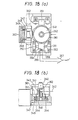
- An example of such two-dimensional actuator is shown in Figure 18. It is a mechanism which moves an objective 340 in parallel with an optical axis 342 for the purpose of focusing, and which moves it perpendicularly to the optical axis for the purpose of tracking.
- (a) of Figure 18 is a top plan view, while (b) is a side elevational view.
- the optical axis 342 is curved by a mirror 343, and agrees with the optical axis of the objective 340.
- the objective 340 is supported by a metallic spiral ring spring 341, and a frame member 361 for keeping the outer peripheral part of the spring is coupled to a supporting portion for driving the track direction.
- a coil 344 is wound on the lower part of a frame member 362 coupled to the inner peripheral part of the spring, and the objective 340 is driven in parallel with the optical axis by current which is caused to flow through the coil 344 electromagnetically by a magnetic circuit consisting of a permanent magnet 345, a center pole 346 and a yoke.
- the mirror 343 is coupled on the center pole 346.
- a coil 348 is wound on the fore end of the supporting portion 347, and the objective is driven in the radial direction of tracks by a magnetic circuit consisting of a permanent magnet 349, a center pole 350 and a yoke.
- a plain bearing 351 is coupled to the frame member 361 for keeping the ring spring 341, a shaft 352 lies in contact with the plain bearing 351, and the shaft 352 is mounted on a bed 353 for supporting it and is fixed to a base.
- the mechanism for driving the objective in parallel with the optical axis and the miror 342 are driven unitarily.
- the center of the field of view of the lens conforms with the movement of the two-dimensional actuator in the track direction, and hence, the positional deviation of the mechanism supporting the objective 340 and the mirror 342 unitarily may be known.
- a permanent magnet 354 is mounted on the plain bearing 351
- Hall elements 355 and 356 are mounted on the base to which the shaft supporting portion 353 is fixed.
- the output of this differential amplifier indicates the deviation between the geometrical center of the two Hall elements 355 and 356 and the permanent magnet 354.
- the optical axis of the objective and the positions of the tracks correspond at 1 to 1 in the tracking of the tracks by the two-dimensional actuator, and hence, the output of the differential amplifier 357 represents the deviation between the track and the geometrical center of the Hall elements 355 and 356 set in the linear motor. Accordingly, the output of the differential amplifier 357 is used as the signal F' of the positional control of the linear motor.
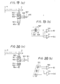
- Figure 19 is a principle diagram of a tracking signal detecting system which utilizes diffracted light, and (a) shows the simplified arrangement of an optical system.
- a light source 504 for example, a semiconductor laser
- the beam is passed through a polarizing beam splitter 502 and a quarter-wavelength plate 501, and is converged by an objective 500 onto a disc 3 which rotates about the axis of rotation 4.
- the resulting reflected light passes through the objective 500 again and has its polarization plane rotated by 90° with respect to that of the incident light by means of the quarter-wavelength plate.
- the beam has its optical path curved toward a converging lens 505 by the polarizing beam splitter 502, and is condensed toward a convergence point 506 by the converging lens 505.
- a photodetector 507 is arranged between the converging lens 505 and the convergence point 506. (b) of the figure elucidates the structure of the photodetector 507 and means for detecting the tracking signal 52 and the information signal 512.
- the photodetector 507 is constructed of bisected photodetectors 508 and 509.
- the tracking signal 52 is obtained in such a way that outputs from these photodetectors have their difference taken by a differential amplifier 510, while the infor- . mation signal 512 is obtained in such a way that the sum of the outputs of the photodetectors 508 and 509 is taken by an adder 511.
- Figure 20 is a principle diagram of a tracking signal detecting system which employs two spots.
- a diffraction grating 514 is arranged behind the coupling lens 503 so as to split the collimated beam into three.
- three spots are formed on the surface of the disc.
- One of them is arranged in the middle of the track, and the remaining two spots are arranged symmetrically in a manner to slightly shift from the middle of the track.
- the photodetector 513 is arranged on the convergence point 506 of the converging lens, three spots enclosed with a dotted line are formed thereon as shown in (b) of the figure.
- the photodetector 513 is constructed of three independent photodetectors in correspondence with the three spots. An output from the middle photodetector passes through a buffer amplifier 515 and becomes the information signal 512, while outputs from the remaining two photodetectors enter the differential amplifier 510 and generate the tracking signal 52.
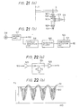
- Figure 21 is a principle diagram of a wobbling or prewobbling tracking signal detection system.
- a photodetector 516 is placed at the convergence point 506 of the converging lens 505, and an optical system similar to that of Figure 19 is constructed.
- the photodetector 516 is a photodetector having a single light receiving portion, and a single light spot (hatched area) is formed on the face of the photodetector.
- a buffer amplifier 517 When the output of the photodetector 516 is amplified by a buffer amplifier 517, it becomes the information signal 512.
- This signal is passed through an envelope detection circuit 519 so as to eliminate the influence of a recorded data signal, and it is passed through a band-pass filter 520, the center frequency of which is the frequency of wobbling or prewobbling, so as to extract the wobbling or prewobbling component. Then, it is applied to a synchronous detection circuit 521.
- the synchronous detection circuit 521 is supplied with the signal 522 of the wobbling frequency having a reference phase, and it performs synchronous detection to provide the tracking signal 52.
- the signal 522 having the reference phase is produced from the information signal 512 in case of the prewobbling, and it is produced from a signal for driving the optical head orthe deflector in the track direction, in case of the wobbling.
- the values of a capacitor C and a resistor R, which determine the time constant of the envelope detection circuit 524, are so selected that the time constant becomes sufficiently smaller than the lowest repetition frequency due to the information bit in the information signal 512 and becomes sufficiently greater than the highest repetition frequency of the total reflected-light quantity signal 51 at the passage through the guide groove.
- the tracking signal 52 means similarto the above is applicable in orderto eliminate the influence of the information bit.
- a high precision of about 0.1 pm to a target guide groove and an access time equivalent to that of the conventional magnetic disc can be achieved in the presence of the eccentricity of the guide groove, etc.
Landscapes
- Moving Of The Head For Recording And Reproducing By Optical Means (AREA)
- Optical Recording Or Reproduction (AREA)
- Laser Surgery Devices (AREA)
Description
- The present invention relates to an optical memory apparatus according to the precharacterizing part of
claim 1. - Such an optical memory apparatus is known from the GB-A-2 000 612.
- At present, an optical memory apparatus called "optical disc" has been proposed wherein a rotary disc, in which a predetermined substrate is vapor-coated with an information recording medium (e.g., a metal film), is irradiated with a laser beam which is fined into a spot of approximately 1 pm in diameter and the irradiation power of which is modulated thereby to thermally provide recesses (called "pits") in the recording medium and to record information, and wherein at playback, a weak laser beam is condensed and projected on the recording medium, and the information is read by utilizing variation in the quantity of reflected light from the pits. Such proposal has been made in 'Electronics', Nov. 23, 1978, p. 75, "Ten Billion Bits Fit onto Two Sides of 12-inch disc". A typical example of arrangement of the memory apparatus is shown in Figure 1.
- Here, a disc (partly broken away in the illustration of the figure) 3 having a diameter of approximately 30 cm is rotated in the direction of an arrow about a
rotary shaft 4 by a drivingmotor 5. Anoptical head 2, which is constructed of a laser source and an optical system, is carried on aswing arm actuator 1 having been used in a magnetic disc etc. and is driven in the radial direction of thedisc 3. - The
disc 3 has its surface covered with a transparentprotective film 6 of glass of the like. In the figure, theprotective film 6 is further partly broken away, to illustratepits 12 to be stated later. - Methods of recording and playing back information in such arrangement will be described with reference to Figure 2 in which the illustrated part A of the
disc 3 is shown on an enlarged scale. - On a
substrate 11 of glass or plastics, guide grooves (called "tracks") 13 of a concave sectional structure having a certain degree of width and depth are formed by the use of an ultraviolet- settingresin 14 orthe like. Further, ametal film 10 is evaporated on theresin 14, whereupon theprotective film 6 is deposited. In case of recording, the focused spot of light from theoptical head 2 is guided along theguide grooves 13, that is, the light spot tracks theguide grooves 13, and themetal film 10 is dissolved by the light spot so as to form thepits 12. In case of playback, a light spot is similarly projected along theguide grooves 13, and the quantity of the resulting reflected light is read. - Further, signals for controlling the light spot are detected from the quantity of the reflected light. The signals for controlling the light spot are, in the main, the two of a focal deviation detecting signal for detecting a focal deviation ascribable to the vertical oscillations of the disc, and a tracking deviation detecting signal for detecting the deviation between the center of the light spot and the center line of the guide groove. All such signals use the quantity of the reflected light from the metal film, namely, the area other than the pits.
- Assuming the pitches of the guide grooves to be 1.6 pm, one side of the disc having a diameter of 300 mm is provided with about 50,000 guide grooves, and data to be received per guide groove become about 4,000 bytes.
- In each guide groove, a plurality of sectors for indicating the limits of the data are provided in the rotational direction of the disc in advance. In recording an external information at any desired position or playing back the recorded information, the access operation of looking for one guide groove out of the surface of the disc and finding out one sector on this guide groove is required. That is, there are required the so-called "seek" operation of moving the light spot to a selected guide groove where desired information is recorded or it is to be recorded, and the so-called tracking of maintaining the light spot on the center line of the guide groove with the minimum deviation throughout the period of time during which the information is being read or being recorded.
- As an apparatus requiring such access operation, there has heretofore been known the magnetic disc. Since, however, the track pitches of the magnetic disc are about 150 pm to 30 pm and are one order to two orders of magnitude greater than the pitches of the guide grooves of the optical disc, positioning based on the same access operation as in the magnetic disc cannot be applied to the optical disc. More specifically, when a magnetic head is brought to a desired track by an actuator (for example, a voice coil type linear motor), a steady state error (an offset from the target position) of about 5-10 pm develops though it differs depending upon the construction and performance of the actuator. It is caused by friction etc. Moreover, in the transient state of the positional control, an overshoot can take place with respect to the target position, and it amounts to about 5 pm. In this manner, with the access means employed in the magnetic disc, the stop precision is as very low as about 10 pm. Since, as described before, the pitches of the guide grooves of the optical disc are about 1.6 pm at the least for the time being, the positioning of the optical disc is difficult with the access method of the magnetic disc.
- Besides, in cases where the actuator undergoes the maximum acceleration and the maximum deceleration, it is feared that the actuator itself will vibrate in the order of Ilm. This leads to the problem that information from the disc cannot be read out during the seek control.
- Furthermore, unlike the magnetic disc, the optical disc does not include a disc and a servo head for positioning. This leads to the problem that the exact position of the optical head cannot be detected.
- The optical memory apparatus known from the GB-A-2 000 612 is concerned with a read only system (only play back operation). Thereby it is always assumed that there are recorded data (informations bits) and therefore there cannot be a coexistence of non-recorded guide grooves and recorded guide grooves. In the known optical memory apparatus in order to detect an envelope signal the reproduction signal obtained from the recording medium is passed through a high-pass filter and the output signal of this high-pass filter is then detected by an envelope detector.
- An object of the present invention is to solve the problems described above, and to provide an optical memory apparatus being adapted for recording and playing back information and having an access device for positioning a light beam to a desired guide groove on the recording medium.
- According to the invention this object is solved by a memory device of the kind referred to in the precharacterizing part of
patent claim 1 comprising the features disclosed in the characterizing part ofpatent claim 1. Theclaims 2 to 10 characterize advantageous developments thereof. - In order to achieve high-precision positioning, first of all, the exact position of an optical head under an access operation must be detected. To this end, it is considered to use a tracking deviation signal (tracking signal) at the time at which a light spot passes through a guide groove (track). However, in case of executing the seek control and the follow-up control by the use of this signal, the following disadvantage is solved. At the start and end of the seek control, the moving speed of the optical head becomes very low. When this speed has become lower than the eccentric maximum speed caused by the eccentricity of tracks, a miscount occurs in case of counting the number of tracks each time one track is passed, so that an exact position cannot be detected.
- More specifically, referring to Figure 3, the
trace 40 of the light spot corresponds to a case where the light spot has passed through a group of eccentric tracks at the maximum speed of eccentricity. Individual solid lines represent the variations-with-time of the positions of the tracks in the radial direction of the disc. In this case, the count value of the passage through the tracks and the number of tracks having been passed are in agreement. In contrast, thetrace 41 of the light spot corresponds to a case where the light spot has passed through the group of tracks at a speed lower than the maximum speed of the eccentricity. In this case, the count value of the passage through the tracks does not agree with the number of tracks having been actually passed, but the former is larger. - In the present invention, therefore, the direction in which the light spot passes through the guide groove (track) and the number of the guide grooves which have been passed are detected by the use of a signal indicating the total quantity of reflected light at the passage of the light spot through the guide groove and the tracking deviation signal (tracking signal), and the addition or subtraction of the guide grooves passed is executed in accordance with the direction of the passage, thereby to detect the exact position of the optical head, that is, the light spot.
- Further, the present invention comprises a first actuator which has a movable range extending over a full radius of the disc, and a second actuator which has a minute variable range and which exhibits a high responsibility. Thus, a positioning precision unattainable with only one actuator is realized by interlocking the two actuators. At this time, a method of controlling the two actuators becomes a problem. In the present invention, the problem is solved in such a way that the movement of the second actuator for high-precision positioning is detected, and that the first actuator for approximate positioning over the full radius of the disc is driven in interlocking with the detected movement.
-
- Figure 1 is a schematic arrangement view of an optical memory apparatus;
- Figure 2 is a partially enlarged sectional view of a disc;
- Figure 3 is a diagram for explaining the relationships between light spot traces and eccentricity;
- Figures 4(a), 4(b) and 4(c) are diagrams for explaining methods of detecting signals at the time of passage through a track;
- Figure 5 is a waveform diagram for explaining a position detecting method;
- Figure 6 is a circuit block diagram for explaining positional detection;
- Figure 7 is a circuit block diagram for explaining speed detection;
- Figure 8 is a waveform diagram for explaining the timings of the positional control;
- Figures 9 and 10 are circuit block diagrams for explaining the positional control;
- Figure 11 is a block diagram showing an embodiment of the present invention;
- Figure 12 is a block diagram showing another embodiment of the present invention;
- Figures 13 and 14 are diagrams for explaining the operation of the embodiment in Figure 12;
- Figure 15 is an arrangement diagram of a simulator circuit for use in the embodiment of Figure 12;
- Figure 16 is a diagram for explaining a mirror deflection detecting method for use in the present invention;
- Figure 17 is a block diagram showing still another embodiment of the present invention;
- Figures 18(a) and 18(b) are views showing the construction of a two-dimensional actuator; and
- Figures 19(a) and 19(b), Figures 20(a) and 20(b), Figures 21(a) and 21(b) and Figures 22(a) and 22(b) are diagrams for explaining methods of detecting a tracking error signal and a total reflected-light quantity signal for use in the present invention.
- First, there will be described a method of exactly detecting the position of an optical head from a signal indicating the total quantity of reflected light and a tracking signal. Figures 4(a), 4(b) and 4(c) are explanatory diagrams of methods of producing signals expressive of the direction in which the optical head passes through a track, and the passage through the track, in order to exactly detect the position of the optical head from a disc. Referring to Figure 4(a), light rays emergent from the light source of the optical head are condensed by an objective (not shown), to form a
spot 50 on ametal film 10 through asubstrate 11 of the disc and aUV resin 14 forming guide grooves (tracks) 13. At this time, assuming that the N.A. (numerical aperture) of the objective is 0.50 and the wavelength of the light source is 830 nm, a spot size (a diameter at which an intensity of 1/e2 is established) becomes about 1.6 pm. It is assumed that the pitches of the guide grooves made on the disc are 1.6 pm. Then, as the spot moves radially of the disc in the direction of an arrow, atracking signal 52 expressing the deviation between the center line of the guide groove and the center of the spot varies as shown in Figure 4(b). Regarding the production of this signal, there are a method employing two spots as disclosed in Japanese Laid-open Patent Application No. 49-50954, a method of spot wobble as disclosed in Japanese Laid-open Patent Application No. 49-94304, a method of track wobble as disclosed in Japanese Laid-open Patent Application No. 50-68413, a method employing diffracted light as disclosed in Japanese Laid-open Patent Application No. 49-60702, etc. In addition, when the spot moves in the direction of the arrow, the total quantity of reflected tight from the disc varies as shown in Figure 4(c). The total quantity of reflected light becomes the smallest at the center line of the guide groove, and becomes the largest at the middle line between the adjacent guide grooves. Asignal 51, which is obtained by detecting the total quantity of reflected light and converting it into an electric signal by means of a photodetector, so relates to thetracking signal 52 as to be equal in period and shift by 90° in phase. Thetracking signal 52 becomes null at the center line of the guide groove, and its sign differs depending upon whether the light spot lies on the right side or the left side of the guide groove (corresponding to the outer peripheral side or the inner peripheral side of the disc). By utilizing this feature, the direction in which the guide groove is passed can be known. - The "total quantity of reflected light" mentioned here denotes the total quantity of light which has passed and arrived through the apertures of a lens having a certain specified numerical aperture, when the reflected light from the disc has been condensed by the lens. This sort of light quantity is used for detecting an information signal recorded on the disc. The information signal is obtained in such a way that a light beam arriving through the lens aperture is condensed on the light receiving face of a single photodetector and is converted into a photocurrent, that the light beam is projected on a group of photodetectors having a plurality of light receiving faces, photocurrents from the respective photodetectors being summed, or that the photocurrents are converted into voltages, which are added up. The resulting signal can be used as the
aforementioned signal 51 of the total quantity of reflected light. - There will now be stated a method of executing exact positional detection by the use of the
tracking signal 52 and the total reflected-light quantity signal 51. - (a) in Figure 5 shows the A.C. component of the total reflected-light quantity signal. (b) in the figure shows the tracking signal. In this embodiment, letting plus (+) denote a situation where the spot lies on the inner side of the disc and minus (-) denote a situation where it lies on the outer side of the disc, the variations of the two signals versus a time axis are illustrated as to a case where the light spot has moved from the outer side toward the inner side of the disc, has stopped halfway and has moved in the opposite direction. (c) in Figure 5 shows a
track signal 90 indicating places in which guide grooves exist. This signal exploits the fact that the total quantity of reflected light decreases in the place where the guide groove exists. The signal of the total quantity of reflected light is compared with a certain voltage Ei, and a case where the former is smaller than the latter is caused to correspond to the state of logic level "0". Then, when the variation of thesignal 90 is observed on the time axis, the fall of the waveform corresponds substantially to that edge of the guide groove at which the spot begins to traverse this guide groove. Therefore,pulses 92 of small time width ((e) in Figure 5) are prepared from the falls. On the other hand, in order to know the direction in which the spot passes through the guide groove, a signal (called "track sign signal") 91 ((d) in Figure 5) is prepared by comparing thetracking signal 52 with the zero level. The direction of the passage through the guide groove can be known by comparing thetrack sign signal 91 with the timing of the trackpassage edge signal 92. Accordingly, when it is desired to know the number of the guide grooves through which the light spot has passed when moving from the outer side toward the inner side, the number of pulses of a track passage edge signal 53 ((g) in Figure 5) at the time at which thetracking signal 52 becomes minus, that is, at which thetrack sign signal 91 becomes a low level, may be counted. The same applies to the movement in the opposite direction. An example of a practicable circuit for realizing the operations described above is shown in Figure 6. The total reflected-light quantity signal 51 is applied to the (+) terminal of a comparator 92a, and the voltage E, is applied to the (-) terminal thereof, thereby to make the comparison between the total reflected-light quantity signal 51 and the voltage El. An output logic level becomes "1" when the level of thesignal 51 is greater than E1, and it becomes "0" in the other case. Theoutput signal 90 is applied to amonostable multivibrator 94 so as to form the pulses of fixed width from the falls of thesignal 90. Thisoutput signal 92 is applied to one terminal of each of ANDcircuits circuits sign signal 91 obtained by applying thetracking signal 52 to acomparator 93b, and a signal obtained by inverting thesign signal 91 by means of aninverter circuit 96. The respective ANDcircuits direction edge signal 53 which generates the pulse each time the light spot passes through the track from the outer side to the inner side. Thus, using these signals, it is possible to know the number of remaining tracks up to a target track being accessed, which number is required for a speed control. In the circuit of Figure 6, anaccess sign signal 56 indicating the direction of the access is caused to correspond to, for example, the logic level "0" in case of accessing the target track from the outer side toward the inner side. Then, a logic circuit consisting oflogic elements direction edge signal 54 and applies it to the Up terminal of acounter 104, and it selects the minusdirection edge signal 53 and applies it to the Down terminal of thecounter 104. At the start of the access, thecounter 104 is loaded with theabsolute value 55 of a difference up to the target guide groove located on the inner side. When the light spot has started moving from the outer side toward the inner side, the pulse appears in the minusdirection edge signal 53 and decreases the content of thecounter 104 each time the light spot traverses one guide groove from the outer side toward the inner side. On the other hand, when the light spot comes back halfway for any reason and traverses one guide groove from the inner side toward the outer side, the pulse appears in the plusdirection edge signal 54 and increases the content of thecounter 104. Thus, thecounter 104 delivers the exactabsolute value 57 of the remaining guide grooves in the access operation. When the content of thecounter 104 has become zero, a pulse A which indicates this fact is provided from the BR terminal of thecounter 104. From this pulse A, it can be known that the light spot has reached the edge of the target guide groove. - Using the plus and minus direction edge signals 54 and 53, the absolute value of a speed in the access operation, the value being required for the speed control, can be known. By way of example, in a circuit of Figure 7, the minus
direction edge signal 53 is applied to a frequency-to-voltage converter 105, while the plusdirection edge signal 54 is applied to a frequency-to-voltage converter 106. Letting p denote the pitch of the guide grooves and v denote the absolute value of the speed of the passage through the guide groove, the frequency f of a train of pulses each of which appears at the edge of the guide groove at the passage through this guide groove is given by the following expression: -

- By knowing this frequency, accordingly, the absolute value of the speed at which the light spot passes through the guide groove can be known. The direction of the passage can be known from the existence of the pulse of the
edge signal V converters differential amplifier 107, the output of which is applied to both the input of aninverter circuit 108 and aswitching circuit 109. The output of theinverter circuit 108 is applied to aswitching circuit 110, which is controlled by the inverted signal of thecontrol 56 for controlling theswitching circuit 109. The outputs of the switchingcircuits signal 111 expressive of the absolute value of the speed. More specifically, as regards theaccess sign signal 56, the access from the inner side toward the outer side is now caused to correspond to logic level "1". In case of the access from the inner side to the outer side, therefore, the FN conversion output of the plusdirection edge signal 54 brings the differential output into the + sign. Then, since the access sign signal is "1", theswitching circuit 109 turns ON, and this appears as theabsolute value signal 111 of the speed. Conversely, in case of access from the outer side to the inner side, theaccess sign signal 56 is "0" in terms of the logic level. Therefore, theswitching circuit 110 is turned ON by the output of aninverter 112 for inverting theaccess sign signal 56. Besides, the FN conversion output of the minusdirection edge signal 53 brings the output of thedifferential amplifier 107 into the - sign, but the latter is rendered the ± sign by theinverter circuit 108. This appears as theabsolute value signal 111 of the speed. - Now the procedure of preparing a timing signal for changing-over the speed control to the positional control will be described with reference to Figure 8. The servo system of the positional control is usually designed on the assumption of the performance of a linear operation. This comes from an easy analysis and a simple circuit arrangement. As shown in Figure 4(b), however, the
tracking error signal 52 varies sinusoidally as a function of the track position and exhibits a nonlinear characteristic as a control input. In such system, the timing at which the operation of the servo system is started becomes an important factor for the stable operation of the system. Referring to (a) of Figure 8, when the spot has traversed the disc from the inner side to the outer side thereof, to come close to the N-th target guide groove, thetracking error signal 52 varies as illustrated. When the tracking error signal is expressed as a sinusoidal wave whose origin is a target point 115 (the zero point of the tracking error signal), the timing (of the start of the positional control) for executing the stable operation extends, according to experiments, between the peak points of the + and - signs closest to the target point (within ±rr/2 in terms of the phase of the sinusoidal wave). More suitable is a linear region whose point of symmetry is the origin. In addition, the servo system needs to be operated at an edge part before the passage through the zero point of the target guide groove. With the above taken into consideration, when the spot approaches the target guide groove from the inner side toward the outer side of the disc, the positional servo system may be turned ON after the spot has passed through the zero point of a guide groove directly preceding to the target guide groove and has passed through the next plus peak point. Conversely, when the spot approaches the target guide groove from the outer side toward the inner side of the disc, the positional servo system is turned ON after the spot has passed through the zero point of the guide groove directly preceding to the target guide groove and has passed through the next minus peak point. Circuits for realizing the above are shown in Figures 9 and 10. (a), (b), (c) and (g) in Figure 8 show thetracking error signal 52 at the time at which the spot has approached the target guide groove from the inner side toward the outer side of the disc, asignal 113 indicating linear regions, a signal B indicating the turn-ON of the positional servo system, and a signal 144 indicating the arrival at the target guide groove, respectively. Referring to Figure 9, thetracking error signal 52 is applied to the + terminal of acomparator 117, the - terminal of which is supplied with a voltage E2. As indicated in (a) of Figure 8, the level of the voltage E2 is set at a positive level which is substantially linear to thetarget point 115 of thetracking error signal 52. The output of thecomparator 117 is applied to one input terminal of an ANDcircuit 120, the other input terminal of which is supplied with theaccess polarity signal 56. Thetracking error signal 52 is also applied to the - terminal of acomparator 118, the + terminal of which is supplied with a voltage E3. As indicated in (a) of Figure 8, the level of the voltage E3 is set at a negative level which is substantially linear to thetarget point 115 of the tracking error signal 152. The output of thecomparator 118 is applied to one input of an ANDcircuit 121, the other input of which is supplied with a signal obtained by inverting theaccess sign signal 56 by means of aninverter 119. The outputs of the ANDcircuits circuit 122 which takes the logical sum thereof. Thus, theoutput 113 of theOR circuit 122 becomes the waveform as shown in (b) of Figure 8, when theaccess sign signal 56 is "1", and it becomes a waveform as shown in (e) of Figure 8, when theaccess sign signal 56 is "0". In both cases, the fall of a pulsative signal represents the end of the linear region whose center is the target point. In order to perform the positional control of the light spot to thetarget point 115 of the target guide groove, the linear region of the target guide groove needs to be known. Therefore, the BR output (the signal provided when thecounter content 57 has become zero) A of thecounter 104, which has been explained with reference to Figure 6, is used. As explained with reference to (f) and (g) of Figure 5, thepulses counter 104 has become zero, it is applied to a flip-flop 128 so as to prepare thesignal 114 which rises at the rise of the signal A. Thesignal 114 is applied to one input of an ANDcircuit 123, and thesignal 113 is applied to the other input thereof, whereby the linear region of the target guide groove is selected by thesignal 114. The output of the ANDcircuit 123 is applied to a trailing edge reaction type (master- slave type) flip-flop 124, to generate a positional control start signal B which rises at the trailing edge of the applied input. The signal B can also be formed by the circuit shown in Figure 10. Thetracking error signal 52 is applied to aswitching circuit 125, while it is applied to and inverted by an invertingamplifier 116, the inverted signal entering aswitching circuit 126. Theswitching circuit 125 is controlled by theaccess sign signal 56, and theswitching circuit 126 is controlled by a signal obtained by inverting theaccess sign signal 56 by means of aninverter 119. The outputs of the switchingcircuits comparator 127. The voltage E2 is applied to the - terminal of thecomparator 127. Thus, thesignal 113 in which the fall of the comparator output represents the end of the linear region having the target point as its center is generated. The subsequent processing is the same as the operations in Figure 9. In this case, the positive peak level and the negative peak level of thetracking error signal 52 must be substantially equal. The circuit of Figure 10 corresponds to a case of processing the first half portion of the circuit of Figure 9 analogously. A general system for performing the access operation by adopting the present invention thus far stated, will be described with reference to Figure 11. In the present embodiment, the seek control and the follow-up control are carried out by a single actuator, and an optical head to be placed on the actuator is made light in weight and small in size. Regarding the construction, by way of example, the optical head can be placed on the arm portion of the swing arm explained with reference to Figure 1. - The quantity of reflected light detected by the
optical head 2 is subjected to photoelectric conversion by a photodetector (not shown), and the resulting electric signal is applied to a tracking errorsignal generator circuit 201 and a total reflected-light quantitysignal generator circuit 200. Here, the method of preparing the tracking error signal will not be described in detail. Thetracking error signal 52 is obtained from the tracking errorsignal generator circuit 201, while the total reflected-light quantity signal 51 is obtained from the total reflected-light quantitysignal generator circuit 200. Thetracking error signal 52 and the total reflected-light quantity signal 51 are applied to an edgesignal generator circuit 202, which generates the plusdirection edge signal 54 and the minusdirection edge signal 53, and they are operated and processed therein. The arrangement of the edgesignal generator circuit 202 has been described in detail in conjunction with Figure 6. The plus and minus direction edge signals 54 and 53 are applied to both adifferential counter 203 for calculating the difference up to the target guide groove and avelocity detecting circuit 204, which deliver theabsolute value signal 57 of the difference up to the target guide groove and theabsolute value signal 111 of the velocity respectively. Regarding these, the arrangement and operations of thedifferential counter 203 have been described in detail with reference to Figure 6, while the arrangement and operations of thevelocity detecting circuit 204 have been described in detail with reference to Figure 7. Theabsolute value signal 57 of the difference up to the target guide groove is applied to a target velocitycurve generator circuit 205. The target velocitycurve generator circuit 205 delivers the optimum velocity in accordance with the difference up to the target guide groove. Ordinarily, the optimum velocity is recommended to be proportional to the square root of the difference. Here, since the output of thecounter 104 is given in digital form, a table of square roots is stored in a ROM beforehand, and atarget velocity signal 206 is delivered digitally in accordance with theabsolute value signal 57 of the difference up to the target guide groove. Thetarget velocity signal 206 is applied to a D/A (digital-to-analog)converter 207 and is converted into an analog quantity, which is applied to one input of adifferential amplifier 308. The other input thereof receives theabsolute value signal 111 of the velocity from thevelocity detecting circuit 204, so that the difference is taken. The output of the difference is applied to asign inversion circuit 209. Since the output of the difference of the velocity is an absolute value, thesign inversion circuit 209 performs the operation of affording a sign to the velocity difference in correspondence with the logic level of theaccess sign signal 56. Accordingly, the output of this circuit becomes the difference between the target velocity and the actual velocity and having the sign. This difference enters a seek control/positionalcontrol switching circuit 210, which is controlled by the timing signal B for the start of the positional control. More specifically, when the timing signal B is LOW, the seek control is established, and the signal of the velocity difference appears at the output of theswitching circuit 210 and drives theswing arm 1 through a swingarm driver circuit 251. When the seek control has ended with the light spot arriving at the target guide groove, the timing signal B becomes HIGH to switch the control to the positional control. Regarding the flow of signals for the positional control, thetracking error signal 52 is applied to a switching circuit 21.1, which is coupled to aphase compensator circuit 212 under the control of the timing signal B or when this timing signal is "high". The output of the phase compensator circuit is applied to anadder circuit 213 along with a jump signal D to be described later, and the applied signals are added therein, the sum being applied to theswitching circuit 210. In this manner, the positional control is started by the timing signal B, and the light spot can be stably introduced to the target guide groove. - The
tracking error signal 52 is also applied to a timingsignal generator circuit 214 for producing the timing signal B, along with theaccess sign signal 56 and the signal A. The arrangement and operations of thecircuit 214 have been described in detail with reference to Figures 9 and 10. - The target guide groove is tracked by the above operations, and address information stored in the guide groove is read out. Reading means therefor is omitted in the present embodiment. The read-out information is transmitted to a controller (not shown), to decide whether or not the particular guide groove is the target guide groove.
- The controller mentioned here is a control unit which controls the whole optical disc apparatus. Usually, it gives instructions or command to the driving unit (having been described in detail in the present invention) which includes the driving mechanism and the driving circuitry required, at the least, for reading and writing data, and it controls the driving unit in order to read or write data. As the function of this sort, the address of a desired guide groove from a computer connected with the controller is received in an access operation, it is compared with the address of a guide groove read out currently, the absolute value and sign of the difference of the current guide groove up to the desired guide groove are calculated, and the result is transmitted to the driving unit. The driving unit executes the seek control and the positional control by itself, and begins to read data from the target guide groove or a guide groove close thereto. Then, the controller decodes the data to know the address of the guide groove currently read out and to judge the subsequent access procedure. By way of example, when the read-out guide groove is the target guide groove, the controller transmits as a
jump number signal 58, a signal indicative of one guide groove, and a jump sign signal indicative of the direction of jump from the outer side to the inner side of the disc, on the assumption that guide grooves on the disc are recorded spirally from the inner side to the outer side. Thejump number signal 58 is applied to ajump counter 215. Thejump counter 215 transmits the sign signal of the jump to ajump signal generator 216, and generates pulses for starting the jump by the number of guide grooves to be jumped, at specified time intervals. Upon receiving the pulses, thejump signal generator 216 produces the driving signal D for executing the jump in accordance with the jump sign signal. The details of the jump operation are contained in 'Philips Technical Review', Vol. 33, p. 178, and are omitted here. - Accordingly, in order to steadily read out the target guide groove upon reaching it, the
jump number signal 58 is transmitted from the controller in the manner including the signal indicative of one guide groove to be jumped and the jump sign signal indicative of the direction of the jump from the outer side to the inner side, each time the disc executes one revolution. In a case where, when the address content recorded in the guide groove to which the light spot has been positionally controlled at the end of the access is read out, this guide groove differs from the target guide groove, the light spot is moved to the target guide groove by performing the jump, subject to the condition that the difference between the guide groove current read out and the target guide groove is smaller than a certain set number (for example, 64 or 128). At this time, the controller transmits thejump number signal 58 which contains the number of guide grooves up to the target guide groove and the direction of the jump. If the difference between the current guide groove and the target guide groove is greater than the certain set value, an access operation including the speed control will be started. This operation is the repetition of the access procedure thus far explained. - As described above, according to the present embodiment, whether the light spot passes through the guide groove on the disc from the outer side to the inner side or from the inner side to the outer side is known from the total reflected-light quantity signal and the tracking error signal, which are generated when the light spot passes through the guide groove. Thus, the position of the optical head can be exactly detected without errors attributed to an eccentricity, mechanical vibrations, etc. The aforementioned signals at the passage of the light spot through the guide groove are also utilized for the velocity detection, whereby the relative velocity between the light spot and the guide groove can be exactly detected. Further, according to the present embodiment, even when the swing arm is used as the actuator, the positioning operation is possible from the rough positioning over the full radius of the disc to the fine positioning of about 0.1 pm.
- In the next place, another embodiment of the present invention will be described with reference to Figure 12. In the foregoing embodiment of Figure 11, both the rough positioning over the full radius of the disc and the fine positioning are executed by the single actuator. With the actuator of the specified type, however, the frequency characteristic of the displacement versus the driving current becomes problematic, and the cutoff frequency cannot be made high when the servo system for the positional control is constructed. It is accordingly desirable to dispose separately from a first actuator for rough positioning, a second actuator which can move in only a minute range, but has a good frequency responsibility enough to make the cutoff frequency high even when the servo system is constructed. In this case, how the two actuators are interlocked during an access operation becomes a problem. It is the present embodiment that affords an expedient for solving the problem.
- Here, a
linear motor 314 will be exemplified as the first actuator for the rough positioning. The purport of the present invention applies also to other actuators. On the other hand, a galvano-mirror 308 or a pivot mirror is employed as the second actuator of high responsibility for the follow-up control within the minute range. Thedisc 3 is rotating in a predetermined direction about therotary shaft 4. An optical head 2' is placed on amovable bed 315, which moves on a base 309 asrollers 310 rotate. Themovable bed 315 is coupled to acoil 311 through a supportingmechanism 313, and it is driven by the electromagnetic forces of amagnet 312 and current flowing through thecoil 311. The optical head 2' includes therein an objective 306 which serves to form the light spot on the disc, the galvano-mirror 308 which is means for deflecting the light spot on the surface of the disc, aphotodetector 307 which receives reflected light from the disc surface, a light source, an optical system which leads a light beam from the light source to the objective, and an optical system which leads the reflected light to the photodetector. Since the light source and the optical systems are necessary for explaining the present invention, they are not illustrated. - The process in which the total reflected-
light quantity signal 51 and thetracking signal 52 are produced from the output of thephotodetector 307, whereupon thesignals block 214 for producing the timing signal B of the positional control from thetracking error signal 52, and the portion for effecting the jump function are not explained, either, because they are the same. Only the procedure of the positional control will be explained. Theswitching circuit 211 is turned "on" by the timing signal B of the positional control, and it leads thetracking error signal 52 to thephase compensator 212 so as to subject the signal to the phase compensation of enhancing the stability and follow-up performance of the control system. After the compensated signal has been added to the jump signal D by theadder circuit 213, it becomes a mirror driving signal E. The mirror driving signal E drives the galvano-mirror 308 through a galvano-mirror driver circuit 305, so as to cause the light spot to track a guide groove. In this state, there is not a target signal for a position to which the first actuator is positioned, and hence, the positioning signal needs to be prepared. - Here, the positioning signal will be described. When the linear motor moves radially on the disc surface under the condition that the light spot is fixed at the center of the field of view of the objective to be stated later, the
tracking error signal 52 varies versus the magnitude of the movement as illustrated in Figure 13. It is also considered to use thistracking signal 52 as the positioning signal for the linear motor. Since, however, the linear range A of this signal is only to the extent of the width of the guide groove, the control will be impossible unless the follow-upprecision 6 falls within this range. With conventional linear motors, the follow-up precision amounts to 2-3 um and even to about 10 pm when it is great. However, the pitch p of guide grooves in the optical disc is about 1.6 pm to the end of recording information at high density, and the width A of the guide groove becomes about 0.8-0.6 pm. It is accordingly impossible to perform the positioning control of the linear motor by using thetracking error signal 52 and with thecenter line 405 of the guide groove as a target. It is therefore necessary to prepare a signal which expresses the deviation between the target guide groove being tracked and the linear motor and whose linear region is wider than the linear region of the tracking error signal, and to perform the positioning of the linear motor by the use of this signal. As such signal, there is the trace of the light spot followed up by the galvano-mirror. More specifically, each circular region indicated by a dotted line in Figure 14 is the field ofview 402 of the objective, and atrace 403 is the trace versus the time t, of the guide groove being tracked by the galvano-mirror. The guide groove being followed up within thelens view field 402 varies sinusoidally versus the time due to an eccentricity, as illustrated in the figure. Since the objective is fixed to the movable bed of the linear motor, thecenter 404 of thelens view field 402 moves unitarily with the linear motor. The neutral point of the galvano-mirror (determined when the mirror has been mechanically set on the movable bed of the linear motor) is uniquely determined owing to the spring supporting mechanism when the driving signal E is null. Usually, adjustments are so made that when the galvano-mirror lies at the neutral point, the light spot is situated at thecenter 404 of theobjective view field 402. The reason for such adjustments is that the residual aberration of the lens is the least at the center of the lens view field. Between the movement value of the light spot within the lens view field and the angle of rotation of the galvano-mirror, there is a certain linear relationship which is determined by an optical arrangement relation and the focal distance of the objective. Accordingly, the deviation from the center of the lens view field to the guide groove being tracked by the light spot can be known from the rotational angle of the galvano-mirror. - The rotational angle of the galvano-mirror can be known from the driving signal E. Although the rotational angle of the galvano-mirror has a characteristic differing in dependence upon the frequency components of the driving signal E (that is, a frequency response), the characteristic is already known. Even when, under the state under which the center of the lens view field is held in agreement with the
center line 405 of the guide groove in Figure 13 and under which the the linear motor is stopped, the galvano-mirror is driven and the light spot is moved from one end to the other end of the view field of the objective, thetracking error signal 52 is detected similarly to the foregoing. The galvano-mirror driving signal E at this time becomes null at thecenter line 405 of the target groove, and it has the minus sign at one end of the lens view field and the plus sign at the other end. It falls into a linear relation to the light spot within the lens view field, and its linear region extends over the whole view field of the objective. - In the arrangement of Figure 12, the driving signal E is applied to a
circuit 300 for simulating the frequency characteristic of the galvano-mirror, to form a signal F of the deviation of the light spot from the center of the lens view field. The signal F is passed through aphase compensator 301 via aswitching circuit 316, which is turned "on" by the timing signal B of the positional control, so as to drive the linear motor. In this manner, the position of the linear motor is controlled so that the light spot may come to the center of the lens view field. Herein, the deviation signal F of the light spot from the center of the lens view field has a wide linear region, which is at least 100 pm or so. Therefore, the signal has no problem even when the follow-up precision of the linear motor amounts to 2-3 pm. - In Figure 14, each
circular region 406 of solid line is the field of view of the objective after the above operations have been performed. - More specifically, since the light spot tracks the
guide groove trace 403, the positioning of the linear motor is performed upon detecting the deviation between the light spot and thecenter 407 of the lens view field. Therefore, the center of the lens view field (indicated by each white circle) 407 unitary with the linear motor follows up the light spot, but it deviates by the component of the aforementioned position error 6 (explained as the follow-up precision). While the positioning error differs depending upon the characteristics of the positioning servo system of the linear motor, Figure 14 illustrates a case of a system which has a servo band capable of following up a large eccentric component. Enhancing the band of the linear motor positioning servo system in the present invention has another effect. That is, since the linear motor is controlled so that the light spot may always come to the vicinity of the center of the view field of the objective, a region of little residual aberration becomes usable. As a result, the spot size (the diameter at which the light intensity distribution becomes 1/e2 of the maximum value) of the light spot becomes the smallest. Thus, in a playback operation, the amplitude of a playback signal from a recorded pit becomes large, while in a recording operation, the emission power of a light source required for forming a pit of prescribed diameter may be low. Conversely, when the spot size required for the optical disc apparatus is determined at a certain value, the aberration may be reduced at only the center of the field of view, and hence, the objective becomes smaller in the number of constituent lenses and becomes lighter in weight, smaller in size and lower in cost, as compared with that in the method in which the spot is moved within the objective view field by the use of the galvano-mirror. - A practicable example of the
circuit 300, by which the deviation signal F of the light spot from the center of the lens view field is produced from the driving signal E, is shown in Figure 15. The driving signal E enters abuffer amplifier 302, and is delivered to an electric circuit having a characteristic similar to the frequency characteristic of the galvano-mirror. Since the driving voltage (or current) -versus- deflection angle characteristic of a conventional galvano-mirror exhibits the characteristic of a second-order low-pass filter, this embodiment uses a second-order low-pass active filter which consists of capacitors Ci, C2, resistors Ri, R2 and abuffer amplifier 304. The output of this filter accordingly represents the deflection of the galvano-mirror. The deflection of the galvano-mirror and the movement of the spot on the lens view field are usually in a linear relationship. Therefore, the deviation signal F of the light spot from the lens view field is obtained by compensating the sensitivity (as to the deflection angle and the spot movement value) through alinear amplifier 303. - As the method of detecting the deviation signal of the light spot from the lens view field, there is a method of detecting the deflection angle of the mirror directly, otherwise than the electrical simulation from the mirror driving signal E. Figure 16 shows a practicable example of such method. A
light beam 328 emergent from a light source (not shown) enters amirror 320 along anoptical axis 329, and it is reflected in the direction of 45° so as to have its optical path curved toward an objective (not shown). Apermanent magnet 321 is mounted on the rear surface of themirror 320, and an electromagnetic force is generated by current flowing through acoil 322 surrounding the magnet, so that the mirror is rotated about abearing 331. Thebearing 331 is fixed to apart 332 of the optical head by a supportingrod 330. Thebearing 331 is formed of a rubber material which is flexible. This structure is a kind of pivot mirror. In order to detect the deflection angle, a light beam from alight emitting diode 326 is condensed on the reflective surface of themirror 320 by alens 327, and the resulting reflected light beam is received by twophotodetectors optical axis 329 of the light beam reflected by themirror 320 is aligned so as to agree with the optical axis of the objective in the state in which the driving voltage is null. Thereafter, the light beam from the light emitting diode is adjusted so as to be equally received by thephotodetectors photodetectors differential amplifier 325 to take the difference of them, the output F' becomes a signal expressive of the deflection angle of the mirror. The method of directly detecting the deflection angle of the mirror in this manner makes it possible to know the movement of the mirror due to a mechanical oscillation. It is therefore effective in a case where the mirror placed on the linear motor might oscillate when the linear motor performs the acceleration or attenuation of the maximum number G in the rough positioning. That is, the movement of the mirror is detected, the mirror is positioned to the first set point, and the optical axis of the objective can be prevented from fluctuating. Accordingly, the signal F' can be used for the foregoing operation when the rough positioning is being executed by the velocity control of the linear motor, and it can be used as the deviation signal from the center of the lens view field when themirror 320 is deflected so as to minutely position the light spot. An embodiment in which the above signal F' obtained by directly detecting the mirror deflection angle is used for access, is shown in Figure 17. The velocity control employing the linear motor is the same as in the embodiment thus far described, and portions represented by the same block Nos. are common and will not be explained repeatedly. Since the timing signal B of the positional control is "low" in the velocity control, aswitching circuit 333 allows the mirror deflection signal F' to pass therethrough during this period only, and it controls so as to prevent thedeflection mirror 320 from oscillating mechanically and to keep it staying at the set point. When the timing signal B of the positional control has become "high", thetracking error signal 52 is allowed to pass, and the tracking of the light spot by the mirror is performed. On the other hand, the mirror deflection signal F' is applied to theswitching circuit 316 through anamplifier 334 for sensitivity compensation. Only when the timing signal B of the positional control is "high", the signal passes through the switching circuit and drives the linear motor to perform the control so that the guide groove being tracked by the mirror may lie at the center of the lens view field. - As described above, by combining the first actuator which can conduct the rough positioning but which is inferior in the follow-up precision and the second actuator which has only the minute movable range but which is of high response rate and can be made high in the follow-up precision, the present embodiment makes it possible to realize the access which has a high response rate and a high follow-up precision as a whole.
- As the second actuator for tracking the limited region in the embodiment of Figure 12, Figure 17, there is also a two-dimensional actuator which moves the objective in parallel with the optical axis, to effect focusing, and which is moved perpendicularly to the optical axis and in the radial direction of the disc, to effect tracking. An example of such two-dimensional actuator is shown in Figure 18. It is a mechanism which moves an objective 340 in parallel with an
optical axis 342 for the purpose of focusing, and which moves it perpendicularly to the optical axis for the purpose of tracking. (a) of Figure 18 is a top plan view, while (b) is a side elevational view. Theoptical axis 342 is curved by amirror 343, and agrees with the optical axis of the objective 340. The objective 340 is supported by a metallicspiral ring spring 341, and aframe member 361 for keeping the outer peripheral part of the spring is coupled to a supporting portion for driving the track direction. Acoil 344 is wound on the lower part of aframe member 362 coupled to the inner peripheral part of the spring, and the objective 340 is driven in parallel with the optical axis by current which is caused to flow through thecoil 344 electromagnetically by a magnetic circuit consisting of apermanent magnet 345, acenter pole 346 and a yoke. Themirror 343 is coupled on thecenter pole 346. On the other hand, as seen from (a) of Figure 18, acoil 348 is wound on the fore end of the supportingportion 347, and the objective is driven in the radial direction of tracks by a magnetic circuit consisting of apermanent magnet 349, acenter pole 350 and a yoke. Aplain bearing 351 is coupled to theframe member 361 for keeping thering spring 341, ashaft 352 lies in contact with theplain bearing 351, and theshaft 352 is mounted on abed 353 for supporting it and is fixed to a base. In the radial direction of tracks, accordingly, the mechanism for driving the objective in parallel with the optical axis and themiror 342 are driven unitarily. In the above structure, in case of positioning the tracks by means of a linear motor, the center of the field of view of the lens conforms with the movement of the two-dimensional actuator in the track direction, and hence, the positional deviation of the mechanism supporting the objective 340 and themirror 342 unitarily may be known. - Herein, a
permanent magnet 354 is mounted on theplain bearing 351, andHall elements shaft supporting portion 353 is fixed. When the outputs of the two elements are applied to adifferential amplifier 357, the output of this differential amplifier indicates the deviation between the geometrical center of the twoHall elements permanent magnet 354. When thepermanent magnet 354 is arranged on the extension of a perpendicular drawn from the optical axis of the objective 340 down to theslide shaft 352, the optical axis of the objective and the positions of the tracks correspond at 1 to 1 in the tracking of the tracks by the two-dimensional actuator, and hence, the output of thedifferential amplifier 357 represents the deviation between the track and the geometrical center of theHall elements differential amplifier 357 is used as the signal F' of the positional control of the linear motor. - Since, in the above, the method of detecting the information signal and the method of detecting the tracking error signal have not been described in detail, these methods will now be outlined with reference to Figures 19, 24 and 25. Figure 19 is a principle diagram of a tracking signal detecting system which utilizes diffracted light, and (a) shows the simplified arrangement of an optical system. Light rays from a light source 504 (for example, a semiconductor laser) are converted into a collimated beam by a
coupling lens 503. The beam is passed through apolarizing beam splitter 502 and a quarter-wavelength plate 501, and is converged by an objective 500 onto adisc 3 which rotates about the axis ofrotation 4. The resulting reflected light passes through the objective 500 again and has its polarization plane rotated by 90° with respect to that of the incident light by means of the quarter-wavelength plate. The beam has its optical path curved toward a converginglens 505 by thepolarizing beam splitter 502, and is condensed toward aconvergence point 506 by the converginglens 505. Aphotodetector 507 is arranged between the converginglens 505 and theconvergence point 506. (b) of the figure elucidates the structure of thephotodetector 507 and means for detecting thetracking signal 52 and theinformation signal 512. Thephotodetector 507 is constructed of bisectedphotodetectors tracking signal 52 is obtained in such a way that outputs from these photodetectors have their difference taken by adifferential amplifier 510, while the infor- .mation signal 512 is obtained in such a way that the sum of the outputs of thephotodetectors adder 511. - Figure 20 is a principle diagram of a tracking signal detecting system which employs two spots. In (a) of the figure, the point of difference from (a) of Figure 19 is that a
diffraction grating 514 is arranged behind thecoupling lens 503 so as to split the collimated beam into three. Thus, three spots are formed on the surface of the disc. One of them is arranged in the middle of the track, and the remaining two spots are arranged symmetrically in a manner to slightly shift from the middle of the track. When thephotodetector 513 is arranged on theconvergence point 506 of the converging lens, three spots enclosed with a dotted line are formed thereon as shown in (b) of the figure. Thephotodetector 513 is constructed of three independent photodetectors in correspondence with the three spots. An output from the middle photodetector passes through abuffer amplifier 515 and becomes theinformation signal 512, while outputs from the remaining two photodetectors enter thedifferential amplifier 510 and generate thetracking signal 52. - Further, Figure 21, is a principle diagram of a wobbling or prewobbling tracking signal detection system. In (a) of the figure, a
photodetector 516 is placed at theconvergence point 506 of the converginglens 505, and an optical system similar to that of Figure 19 is constructed. In (b) of the figure, thephotodetector 516 is a photodetector having a single light receiving portion, and a single light spot (hatched area) is formed on the face of the photodetector. When the output of thephotodetector 516 is amplified by abuffer amplifier 517, it becomes theinformation signal 512. This signal is passed through anenvelope detection circuit 519 so as to eliminate the influence of a recorded data signal, and it is passed through a band-pass filter 520, the center frequency of which is the frequency of wobbling or prewobbling, so as to extract the wobbling or prewobbling component. Then, it is applied to asynchronous detection circuit 521. Thesynchronous detection circuit 521 is supplied with thesignal 522 of the wobbling frequency having a reference phase, and it performs synchronous detection to provide thetracking signal 52. Thesignal 522 having the reference phase is produced from theinformation signal 512 in case of the prewobbling, and it is produced from a signal for driving the optical head orthe deflector in the track direction, in case of the wobbling. - Next, means for detecting the total reflected-
light quantity signal 51 from the information signal 512 will be stated. In a case where aninformation bit 12 is not existent in aguide groove 13, the information signal 512 is equal to the total reflected-light quantity signal 51. In contrast, when theinformation bit 12 exists, the information signal 512 varies as shown in Figure 22, in correspondence with Figure 4(c). A portion enclosed with a solid line and a dotted line denotes the modulation of the reflected light quantity by the information bit. As shown in (a) of Figure 22, thissignal 512 is applied to anenvelope detection circuit 524 through abuffer amplifier 523 and is delivered through abuffer amplifier 525. Then, the total reflected-light quantity signal 61 is obtained. At this time, the values of a capacitor C and a resistor R, which determine the time constant of theenvelope detection circuit 524, are so selected that the time constant becomes sufficiently smaller than the lowest repetition frequency due to the information bit in the information signal 512 and becomes sufficiently greater than the highest repetition frequency of the total reflected-light quantity signal 51 at the passage through the guide groove. As regards thetracking signal 52, means similarto the above is applicable in orderto eliminate the influence of the information bit. - As set forth above, according to the present invention, in an optical disc which is two to one order higher in the track line density than a conventional magnetic disc, a high precision of about 0.1 pm to a target guide groove and an access time equivalent to that of the conventional magnetic disc can be achieved in the presence of the eccentricity of the guide groove, etc.
Claims (10)
Applications Claiming Priority (4)
| Application Number | Priority Date | Filing Date | Title |
|---|---|---|---|
| JP18786981A JPS5891536A (en) | 1981-11-25 | 1981-11-25 | Digital optical disk access method |
| JP187869/81 | 1981-11-25 | ||
| JP50035/82 | 1982-03-30 | ||
| JP5003582A JPS58169370A (en) | 1982-03-30 | 1982-03-30 | Accessing system |
Related Parent Applications (3)
| Application Number | Title | Priority Date | Filing Date |
|---|---|---|---|
| EP82110907.1 Division | 1982-11-25 | ||
| EP82110907A Division-Into EP0080212B1 (en) | 1981-11-25 | 1982-11-25 | Optical memory apparatus |
| EP82110907A Division EP0080212B1 (en) | 1981-11-25 | 1982-11-25 | Optical memory apparatus |
Publications (3)
| Publication Number | Publication Date |
|---|---|
| EP0141396A2 EP0141396A2 (en) | 1985-05-15 |
| EP0141396A3 EP0141396A3 (en) | 1985-10-02 |
| EP0141396B1 true EP0141396B1 (en) | 1989-02-15 |
Family
ID=26390479
Family Applications (2)
| Application Number | Title | Priority Date | Filing Date |
|---|---|---|---|
| EP82110907A Expired EP0080212B1 (en) | 1981-11-25 | 1982-11-25 | Optical memory apparatus |
| EP84113018A Expired EP0141396B1 (en) | 1981-11-25 | 1982-11-25 | Access device for positioning a light beam to a desired guide groove of an optical memory apparatus |
Family Applications Before (1)
| Application Number | Title | Priority Date | Filing Date |
|---|---|---|---|
| EP82110907A Expired EP0080212B1 (en) | 1981-11-25 | 1982-11-25 | Optical memory apparatus |
Country Status (4)
| Country | Link |
|---|---|
| US (1) | US4607358A (en) |
| EP (2) | EP0080212B1 (en) |
| KR (1) | KR880000999B1 (en) |
| DE (1) | DE3278981D1 (en) |
Families Citing this family (57)
| Publication number | Priority date | Publication date | Assignee | Title |
|---|---|---|---|---|
| JPS6070563A (en) * | 1983-09-27 | 1985-04-22 | Toshiba Corp | High density spiral drawing device |
| US4703408A (en) * | 1983-11-28 | 1987-10-27 | Hitachi, Ltd. | Apparatus and record carrier for optically writing information |
| NL8403534A (en) * | 1984-11-21 | 1986-06-16 | Philips Nv | DEVICE FOR READING A DISC REGISTRATION CARRIER. |
| US4858214A (en) * | 1985-02-15 | 1989-08-15 | Canon Kabushiki Kaisha | Tracking control apparatus |
| JPS61214230A (en) * | 1985-03-20 | 1986-09-24 | Hitachi Ltd | Optical disc device |
| KR940002001B1 (en) * | 1985-03-22 | 1994-03-12 | 가부시끼가이샤 히다찌세이사꾸쇼 | Access method and information retrieval apparatus |
| US4788421A (en) * | 1985-05-15 | 1988-11-29 | Mitsubishi Denki Kabushiki Kaisha | Apparatus for controlling relative movement of an optical head to an optical disk with velocity detection |
| DE3618137A1 (en) * | 1985-05-31 | 1986-12-11 | Hitachi, Ltd., Tokio/Tokyo | DISK ACCESS METHOD AND DISK STORAGE |
| DE3520189A1 (en) * | 1985-06-05 | 1986-12-11 | Deutsche Thomson-Brandt Gmbh, 7730 Villingen-Schwenningen | METHOD FOR JUMPING IN TRACK SEARCH PROCESSES AND CIRCUIT ARRANGEMENT FOR IMPLEMENTING THE METHOD |
| JPH06103535B2 (en) * | 1985-06-12 | 1994-12-14 | オリンパス光学工業株式会社 | Optical information recording / reproducing device |
| US4853913A (en) * | 1985-06-17 | 1989-08-01 | Kabushiki Kaisha Toshiba | Pick-up control circuits for disc information reproducing apparatus |
| NL193159C (en) * | 1985-06-19 | 1998-12-04 | Hitachi Ltd | Preformed record carrier for writing information therein by means of a light spot. |
| JPS6214382A (en) * | 1985-07-11 | 1987-01-22 | Toshiba Corp | Track jumping control circuit |
| JPS6220183A (en) * | 1985-07-18 | 1987-01-28 | Toshiba Corp | Control circuit for track-jumping |
| JPH0760564B2 (en) * | 1985-12-20 | 1995-06-28 | ソニー株式会社 | Disk playback device |
| US5173886A (en) * | 1986-02-07 | 1992-12-22 | Matsushita Electric Industrial Co., Ltd. | Composite optical disc having both a data read-only area and a data rewritable area, and a recording/reproducing system for use therewith |
| EP0232134B1 (en) * | 1986-02-07 | 1994-08-24 | Matsushita Electric Industrial Co., Ltd. | Optical disc and disc drive apparatus for writing/reading data into/from the disc |
| JPS62192031A (en) * | 1986-02-19 | 1987-08-22 | Olympus Optical Co Ltd | Optical recording and reproducing device |
| JP2569005B2 (en) * | 1986-03-31 | 1997-01-08 | 株式会社日立製作所 | Optical disk device and optical disk |
| US4719610A (en) * | 1986-04-02 | 1988-01-12 | Optotech, Inc. | Objective lens velocity control system for use in an optical data storage system |
| JPS6383925A (en) * | 1986-09-26 | 1988-04-14 | Mitsubishi Electric Corp | Information recording, reproducing and/or erasing device |
| JP2508477B2 (en) * | 1987-02-02 | 1996-06-19 | ソニー株式会社 | Disk device |
| JPS63237269A (en) * | 1987-03-25 | 1988-10-03 | Sony Corp | Track counting device |
| US5184338A (en) * | 1987-06-25 | 1993-02-02 | Mitsubishi Denki Kabushiki Kaisha | Optical disc system with improved track jumping operation |
| US4855977A (en) * | 1987-07-27 | 1989-08-08 | Laser Magnetic Storage International Company | Track seeking apparatus and method using sampled information |
| JP2565205B2 (en) * | 1987-08-20 | 1996-12-18 | ソニー株式会社 | Optical disk device |
| DE3732916A1 (en) * | 1987-09-30 | 1989-04-20 | Thomson Brandt Gmbh | DEVICE FOR PLAYING BACK DATA |
| JPH0641958B2 (en) * | 1988-02-04 | 1994-06-01 | ナカミチ株式会社 | Moving speed detection circuit |
| JPH01263978A (en) * | 1988-04-14 | 1989-10-20 | Matsushita Electric Ind Co Ltd | information track search device |
| JP2573301B2 (en) * | 1988-04-22 | 1997-01-22 | 株式会社東芝 | Disk unit |
| US5090001A (en) * | 1988-06-06 | 1992-02-18 | Olympus Optical Co., Ltd. | Information recording/reproducing apparatus |
| JP2732591B2 (en) * | 1988-06-30 | 1998-03-30 | 株式会社東芝 | Recording medium processing device |
| US5270988A (en) * | 1988-08-08 | 1993-12-14 | Olympus Optical Co., Ltd. | Optical recording and reproducing apparatus making access by multitrack jump |
| US5396477A (en) * | 1988-09-21 | 1995-03-07 | Hitachi, Ltd. | Light spot positioning method and optical disc memory apparatus employing the same |
| JP2785290B2 (en) * | 1988-12-19 | 1998-08-13 | ソニー株式会社 | Optical disk seek and tracking device |
| JPH02128216U (en) * | 1989-03-30 | 1990-10-23 | ||
| US4972350A (en) * | 1989-05-26 | 1990-11-20 | Literal Corporation | Position mode track seek servo for high capacity disk drive system |
| DE69023870T2 (en) * | 1989-09-29 | 1996-04-25 | Fujitsu Ltd | Tracking circle for optical disc unit. |
| US5138594A (en) * | 1990-04-20 | 1992-08-11 | International Business Machines Corporation | Reducing amplitude variations of optical disk readback signals and increasing reliability of track-crossing counts |
| JPH0778972B2 (en) * | 1990-06-29 | 1995-08-23 | インターナショナル・ビジネス・マシーンズ・コーポレーション | Optical disk drive and spiral track seek method |
| USRE36864E (en) * | 1990-09-27 | 2000-09-12 | International Business Machines Corporation | Optical disk drive and methods for counting the number of tracks on an optical disk |
| US5199017A (en) * | 1991-09-11 | 1993-03-30 | International Business Machines Corporation | Optical disk drive and method for counting the number of tracks on an optical disk |
| JPH05109092A (en) * | 1991-10-14 | 1993-04-30 | Sony Corp | Optical tape recording and reproducing device |
| KR0163711B1 (en) * | 1992-10-01 | 1999-01-15 | 윤종용 | Spindle motor controlling circuit for optical disk system |
| US5444682A (en) * | 1993-09-07 | 1995-08-22 | Matsushita Electric Industrial Co., Ltd. | Tracking control apparatus |
| US5602690A (en) * | 1994-01-20 | 1997-02-11 | Sony Corporation | Clock signal generating device and clock signal generating method |
| JPH0817151A (en) * | 1994-04-27 | 1996-01-19 | Sharp Corp | Motor controller for information recording / reproducing apparatus |
| NL1002671C2 (en) * | 1996-03-21 | 1997-09-23 | Hollandse Signaalapparaten Bv | Read / write device for optical media. |
| JP3753517B2 (en) | 1997-10-20 | 2006-03-08 | 富士通株式会社 | Optical recording medium drive device |
| JP2000003522A (en) * | 1998-06-15 | 2000-01-07 | Fujitsu Ltd | Optical disk drive |
| US6768705B2 (en) * | 1998-07-17 | 2004-07-27 | Fujitsu Limited | Optical disk drive including a positioner and means for compensating for an eccentricity of an optical disk |
| ID29237A (en) * | 1999-04-14 | 2001-08-16 | Koninkl Philips Electronics Nv | DIFFERENT CIRCUIT FOR CROSS-CROSS |
| CN1213426C (en) | 1999-08-31 | 2005-08-03 | 松下电器产业株式会社 | disk regeneration system |
| US6744711B1 (en) * | 2000-06-20 | 2004-06-01 | Discovision Associates | Method and apparatus for a high-speed search of an optical medium |
| JP2004030798A (en) * | 2002-06-26 | 2004-01-29 | Mitsubishi Electric Corp | Recording disk playback device |
| KR100701733B1 (en) * | 2005-10-11 | 2007-03-29 | 주식회사 히타치엘지 데이터 스토리지 코리아 | Optimal Light Strategies Detection Method for Optical Disc Devices |
| JP4963593B2 (en) * | 2006-11-09 | 2012-06-27 | ソニー株式会社 | Optical disc apparatus, tracking control start method, and tracking control start program |
Family Cites Families (18)
| Publication number | Priority date | Publication date | Assignee | Title |
|---|---|---|---|---|
| NL173343C (en) * | 1972-03-29 | 1984-01-02 | Philips Nv | Apparatus for reading a disc-shaped record carrier with image and / or audio signals encoded in optical form. |
| NL160138C (en) | 1972-05-11 | 1979-09-17 | Philips Nv | DEVICE FOR READING A FLAT REGISTRATION CARRIER. |
| FR2197495A5 (en) | 1972-08-25 | 1974-03-22 | Thomson Csf | |
| JPS5951049B2 (en) | 1973-01-10 | 1984-12-12 | 株式会社日立製作所 | information reproducing device |
| NL7302941A (en) * | 1973-03-02 | 1974-09-04 | ||
| DE2337015C2 (en) * | 1973-07-20 | 1983-07-14 | Robert Bosch Gmbh, 7000 Stuttgart | Device for the optical scanning of a plate rotating about a vertical axis of rotation |
| NL7314267A (en) | 1973-10-17 | 1975-04-21 | Philips Nv | REGISTRATION CARRIER ON WHICH INFORMATION HAS BEEN MADE IN AN OPTICALLY READABLE STRUCTURE. |
| US4037252A (en) * | 1973-11-10 | 1977-07-19 | U.S. Philips Corporation | Apparatus for reading a disc-shaped record carrier with plural scanning spots for stable radial tracking |
| GB1577133A (en) * | 1976-03-19 | 1980-10-22 | Rca Corp | Video information record and playback apparatus |
| FR2349191A1 (en) * | 1976-04-23 | 1977-11-18 | Thomson Brandt | OPTICAL INFORMATION DISC READER INCLUDING AN AUTOMATIC INFORMATION ACCESS DEVICE |
| FR2396379A1 (en) * | 1977-07-01 | 1979-01-26 | Thomson Brandt | OPTICAL INFORMATION DISC READER EQUIPPED WITH AN AUTOMATIC INFORMATION ACCESS DEVICE |
| US4160270A (en) * | 1977-09-22 | 1979-07-03 | Rca Corporation | Tracking servo system for video disc player/recorder |
| DE2967646D1 (en) * | 1978-06-30 | 1987-02-05 | Discovision Ass | Method and apparatus for information retrieval from an optically readable storage medium |
| NL7810386A (en) * | 1978-10-17 | 1980-04-21 | Philips Nv | OPTICAL READING DEVICE FOR READING A DISC REGISTRATION CARRIER. |
| NL7812111A (en) * | 1978-12-13 | 1980-06-17 | Philips Nv | Apparatus for the optical reading of a disc-shaped record carrier, in particular the quick search for a desired part of the program. |
| JPS6030015B2 (en) * | 1979-05-09 | 1985-07-13 | 株式会社日立製作所 | Light beam position control device |
| US4484319A (en) * | 1980-09-19 | 1984-11-20 | Matsushita Electric Industrial Co., Ltd. | Apparatus for locating a track on disc-like optical information carriers |
| NL8101669A (en) * | 1981-04-03 | 1982-11-01 | Philips Nv | DEVICE FOR DETECTING THE POSITION OF AN OBJECT. |
-
1982
- 1982-11-24 KR KR8205303A patent/KR880000999B1/en not_active Expired
- 1982-11-25 EP EP82110907A patent/EP0080212B1/en not_active Expired
- 1982-11-25 EP EP84113018A patent/EP0141396B1/en not_active Expired
- 1982-11-25 DE DE8282110907T patent/DE3278981D1/en not_active Expired
-
1985
- 1985-05-20 US US06/736,125 patent/US4607358A/en not_active Expired - Lifetime
Also Published As
| Publication number | Publication date |
|---|---|
| DE3278981D1 (en) | 1988-10-06 |
| US4607358A (en) | 1986-08-19 |
| KR840002560A (en) | 1984-07-02 |
| EP0080212B1 (en) | 1988-08-31 |
| EP0141396A3 (en) | 1985-10-02 |
| EP0080212A1 (en) | 1983-06-01 |
| EP0141396A2 (en) | 1985-05-15 |
| KR880000999B1 (en) | 1988-06-10 |
Similar Documents
| Publication | Publication Date | Title |
|---|---|---|
| US4607358A (en) | Optical memory apparatus | |
| US5138594A (en) | Reducing amplitude variations of optical disk readback signals and increasing reliability of track-crossing counts | |
| EP0177737A2 (en) | Optical memory disk and track access therefor | |
| EP0098076A1 (en) | Beam access apparatus for optical disc system | |
| EP0189932A2 (en) | Track servo system for controllably projecting an optical beam to an optical disk | |
| US4736353A (en) | Disc accessing using coarse and fine actuators with the fine actuator locked during coarse actuator movement | |
| US5396477A (en) | Light spot positioning method and optical disc memory apparatus employing the same | |
| JPH0551973B2 (en) | ||
| CA2244961C (en) | Closed loop servo operation for focus control | |
| KR100403926B1 (en) | Radial Tilt Detector | |
| CA1196098A (en) | Optical memory apparatus | |
| KR100408219B1 (en) | Radial Tilt Detector | |
| JP2606545B2 (en) | Information storage device | |
| US6222802B1 (en) | Device and method for automatically controlling sled loop gain in optical disc drive | |
| JPS58169370A (en) | Accessing system | |
| US4863228A (en) | Apparatus and a method of deflecting laser convergent light | |
| KR100403925B1 (en) | Tilt Detector and Tilt Detection Method | |
| JPH08287486A (en) | Adjustment method of control circuit for optical disk drive | |
| JPS61280080A (en) | Information retrieving system | |
| JPH0342610B2 (en) | ||
| JPH1069653A (en) | Optical disk drive | |
| JP2626644B2 (en) | Tracking method and optical disk device | |
| JP2632969B2 (en) | Optical information recording / reproducing device | |
| KR910006665B1 (en) | Target Track Access Device of Optical Information Storage System | |
| JPS6233345A (en) | System for correcting tilted disc |
Legal Events
| Date | Code | Title | Description |
|---|---|---|---|
| PUAI | Public reference made under article 153(3) epc to a published international application that has entered the european phase |
Free format text: ORIGINAL CODE: 0009012 |
|
| AC | Divisional application: reference to earlier application |
Ref document number: 80212 Country of ref document: EP |
|
| AK | Designated contracting states |
Designated state(s): AT DE FR GB NL |
|
| PUAL | Search report despatched |
Free format text: ORIGINAL CODE: 0009013 |
|
| AK | Designated contracting states |
Designated state(s): AT DE FR GB NL |
|
| 17P | Request for examination filed |
Effective date: 19851003 |
|
| 17Q | First examination report despatched |
Effective date: 19861216 |
|
| GRAA | (expected) grant |
Free format text: ORIGINAL CODE: 0009210 |
|
| AC | Divisional application: reference to earlier application |
Ref document number: 80212 Country of ref document: EP |
|
| AK | Designated contracting states |
Kind code of ref document: B1 Designated state(s): DE FR GB NL |
|
| REF | Corresponds to: |
Ref document number: 3279453 Country of ref document: DE Date of ref document: 19890323 |
|
| ET | Fr: translation filed | ||
| PLBE | No opposition filed within time limit |
Free format text: ORIGINAL CODE: 0009261 |
|
| STAA | Information on the status of an ep patent application or granted ep patent |
Free format text: STATUS: NO OPPOSITION FILED WITHIN TIME LIMIT |
|
| 26N | No opposition filed | ||
| PGFP | Annual fee paid to national office [announced via postgrant information from national office to epo] |
Ref country code: GB Payment date: 20011115 Year of fee payment: 20 |
|
| PGFP | Annual fee paid to national office [announced via postgrant information from national office to epo] |
Ref country code: FR Payment date: 20011120 Year of fee payment: 20 |
|
| PGFP | Annual fee paid to national office [announced via postgrant information from national office to epo] |
Ref country code: NL Payment date: 20011130 Year of fee payment: 20 |
|
| REG | Reference to a national code |
Ref country code: GB Ref legal event code: IF02 |
|
| PGFP | Annual fee paid to national office [announced via postgrant information from national office to epo] |
Ref country code: DE Payment date: 20020130 Year of fee payment: 20 |
|
| PG25 | Lapsed in a contracting state [announced via postgrant information from national office to epo] |
Ref country code: GB Free format text: LAPSE BECAUSE OF EXPIRATION OF PROTECTION Effective date: 20021124 |
|
| PG25 | Lapsed in a contracting state [announced via postgrant information from national office to epo] |
Ref country code: NL Free format text: LAPSE BECAUSE OF EXPIRATION OF PROTECTION Effective date: 20021125 |
|
| REG | Reference to a national code |
Ref country code: GB Ref legal event code: PE20 Effective date: 20021124 |
|
| NLV7 | Nl: ceased due to reaching the maximum lifetime of a patent |
Effective date: 20021125 |