EP0139237A1 - Apparatus for transferring pipe - Google Patents
Apparatus for transferring pipe Download PDFInfo
- Publication number
- EP0139237A1 EP0139237A1 EP84111355A EP84111355A EP0139237A1 EP 0139237 A1 EP0139237 A1 EP 0139237A1 EP 84111355 A EP84111355 A EP 84111355A EP 84111355 A EP84111355 A EP 84111355A EP 0139237 A1 EP0139237 A1 EP 0139237A1
- Authority
- EP
- European Patent Office
- Prior art keywords
- trough
- pipe
- pivotal
- dump
- elongated structure
- Prior art date
- Legal status (The legal status is an assumption and is not a legal conclusion. Google has not performed a legal analysis and makes no representation as to the accuracy of the status listed.)
- Withdrawn
Links
Images


Classifications
-
- E—FIXED CONSTRUCTIONS
- E21—EARTH OR ROCK DRILLING; MINING
- E21B—EARTH OR ROCK DRILLING; OBTAINING OIL, GAS, WATER, SOLUBLE OR MELTABLE MATERIALS OR A SLURRY OF MINERALS FROM WELLS
- E21B19/00—Handling rods, casings, tubes or the like outside the borehole, e.g. in the derrick; Apparatus for feeding the rods or cables
- E21B19/14—Racks, ramps, troughs or bins, for holding the lengths of rod singly or connected; Handling between storage place and borehole
- E21B19/15—Racking of rods in horizontal position; Handling between horizontal and vertical position
Definitions
- This invention relates to an apparatus for transferring pipe between a pipe rack and a pipe handling apparatus.
- Cranes have also been used to lift the pipe. Hydraulic driven chains have been successfully used too. Pipe transferred by these methods can be dropped on personnel or equipment below causing severe injury and damage inasmuch as they can weigh thousands of pounds. Often the pipe must be lifted to heights of forty feet or more. These dangers are more intense when the apparatus and rig are positioned offshore and subjected to wave, tidal and wind forces.
- This apparatus comprises :
- the tube are moved from the magazine or rack, by means of bars, along an inclined plane as for as the trough which is designed to transport them to the platform.
- the apparatus comprises :
- Another object of the present invention is to provide an improved tubular handling apparatus which can be used effectively and safely under varying weather conditions on offshore units with tubulars of various diameters and lengths.
- a further object of the present invention is to provide a tubular handling apparatus that has an automatic pipe feeder to attain a pipe transferring cycle time shorter than that of the drilling crew.
- a further object is to provide an improved pipe handling apparatus that can be easily moved to different locations on a drilling rig.
- a still further object is to provide a pipe handling apparatus that can transfer pipe from racks on one side of the apparatus to the other side without necessitating the use of additional equipment, e.g. a crane.
- Another object is to provide an apparatus that can handle pipe without damaging the pin ends thereof and that does not require that protective caps remain or be placed on the pipe ends.
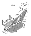
- the pipe handling apparatus 21 for raising pipe P such as casing, drill pipe, collars, or tubing up to a derrick floor 25 of a drilling rig (not shown) and for removing the pipe P from the derrick floor 25.
- the pipe P is stored in racks 27 on both sides of the apparatus 21.
- the apparatus 21 comprises an elongated frame 29 which supports a trough 31 which may be pivoted upward to an inclined position in alignment with a fixed trough 33 as shown in Figures 1 and 9 or downward to a horizontal position as shown in Figures 5 and 10-13. Hydraulic cylinders 34 are provided for pivoting the trough 31 upward or downward.
- the cylinders are pivotally attached to the frame 29 and their pistons are pivotally attached to the trough 31.
- the rear end of the trough 31 is pivotally coupled to the frame 29 at 35.
- the fixed trough 33 is supported in an inclined position by the derrick floor 25 and support structure 36.
- the trough 31 comprises elongated frame members 37A-37D which support a V-shaped floor 39 along which the pipe P slides.
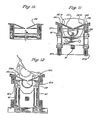
- An intermediate portion 39A of the V-shaped floor 39 is tiltable laterally in either direction when the trough 31 is horizontal, to dump pipe on either side of the apparatus 21 for storage in the racks 27.
- the intermediate position 39A is tiltable by hydraulic cylinders 41.
- the cylinders 41 have their lower ends pivotally coupled to structure 43 which is connected to frame members 37A and 37B and their pistons 41A pivotally coupled to the intermediate portion 39A.
- Figure 12 illustrates the intermediate portion 39A being tilted laterally to the left.
- the cylinders 49 move up and down with the trough 31 as it is pivoted up and down.
- a movable member 49 driven by an endless chain 51 for movement along trough 31 in either direction between its ends 31A and 31B.
- the bottom 53 of the movable member 49 is V-shaped and slides along the floor 39.
- the bottom of the floor 39 has an elongated slot 53 formed therethrough.
- a lug 55 having a thin neck 56 extends from the bottom of the movable member 49. The neck 56 extends through the slot 53 and the lug 55 is connected to the chain 51 below the floor 39.
- Means, not shown, is provided for driving the chain 51 in either direction.
- the trough 31 is located in its horizontal position and the movable member 49 is located at the rear end 31A of the trough 31.
- a length of pipe is transferred from one of the racks 27 into the trough 31 where it rests on the V-shaped floor 39.
- Trough 31 next is pivoted upward to be in alignment with the fixed trough 33.
- the endless chain 51 is driven to move member 49 up the trough 31 to its end 31B.
- the front end 49A of member 49 engages the lower end of the pipe P and pushes the pipe P upward in the troughs 31 and 33 until the pipe overlies the derrick floor.
- the pipe then is lifted into the derrick by cable hoists and or elevators.
- the member 49 is retracted to the rear end 31A or the trough 31; the trough 31 is lowered to a horizontal position; and the process is repeated.
- the trough 31 In moving pipe downward from the derrick floor 25, the trough 31 is raised to be in alignment with the fixed trough 33 and member 49 moved to an upward position along trough 31.
- the cable hoist locates a length of pipe in troughs 33 and 31 and member 49 is moved downward to the lower end of trough 31 to allow the pipe to slide downward in the trough 31 to position the pipe on the intermediate portion 39A of the floor 39.
- the trough 31 then is lowered to a horizontal position and intermediate position 39A is tilted laterally to dump the pipe on either side of the apparatus 21 for storage in one of the racks 27.
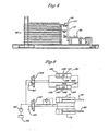
- the pipe transfer system for transferring pipe between the racks 27 and the pipe handling apparatus 21 comprises a pair of aligned arms 61 and 63 located on the side of the pipe handling apparatus 21 and next to one of the pipe racks 27.
- one pair of arms 61 and 63 are shown on the right of the apparatus 21 next to the right rack 27.
- the ends 61A and 63A of arms 61 and 63 are pivotally coupled to the frame 29 at 65 and 67.
- the opposite ends 61B and 63B of arms 61 and 63 may move to an upper position above the catwalk 69 and to a lower position below the catwalk 69 as shown in Figures 1, 2 and 5.
- the arms 61 and_,63 are shown in dashed form in their upper positions.
- a hydraulic system is employed for moving the ends 61B and 63B of arms 61 and 63 together to upward or downward positions or to any level in between.
- the hydraulic system comprises a pair of cylinders 71 and 73 having their ends pivotally coupled to the frame 29 at 75 and 77.
- the pistons 81 and 83 of the cylinders 71 and 73 are pivotally coupled to arms 61 and 63.
- the pistons 81 and 83 are shown pivotally coupled at 85 and 87 to ears 89 and 91 which are connected to arms 61 and 63 respectively.
- the hydraulic system for operating the cylinders 71 and 73 comprises an oil reservoir 93, a pump 95, a four-way directional control valve 97 and appropriate flow lines.
- a stacking and unstacking trough 101 for carrying pipe between the rack 21 and the pipe handling apparatus 21.
- the trough 101 can be pivoted laterally in either direction to allow pipe to be loaded onto and from the trough 101.
- Tilting mechanisms 103 and 105 are provided at each end of the trough 101.
- the ends 61B and 63B of arms 61 and 63 have lugs 107 and 108 secured thereto respectively and which extend laterally outward.
- the lugs 107 and 108 are rotatably coupled to tilting mechanisms 103 and 105 respectively allowing the arms 61 and 63 to move up or down together carrying the length of the trough 101 in a horizontal position.
- tilting mechanisms 103 and l05 is the same.
- Tilting mechanism 103 will be described in detail.
- the lug 107 is rotatably located in an aperture l09 formed through a bearing member 111.
- Member 111 is rotatably mounted on an upper shaft l13 which is supported by two mounts 115 and 117 fixedly secured to the trough 101.
- the shaft 113 freely extends trough apertures 115A and 117A formed through mounts 115 and 117 and through aperture 111A formed through member 111 whereby the mounts 115 and 117 can rotate about the shaft 113 and the shaft 113 can rotate relative to member 111.
- a rotary actuator 121 is fixedly secured to the trough 191 by way of a plate 123 which is secured to the actuator 121 and to the trough 101.
- the actuator 121 has a lower shaft 125 which can be rotated in opposite directions.
- the lower shaft 125 is fixedly secured to a linkage 127 which is coupled to the shaft 113.
- the linkage 127 has an aperture 127A which freely receives the shaft 113 whereby the linkage can rotate about the shaft 113.
- the linkage 127 When the actuator 121 rotates its shaft 125 in one direction, the linkage 127 is rotated causing the linkage to turn about the shaft 113 and hence tilt the actuator 121 and the trough 101.
- the trough 101 is shown in dottedlines tilted laterally in opposite directions. In Figure 3, the actuator 121 is not shown tilting with the trough for purposes of clarity.
- the rotary actuator 12 is a commercially available actuator hydraulically actuated. Referring to Figure 6, it comprises a cylinder 129 having two pistons 131 and 133, with a rack 135 connected between the pistons. The rack 133 engages a pinion 139. The shaft 125 is an extension of the pinion 139. When pressure is imposed on one side of the cylinder 129 it drives the piston and the rack in one direction to rotate the pinion 139 and hence the shaft 125. On the opposite side of the cylinder the pressure is released.
- member 140 is the cylinder for the rotary actuator 141 for the tilting mechanism 105. Actuator 141 is the same as actuator 121.
- the cylinder 140 has two pistons 142 and 143 and a rack 145 connected between the pistons for rotating a pinion 146 from which extends a shaft similar to shaft 107.
- Both actuators of mechanisms 103 and 105 are operated simultaneously by hydraulic fluid from reservoir 93 and pump 95 for driving their shafts in the same direction for tilting the trough 101.
- Four way valve 143 is employed for controlling the direction in which the two actuators 121 and 141 rotate their shafts and hence the direction in which the trough 121 is tilted.
- the arms 61 and 63 and trough 101 operate in the following manner to transfer pipe between the rack 27 and the pipe handling apparatus 21. Assume that pipe is to be transferred from apparatus 21 upward to the rack 27.
- the arms 61 and 63 will be located such that the trough 101 will be just below the catwalk 69 in a non-tilted position whereby the V of the trough 101 will be straight up. In this position, the upper edge of the trough 101 is located close to the catwalk 69 with very little space between the trough edge and the catwalk 69 such that pipe rolling outward on the catwalk 69 will roll into the trough 101.
- the intermediate position 39A of the floor 39 of the trough 31 is tilted laterally to dump a length of pipe onto the catwalk 69.
- the pipe will roll into the trough 101.
- the arms 61 and 63 then are raised simultaneously to raise the trough 1 01 with the trough held in a non-tilted position.
- As the trough is raised, its length will be held horizontal.
- the trough thus will cradle and carry the pipe upward with no longitudinal movement of the pipe in the trough 1 0 1.
- the pipe cannot roll off of the trough, nor can it slide off of the trough longitudinally.
- the arms 61 and 63 and trough 101 operate in the following manner. Assume that pipe is to be transferred from an upper row of pipe on the rack 27 to the pipe handling apparatus 21. The arms 61 and 63 will be located such that the trough 101 will be just below the top row of the pipe on the rack 27 with the trough 101 in a non-tilted position whereby the V of the trough 101 will be straight up. A length of pipe will be pushed into the trough 101. The arms 61 and 63 will then be lowered simultaneously with the trough 101 carrying the length of pipe downward in a horizontal position.
- a pair of arms 61 and 63 and a laterally tiltable trough 101 as described above will be located on both sides of the apparatus 21 for transferring pipe between either rack 27 and the apparatus 21.
- slidable apron 151 removably attachable to the pipe moving device 49 of the pipe handling apparatus 21 for carrying pipe from the derrick floor 25 down the troughs 33 and 31 when there is little or no height differential between the derrick floor 25 and the frame 29 of the pipe handling apparatus 21.
- the apron 151 comprises a V-shaped member slidable on the floor 39 of the trough 31.
- An aperture 153 is formed close to the rear end 151A of the apron 151 into which is fitted a triangular shaped securing member 155 which projects upward from a forward extension of the neck 56 of member 49.
- the aperture 153 does not extend all of the way to the rear end 151A of the apron 151 but is spaced therefrom a short distance.
- the member 153 slants downward toward its forward end whereby the member 155 may be inserted into the aperture 153 by moving the member 49 forward while the apron 151 will ride upward on the member 155 as it moves forward until it reaches full length of the aperture 153 at which time the apron will drop down the the member 155 located in the aperture 153.
- the member 49 When the member 49 is moved forward by the chain, its front end 49A will engage the rear end 151A of the apron and push the apron 151 forward along the trough 31. For drawing pipe from the derrick floor, the apron 151 will be pushed onto the fixed trough 33. A length of pipe will be loaded onto the apron 151 and the member 49 will be moved backward by the chain 51 pulling the apron 151 and hence the pipe backward whereby the pipe may be loaded onto the rack 27. When the member 49 moves backward the rear end 155A of the member 155 engages the rear end 153B of the aperture 153, pulling the apron 151 backward.
- the intermediate or dump portion 39A of the floor 39 of the trough 31 has two elongated apron holding strips 161 and 163 formed along its top outer-edges.
- the outer edges 151B and 151C of the apron slide under the strips 161 and 163 whereby the apron is held to the intermediate or dump portion 39A.
- the apron 151 also will be tilted laterally allowing the pipe to be dumped onto the catwalk 69 for loading onto a rack 27 next to the apparatus 21.
- member 49 will not be located above the dump portion 39A.
- the apron 151 is tilted laterally by the dump portion 39A, its aperture 153 is moved above the member 155.
- the aperture 153 will fit around the member 155 whereby the movable member 49 may push the apron along the trough 31 to the fixed trough 33.
- the apron 151 is used primarily for drawing pipe from the derrick floor for loading on the rack, it is to be understood that it would be used for moving pipe from the rack 27 to the derrick floor.
- the apron 151 also has advantages in that it protects the main troughs 31 and 33 from wear. A teflon like coating may be applied to the underside of the apron 151 to minimize friction.
- the apron 151 may be removed as well as the securing member 155.
- Member 155 may be removably secured to the forward extension of the neck 56 of member 49 by bolts.
- the apron 151 may have a thin neck extending down from its bottom with an enlarged lug attached to the thin neck. The thin neck will extend trough the slot 53 with the enlarged lug located below the floor 39. This arrangement allows the apron 151 to slide on the floor 39 yet holds the apron 151 to the dump portion when it is tilted for dumping purposes.
- the apron 151 may be coupled to the member 49 by securing member 155 to the forward extension of the neck 56 of member 49 through the aperture 153 of the apron 151 when the aperture 153 of the apron 151 is over the forward extension of the neck.
- the apron 151 may be removed by removing member 155 and by sliding the apron forward when the trough 31 is at a slightly inclined position to remove the lower thin neck of the apron from the slot 53 at the forward end of the trough 31.
- the apron 151 will be longer than the length of pipe it will carry.
Landscapes
- Engineering & Computer Science (AREA)
- Geology (AREA)
- Mining & Mineral Resources (AREA)
- Life Sciences & Earth Sciences (AREA)
- General Life Sciences & Earth Sciences (AREA)
- Fluid Mechanics (AREA)
- Environmental & Geological Engineering (AREA)
- Physics & Mathematics (AREA)
- Mechanical Engineering (AREA)
- Geochemistry & Mineralogy (AREA)
- Earth Drilling (AREA)
- Warehouses Or Storage Devices (AREA)
- Specific Conveyance Elements (AREA)
- Stacking Of Articles And Auxiliary Devices (AREA)
- Branching, Merging, And Special Transfer Between Conveyors (AREA)
- Sanitary Device For Flush Toilet (AREA)
- Domestic Plumbing Installations (AREA)
Applications Claiming Priority (4)
| Application Number | Priority Date | Filing Date | Title |
|---|---|---|---|
| US18572780A | 1980-09-10 | 1980-09-10 | |
| US185726 | 1980-09-10 | ||
| US06/185,726 US4382738A (en) | 1980-02-27 | 1980-09-10 | Pipe handling system |
| US185727 | 1988-04-25 |
Related Parent Applications (1)
| Application Number | Title | Priority Date | Filing Date |
|---|---|---|---|
| EP81902672.5 Division | 1981-09-10 |
Publications (1)
| Publication Number | Publication Date |
|---|---|
| EP0139237A1 true EP0139237A1 (en) | 1985-05-02 |
Family
ID=26881410
Family Applications (3)
| Application Number | Title | Priority Date | Filing Date |
|---|---|---|---|
| EP84111355A Withdrawn EP0139237A1 (en) | 1980-09-10 | 1981-09-10 | Apparatus for transferring pipe |
| EP81902673A Expired EP0060295B1 (en) | 1980-09-10 | 1981-09-10 | Tube handling apparatus |
| EP81902672A Expired EP0061473B1 (en) | 1980-09-10 | 1981-09-10 | System for transferring pipe |
Family Applications After (2)
| Application Number | Title | Priority Date | Filing Date |
|---|---|---|---|
| EP81902673A Expired EP0060295B1 (en) | 1980-09-10 | 1981-09-10 | Tube handling apparatus |
| EP81902672A Expired EP0061473B1 (en) | 1980-09-10 | 1981-09-10 | System for transferring pipe |
Country Status (12)
Cited By (4)
| Publication number | Priority date | Publication date | Assignee | Title |
|---|---|---|---|---|
| WO2004092533A1 (en) * | 2003-04-18 | 2004-10-28 | Pipe Wranglers Canada (2004) Inc. | Pipe handling apparatus for presenting sections of pipe to a derrick work floor having a high-speed carriage assembly |
| US7802636B2 (en) | 2007-02-23 | 2010-09-28 | Atwood Oceanics, Inc. | Simultaneous tubular handling system and method |
| US8215888B2 (en) | 2009-10-16 | 2012-07-10 | Friede Goldman United, Ltd. | Cartridge tubular handling system |
| CN104675339A (zh) * | 2015-03-15 | 2015-06-03 | 河北百冠钻井设备有限公司 | 一种钻机钻杆自动输送系统 |
Families Citing this family (12)
| Publication number | Priority date | Publication date | Assignee | Title |
|---|---|---|---|---|
| CA1167833A (en) * | 1980-09-10 | 1984-05-22 | Ingram Corporation | Pipe handling system with apron and stacking arms |
| DE3244896C2 (de) * | 1982-12-04 | 1987-01-08 | Deutsche Schachtbau- und Tiefbohr-Gesellschaft mbH, 4450 Lingen | Transportspeicher |
| GB2158132B (en) * | 1985-05-20 | 1986-12-31 | Ingram Corp | Pipe handling machine |
| US4701687A (en) | 1985-07-30 | 1987-10-20 | Brother Kogyo Kabushiki Kaisha | Controller for energization of a stepper motor |
| DE29921784U1 (de) * | 1999-12-10 | 2001-01-11 | Deutsche Tiefbohr AG, 48455 Bad Bentheim | Gerät zum Transport und zur Handhabung von Rohren und Bohrgestängen |
| US7832974B2 (en) * | 2005-06-01 | 2010-11-16 | Canrig Drilling Technology Ltd. | Pipe-handling apparatus |
| RU2303120C1 (ru) * | 2005-12-19 | 2007-07-20 | Открытое акционерное общество "Центральное конструкторское бюро "Коралл" | Устройство для хранения и перегрузки бурильных и обсадных труб |
| US8845260B2 (en) | 2009-07-29 | 2014-09-30 | Markwater Handling Systems Ltd. | Apparatus and method for handling pipe |
| US10012038B2 (en) | 2014-07-15 | 2018-07-03 | Warrior Rig Technologies Limited | Pipe handling apparatus and methods |
| CN104165031B (zh) * | 2014-08-12 | 2016-10-19 | 四川准达科技有限责任公司 | 钻机自动装卸钻杆装置 |
| CN110436188B (zh) * | 2019-07-05 | 2024-05-17 | 安徽韩华建材科技股份有限公司 | 一种复合地板转移装置 |
| CN114562222B (zh) * | 2022-03-11 | 2025-05-09 | 吉林石油装备技术工程服务有限公司 | 旋转式顶驱作业机一体化装置 |
Citations (8)
| Publication number | Priority date | Publication date | Assignee | Title |
|---|---|---|---|---|
| US2643006A (en) * | 1949-09-28 | 1953-06-23 | William R King | Automatic pipe handler |
| US3254776A (en) * | 1964-04-10 | 1966-06-07 | Socony Mobil Oil Co Inc | Pipe handling and storage apparatus |
| GB1223432A (en) * | 1967-03-29 | 1971-02-24 | James Clay Storm | Well drilling apparatus and method |
| US3810553A (en) * | 1972-08-31 | 1974-05-14 | R Crocker | Pipe handling device |
| US3916500A (en) * | 1972-05-24 | 1975-11-04 | Cicero C Brown | Pipe handling apparatus |
| US4067453A (en) * | 1976-04-19 | 1978-01-10 | Western Gear Corporation | Pipe delivery system |
| US4235566A (en) * | 1978-12-04 | 1980-11-25 | Beeman Archie W | Pipe-conveying catwalk |
| US4347028A (en) * | 1979-09-17 | 1982-08-31 | Automatic Pipe Racker, Inc. | Pipe handling apparatus |
Family Cites Families (9)
| Publication number | Priority date | Publication date | Assignee | Title |
|---|---|---|---|---|
| USRE24907E (en) * | 1960-12-13 | Automatic pipe layer and racker | ||
| US2852147A (en) * | 1954-12-07 | 1958-09-16 | Aubrey F Maydew | Automatic pipe layer and racker |
| US2896796A (en) * | 1957-11-04 | 1959-07-28 | Blaw Knox Co | Pipe lowering device |
| US2954130A (en) * | 1959-07-08 | 1960-09-27 | United States Steel Corp | Lift conveyor for upsetting machine |
| US3159286A (en) * | 1963-10-17 | 1964-12-01 | Sr Richard B Freeman | Drill pipe handling apparatus |
| US3559821A (en) * | 1969-06-19 | 1971-02-02 | Ralph Edward James | Drill pipe handling apparatus |
| US3792783A (en) * | 1971-03-18 | 1974-02-19 | C Brown | Pipe handling system |
| US4208158A (en) * | 1978-04-10 | 1980-06-17 | Franklin Enterprises, Inc. | Auxiliary offshore rig and methods for using same |
| CA1167833A (en) * | 1980-09-10 | 1984-05-22 | Ingram Corporation | Pipe handling system with apron and stacking arms |
-
1981
- 1981-09-09 CA CA000385482A patent/CA1167833A/en not_active Expired
- 1981-09-09 MX MX189106A patent/MX153783A/es unknown
- 1981-09-10 NL NL8120358A patent/NL8120358A/nl unknown
- 1981-09-10 GB GB8213428A patent/GB2093507B/en not_active Expired
- 1981-09-10 DE DE813152309T patent/DE3152309A1/de not_active Withdrawn
- 1981-09-10 JP JP56503146A patent/JPS57501638A/ja active Pending
- 1981-09-10 NL NL8120357A patent/NL8120357A/nl unknown
- 1981-09-10 DE DE813152304T patent/DE3152304A1/de not_active Withdrawn
- 1981-09-10 WO PCT/US1981/001231 patent/WO1982000853A1/en active IP Right Grant
- 1981-09-10 JP JP56503145A patent/JPH0256473B2/ja not_active Expired - Lifetime
- 1981-09-10 EP EP84111355A patent/EP0139237A1/en not_active Withdrawn
- 1981-09-10 WO PCT/US1981/001230 patent/WO1982000852A1/en active IP Right Grant
- 1981-09-10 BR BR8108785A patent/BR8108785A/pt unknown
- 1981-09-10 EP EP81902673A patent/EP0060295B1/en not_active Expired
- 1981-09-10 BR BR8108783A patent/BR8108783A/pt unknown
- 1981-09-10 GB GB8213429A patent/GB2093508B/en not_active Expired
- 1981-09-10 EP EP81902672A patent/EP0061473B1/en not_active Expired
-
1982
- 1982-05-05 NO NO82821479A patent/NO160669C/no unknown
- 1982-05-07 NO NO82821511A patent/NO159199C/no unknown
- 1982-05-07 SE SE8202887A patent/SE452492B/sv not_active IP Right Cessation
- 1982-05-07 SE SE8202888A patent/SE8202888L/xx not_active Application Discontinuation
- 1982-05-10 DK DK207582A patent/DK207582A/da not_active Application Discontinuation
- 1982-05-10 DK DK207682A patent/DK207682A/da unknown
-
1984
- 1984-04-16 GB GB08409801A patent/GB2138471B/en not_active Expired
- 1984-04-17 GB GB08410009A patent/GB2137264B/en not_active Expired
-
1985
- 1985-02-18 GB GB08504058A patent/GB2152112B/en not_active Expired
- 1985-02-18 GB GB08504057A patent/GB2152111B/en not_active Expired
- 1985-02-18 GB GB08504060A patent/GB2152114B/en not_active Expired
- 1985-02-18 GB GB08504059A patent/GB2152113B/en not_active Expired
- 1985-02-18 GB GB08504061A patent/GB2152115B/en not_active Expired
Patent Citations (8)
| Publication number | Priority date | Publication date | Assignee | Title |
|---|---|---|---|---|
| US2643006A (en) * | 1949-09-28 | 1953-06-23 | William R King | Automatic pipe handler |
| US3254776A (en) * | 1964-04-10 | 1966-06-07 | Socony Mobil Oil Co Inc | Pipe handling and storage apparatus |
| GB1223432A (en) * | 1967-03-29 | 1971-02-24 | James Clay Storm | Well drilling apparatus and method |
| US3916500A (en) * | 1972-05-24 | 1975-11-04 | Cicero C Brown | Pipe handling apparatus |
| US3810553A (en) * | 1972-08-31 | 1974-05-14 | R Crocker | Pipe handling device |
| US4067453A (en) * | 1976-04-19 | 1978-01-10 | Western Gear Corporation | Pipe delivery system |
| US4235566A (en) * | 1978-12-04 | 1980-11-25 | Beeman Archie W | Pipe-conveying catwalk |
| US4347028A (en) * | 1979-09-17 | 1982-08-31 | Automatic Pipe Racker, Inc. | Pipe handling apparatus |
Cited By (10)
| Publication number | Priority date | Publication date | Assignee | Title |
|---|---|---|---|---|
| WO2004092533A1 (en) * | 2003-04-18 | 2004-10-28 | Pipe Wranglers Canada (2004) Inc. | Pipe handling apparatus for presenting sections of pipe to a derrick work floor having a high-speed carriage assembly |
| US7802636B2 (en) | 2007-02-23 | 2010-09-28 | Atwood Oceanics, Inc. | Simultaneous tubular handling system and method |
| US8186455B2 (en) | 2007-02-23 | 2012-05-29 | Atwood Oceanics, Inc. | Simultaneous tubular handling system and method |
| US8584773B2 (en) | 2007-02-23 | 2013-11-19 | Atwood Oceanics, Inc. | Simultaneous tubular handling system and method |
| US9410385B2 (en) | 2007-02-23 | 2016-08-09 | Friede Goldman United, Ltd. | Simultaneous tubular handling system |
| US10612323B2 (en) | 2007-02-23 | 2020-04-07 | Friede & Goldman United B.V. | Simultaneous tubular handling system |
| US8215888B2 (en) | 2009-10-16 | 2012-07-10 | Friede Goldman United, Ltd. | Cartridge tubular handling system |
| US8696289B2 (en) | 2009-10-16 | 2014-04-15 | Friede Goldman United, Ltd. | Cartridge tubular handling system |
| US9476265B2 (en) | 2009-10-16 | 2016-10-25 | Friede Goldman United, Ltd. | Trolley apparatus |
| CN104675339A (zh) * | 2015-03-15 | 2015-06-03 | 河北百冠钻井设备有限公司 | 一种钻机钻杆自动输送系统 |
Also Published As
Similar Documents
| Publication | Publication Date | Title |
|---|---|---|
| US4426182A (en) | Tubular handling apparatus | |
| EP0139237A1 (en) | Apparatus for transferring pipe | |
| US4470740A (en) | Apron for pipe handling system | |
| EP0061490B1 (en) | Pipe handling apparatus with trough clamping means | |
| EP1246998B1 (en) | Horizontal pipe handling device | |
| US6079925A (en) | Method and apparatus for lifting oilfield goods to a derrick floor | |
| EP1055048B1 (en) | Apparatus for delivering a tubular to a wellbore | |
| US4453872A (en) | Handling apparatus for pipe and other tubulars | |
| US4129221A (en) | Pipe handling apparatus | |
| US4403898A (en) | Pipe pick-up and laydown machine | |
| US20080138174A1 (en) | Pick-up and lay-down system and method | |
| US4382738A (en) | Pipe handling system | |
| US3795326A (en) | Apparatus for handling drill pipe | |
| US4486137A (en) | Pipe pickup and laydown machine | |
| US4053063A (en) | Apparatus for handling pipe at well site | |
| EP0234880A2 (en) | Pipe handling apparatus and method | |
| WO1983001810A1 (en) | Handling apparatus for pipe and other tubulars | |
| KR860000835B1 (ko) | 파이프 운반장치 | |
| EP3997301B1 (en) | Apparatus for moving cylindrical parts | |
| EP0102349A1 (en) | Pipe handling machine | |
| CA1186300A (en) | Pipe handling machine | |
| GB2158132A (en) | Pipe handling machine | |
| GB2158131A (en) | Pipe handling machine | |
| MXPA06008151A (en) | Single joint drilling system | |
| CA2497830A1 (en) | Pipe rack |
Legal Events
| Date | Code | Title | Description |
|---|---|---|---|
| PUAI | Public reference made under article 153(3) epc to a published international application that has entered the european phase |
Free format text: ORIGINAL CODE: 0009012 |
|
| 17P | Request for examination filed |
Effective date: 19840924 |
|
| AC | Divisional application: reference to earlier application |
Ref document number: 61473 Country of ref document: EP |
|
| AK | Designated contracting states |
Designated state(s): FR |
|
| 17Q | First examination report despatched |
Effective date: 19860820 |
|
| STAA | Information on the status of an ep patent application or granted ep patent |
Free format text: STATUS: THE APPLICATION IS DEEMED TO BE WITHDRAWN |
|
| 18D | Application deemed to be withdrawn |
Effective date: 19870501 |
|
| RIN1 | Information on inventor provided before grant (corrected) |
Inventor name: FRIAS, ROBERT Inventor name: CAIN, TROY DALE |