EP0138729B1 - Air distribution system and method for controlling the same - Google Patents
Air distribution system and method for controlling the same Download PDFInfo
- Publication number
- EP0138729B1 EP0138729B1 EP84630113A EP84630113A EP0138729B1 EP 0138729 B1 EP0138729 B1 EP 0138729B1 EP 84630113 A EP84630113 A EP 84630113A EP 84630113 A EP84630113 A EP 84630113A EP 0138729 B1 EP0138729 B1 EP 0138729B1
- Authority
- EP
- European Patent Office
- Prior art keywords
- conditioned air
- terminal
- amount
- terminals
- controlling
- Prior art date
- Legal status (The legal status is an assumption and is not a legal conclusion. Google has not performed a legal analysis and makes no representation as to the accuracy of the status listed.)
- Expired - Lifetime
Links
- 238000000034 method Methods 0.000 title claims description 18
- 230000001143 conditioned effect Effects 0.000 claims description 24
- 230000001276 controlling effect Effects 0.000 claims description 19
- 230000004044 response Effects 0.000 claims description 4
- 230000001105 regulatory effect Effects 0.000 claims description 3
- 238000005070 sampling Methods 0.000 claims description 3
- 230000003247 decreasing effect Effects 0.000 claims description 2
- 230000000740 bleeding effect Effects 0.000 claims 1
- 230000008569 process Effects 0.000 description 10
- 238000004804 winding Methods 0.000 description 10
- 238000001816 cooling Methods 0.000 description 8
- 238000010438 heat treatment Methods 0.000 description 8
- 230000008859 change Effects 0.000 description 5
- 238000010586 diagram Methods 0.000 description 5
- 230000001186 cumulative effect Effects 0.000 description 3
- 238000013461 design Methods 0.000 description 3
- 238000013459 approach Methods 0.000 description 2
- 230000000704 physical effect Effects 0.000 description 2
- 238000011144 upstream manufacturing Methods 0.000 description 2
- 230000009471 action Effects 0.000 description 1
- 238000004378 air conditioning Methods 0.000 description 1
- 230000004323 axial length Effects 0.000 description 1
- 238000012937 correction Methods 0.000 description 1
- 230000001351 cycling effect Effects 0.000 description 1
- 230000001419 dependent effect Effects 0.000 description 1
- 230000004907 flux Effects 0.000 description 1
- 238000005259 measurement Methods 0.000 description 1
- 230000006903 response to temperature Effects 0.000 description 1
- 230000003068 static effect Effects 0.000 description 1
- 238000012360 testing method Methods 0.000 description 1
Images




Classifications
-
- G—PHYSICS
- G05—CONTROLLING; REGULATING
- G05D—SYSTEMS FOR CONTROLLING OR REGULATING NON-ELECTRIC VARIABLES
- G05D23/00—Control of temperature
- G05D23/19—Control of temperature characterised by the use of electric means
- G05D23/1917—Control of temperature characterised by the use of electric means using digital means
-
- F—MECHANICAL ENGINEERING; LIGHTING; HEATING; WEAPONS; BLASTING
- F24—HEATING; RANGES; VENTILATING
- F24F—AIR-CONDITIONING; AIR-HUMIDIFICATION; VENTILATION; USE OF AIR CURRENTS FOR SCREENING
- F24F11/00—Control or safety arrangements
- F24F11/62—Control or safety arrangements characterised by the type of control or by internal processing, e.g. using fuzzy logic, adaptive control or estimation of values
- F24F11/63—Electronic processing
-
- F—MECHANICAL ENGINEERING; LIGHTING; HEATING; WEAPONS; BLASTING
- F24—HEATING; RANGES; VENTILATING
- F24F—AIR-CONDITIONING; AIR-HUMIDIFICATION; VENTILATION; USE OF AIR CURRENTS FOR SCREENING
- F24F11/00—Control or safety arrangements
- F24F11/70—Control systems characterised by their outputs; Constructional details thereof
- F24F11/72—Control systems characterised by their outputs; Constructional details thereof for controlling the supply of treated air, e.g. its pressure
- F24F11/74—Control systems characterised by their outputs; Constructional details thereof for controlling the supply of treated air, e.g. its pressure for controlling air flow rate or air velocity
- F24F11/77—Control systems characterised by their outputs; Constructional details thereof for controlling the supply of treated air, e.g. its pressure for controlling air flow rate or air velocity by controlling the speed of ventilators
-
- F—MECHANICAL ENGINEERING; LIGHTING; HEATING; WEAPONS; BLASTING
- F24—HEATING; RANGES; VENTILATING
- F24F—AIR-CONDITIONING; AIR-HUMIDIFICATION; VENTILATION; USE OF AIR CURRENTS FOR SCREENING
- F24F11/00—Control or safety arrangements
- F24F11/88—Electrical aspects, e.g. circuits
-
- F—MECHANICAL ENGINEERING; LIGHTING; HEATING; WEAPONS; BLASTING
- F24—HEATING; RANGES; VENTILATING
- F24F—AIR-CONDITIONING; AIR-HUMIDIFICATION; VENTILATION; USE OF AIR CURRENTS FOR SCREENING
- F24F11/00—Control or safety arrangements
- F24F11/30—Control or safety arrangements for purposes related to the operation of the system, e.g. for safety or monitoring
-
- F—MECHANICAL ENGINEERING; LIGHTING; HEATING; WEAPONS; BLASTING
- F24—HEATING; RANGES; VENTILATING
- F24F—AIR-CONDITIONING; AIR-HUMIDIFICATION; VENTILATION; USE OF AIR CURRENTS FOR SCREENING
- F24F13/00—Details common to, or for air-conditioning, air-humidification, ventilation or use of air currents for screening
- F24F13/08—Air-flow control members, e.g. louvres, grilles, flaps or guide plates
- F24F13/082—Grilles, registers or guards
- F24F2013/087—Grilles, registers or guards using inflatable bellows
-
- F—MECHANICAL ENGINEERING; LIGHTING; HEATING; WEAPONS; BLASTING
- F24—HEATING; RANGES; VENTILATING
- F24F—AIR-CONDITIONING; AIR-HUMIDIFICATION; VENTILATION; USE OF AIR CURRENTS FOR SCREENING
- F24F2110/00—Control inputs relating to air properties
- F24F2110/10—Temperature
-
- Y—GENERAL TAGGING OF NEW TECHNOLOGICAL DEVELOPMENTS; GENERAL TAGGING OF CROSS-SECTIONAL TECHNOLOGIES SPANNING OVER SEVERAL SECTIONS OF THE IPC; TECHNICAL SUBJECTS COVERED BY FORMER USPC CROSS-REFERENCE ART COLLECTIONS [XRACs] AND DIGESTS
- Y02—TECHNOLOGIES OR APPLICATIONS FOR MITIGATION OR ADAPTATION AGAINST CLIMATE CHANGE
- Y02B—CLIMATE CHANGE MITIGATION TECHNOLOGIES RELATED TO BUILDINGS, e.g. HOUSING, HOUSE APPLIANCES OR RELATED END-USER APPLICATIONS
- Y02B30/00—Energy efficient heating, ventilation or air conditioning [HVAC]
- Y02B30/70—Efficient control or regulation technologies, e.g. for control of refrigerant flow, motor or heating
Definitions
- the invention relates to an air distribution system according to the preamble of claim 1. It further relates to a method for controlling the same, according to the preamble of claims 5 and 8, respectively. Such a system and method are disclosed in the US-A-3 674 203.
- VAV variable air volume
- the sensor location chosen is about two thirds of the way down the main duct as measured by distance or total pressure drop.
- Space temperatures are not used to control fan speed. Instead, the sensed pressure is fed back to the speed changer through a parallel summing junction/function generator control process.
- the speed changer alters fan speed and thereby fan outlet pressure.
- the duct system splits up the flow, losing more pressure in the branches, is delivered to a VAV terminal control loop which imposes a controlled pressure loss and ultimately influences the space temperature.
- temperature is the variable to be controlled, all of the controls are pressure responsive, and a single pressure sensor is used.
- a single sensor Independent of how well placed it is, a single sensor provides a single reading and it is not an average or otherwise influenced by measurements taken at other locations. Because of this, a single reading cannot give the variable speed control a good view of what is required in the duct under all conditions. Since a full view is not provided, this approach is inherently inaccurate under at least some operating conditions.
- the building operator in order to compensate for inaccuracies, the building operator generally sets the one pressure sensor at a "fat" setting so as to put a comfort factor in and thereby avoid occupant complaints but at the expense of greater energy usage.
- fan volume control is achieved as a result of direct or indirect temperature sensing rather than pressure sensing.
- Temperature sensing can be direct by sensing the set point and actual zone temperature or indirect by sensing a temperature related condition such as the position of the bleed plate of a bleed thermostat.
- a number of sensor locations are used and, while an individual sensor or transducer may be in a poor location due to current system conditions or sensor accuracy range, a plurality of sensor inputs are received by the AT/AH interface controller.
- the AT/AH controller Based upon the information received from the plurality of sensors/transducers, in the duct system, the AT/AH controller makes a decision and sends a corresponding directive to the air handler to cause the fan to maintain the current speed, speed up or slow down.
- the decision is based upon whether or not temperature requirements are satisfied in a plurality of locations, not in response to a single sensed pressure.
- US-A-3 674 203 discloses an air conditioning system including a damper controlled by the static pressure of the supply air to maintain the speed of the air discharge into a zone at a substantial constant velocity.
- thermoelectric transducers/sensors it is to provide an algorithm for taking information from a plurality of thermostatic transducers/sensors, making decisions and controlling the speed of an air handler input responsive thereto.
- temperature is sensed directly or indirectly at selected terminals in the system. Digitized signals representing either a satisfied or unsatisfied condition are sent to the control logic where a decision is made, based upon an algorithm, to increase, decrease or hold the fan speed. This decision signal is sent to the speed changer to change the fan speed, as required. The change in the fan speed causes a change in flow and thereby changes the cooling/heating delivered to the spaces.
- FIG. 1 a prior art system is represented in which a fan 10 is driven at a variable speed by speed changer 12. At the outlet of the fan the pressure in the duct is Pf which drops with distance to a duct pressure of Pd at some point in the common duct, and drops to branch duct pressures of Pd1, Pd2, ... Pdn at some point in the various branches leading to terminals I to n, respectively.
- a common ducfcharacteristic represented by box 13 denotes the physical properties of the common duct with respect to the air flow therethrough.
- a location representative of the conditions in the entire duct is chosen and this location, which corresponds to the duct pressure of Pd, is usually about two thirds of the way down the common duct, as measured by distance or total duct pressure drop, and intermediate the various branch ducts.
- the duct pressure, Pd is sensed at the selected location by pressure sensor 14, amplified by amplifier 15 and a 118751-201 491 Pa (3-15 psig) signal representative thereof is supplied as an inlet to summing junctions 16 and 17.
- a second input representative of a high pressure set point is supplied to summing junction 16 and, if the signal from pressure sensor 14 via amplifier 15 is greater than the signal representative of the high pressure set point, a positive signal is supplied to function generator 18 which, in turn, sends an electrical signal to speed changer 12 instructing it to decrease the speed of the fan 10.
- function generator 18 In a typical function generator, no signal is given until a certain level input signal is received, e.g. the signal from amplifier 15 must be greater than the high pressure set point for function generator 18 to furnish a signal to speed changer 12.
- a second input representative of a low pressure set point is supplied to summing junction 17 and, if the signal from pressure sensor 14 via amplifier 15 is less than the signal representative of the low pressure set point, a negative signal is supplied to function generator 19 which, in turn, sends an electrical signal to speed changer 12 instructing it to increase the speed of fan 10.
- the output of fan 10 is ultimately supplied to a plurality of branch ducts, each having their own duct characteristic represented by boxes 20-1, 20-2,... 20-n denoting the physical properties of the respective branch ducts by pressures Pd1, Pd2 ... Pdn.
- Each branch has at least one VAV terminal local loop, numbered 22-1 to n, respectively, each receiving a temperature set point, Tspl to Tspn, respectively.
- the VAV terminal local loops 22-1 to n physically comprise the terminals responsive to the respective temperature set points Tspl to Tspn and the actual zone temperatures.
- the VAV terminal loops 22-1 to n control the flow of conditioned air from terminals 1 to n to the rooms or zones. In a typical VAV terminal local loop, the conditioned air passes into the room or zone by passing through an opening formed between two inflatable bellows in the terminal.
- the bellows are supplied with duct air via a pressure regulator and the degree of inflation, and thereby the opening size, is controlled by a bleed thermostat which bleeds the bellows inflation air to the atmosphere at a controlled rate according to the bleed thermostat set point and room/zone temperature.
- the resultant zone temperatures for each zone are Tt1, Tt2, ... Ttn, respectively.
- the Figure 2 system tests the zone temperatures at the VAV terminal local loops 22-1 to n rather than the main duct pressure upstream of at least some of the VAV terminal local loops 22-1 to n; (2) the Figure 2 system uses a plurality of temperature sensors rather than a single pressure sensor; and (3) the Figure 2 system uses a control logic based upon zone conditions for all of the zone rather than a single main duct sensor that may or may not be currently representative of system conditions.
- the control logic of controller 26 processes the signals Dt1, Dt2 ... Dtn as set forth in Figure 3. More specifically, the process starts by the controller sampling all of the thermostatic transducer signals Dt1, Dt2 ... Dtn in the duct system. All of the signals are compared with each other in a series of Boolean operations in order to determine how many of the transducers are in air spaces which are not satisfied i.e. need more heating/cooling. The number of dissatisfied spaces is determined and if it is at or past a set high limit, H, the controller 26 sends a signal to the fan 10 to increase speed by a predetermined increment and, after a pause of X1 minutes, returns to START and initiates the decision process over again.
- the controller checks to see if the number of dissatisfied spaces is equal to, or less than, a set low limit, L and, if so, the controller sends a signal to the fan to decrease fan speed by a predetermined increment and, after a pause of X2 minutes returns to START and initiates the decision process over again. If the number of dissatisfied terminals is more than L but less than H, no fan speed control signal is sent and the controller pauses for an indefinite amount of time until an "event", in the form of the sensing of a change in status of any of the transducers, occurs. When the change in status of a terminal to/from satisfied is sensed the controller returns to START and initiates the decision process over again.
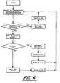
- FIG. 4 An alternative control logic function is illustrated in Figure 4. As in the embodiment of Figure 3, the process starts by the controller sampling all of the thermostatic transducer signals in a series of Boolean operations. If any of the terminals are not satisfied, the controller 26 sends a signal to the fan 10 to increase speed by a predetermined increment and, after a pause of X1 minutes, returns to START and initiates the decision process over again. If none of the terminals are dissatisfied, then 1 is added to the counter flag, Ke, and Ke is compared with Kesp, the counter set point.
- Ke is greater than Kesp
- the controller 26 sends a signal to the fan 10 to decrease speed by a predetermined increment and, after a pause of X2 minutes, resets Ke to ⁇ , returns to START and initiates the decision process over again. If there are no dissatisfied thermostats and Ke is not greater than Kesp then the fan speed is held and, after a pause of X3 minutes, the controller returns to START and initiates the decision process again.
- the fan speed is maintained for a number of time periods, each of a duration of X3 minutes, determined by the value of Kesp, before the fan speed is decreased. This approach reduces the cycling of the fan speed when the system is at or near the bare minimum.
- FIG. 5 generally illustrates each of the VAV terminal local control loops 22-1 to n of the Figure 2 embodiment.
- the transducer 24-1 supplies information about the temperature in the airspace to the AT/AH interface controller 26.
- the controller 26 takes this information from transducers 24-1 to n, makes a decision and sends a directive to the speed changer to hold, increase or decrease the fan speed. In this manner, the controller 26 is provided with information as to the duct system's temperature diversity in order to provide the basis for an intelligent decision.
- the numeral 100 generally designates a thermostat including a thermostatic transducer.
- the thermostat 100 includes a housing 102 having an opening formed in the lower portion thereof for passage of room air therethrough into the interior of the housing.
- a "U" shaped bimetallic element 104 is mounted within housing 102 on an adjustment block 106.
- bimetallic element 104 is preferably provided with a plurality of perforations (not illustrated) extending through-out its axial length in legs 104a and b thereof. By providing the perforations, the width of bimetallic element 104 can be made only slightly less than the interior of housing 102.
- the adjustment block 106 which mounts bimetallic element 104 is slidably mounted within housing 102 for vertical movement relative thereto.
- Spring 108 provides a bias to block 106 against temperature adjustment cams 110 formed on adjustment shaft 114.
- Shaft 114 is journalled in a calibration block which is secured to housing 102 by a calibration screw (not illustrated).
- a rotational force may be applied manually or otherwise, to shaft 114 via adjustment lever 116 which is affixed to the end thereof.
- Leg 104b, block 106, cams 110, shaft 114 and lever 116 together make up a first linkage.
- Lever 120 is pivotable about shaft 124 and journalled within the side walls of housing 102 to convert the vertical movement of bimetallic element 104 caused by temperature variations into horizontal movement.
- a bleed plate 130 having an opening 132 therein is provided to override bleed port 134 formed within housing 102.
- Lever 120 is therefore provided with arms 121 and 122 of unequal lengths measured from the axis of shaft 124. The short arm, 121, contacts leg 104a of bimetallic element 104 while the long arm, 122, contacts bleed plate 130. This provides a relatively large horizontal movement of the bleed plate 130 to compensate for the relatively small vertical movement resulting from the use of a short bimetallic element.
- bimetallic element 104 has a greater thickness than bimetallic elements normally employed in a thermostat of this type.
- a spring 140 is suitably affixed to housing 102 and is provided to bias plate 130 toward lever 120.
- Leg 104a, shaft 124, arms 121 and 122 of lever 120 and bleed plate 130 together make up a second linkage.
- Bleed port 134 communicates with an air passage 142 within housing 102.
- An opening 144 within housing 102, communicating with passage 142, is provided for receiving a suitable pressure regulator to provide regulated control pressure to bleed port 134.
- a suitable pressure regulator for a description of a suitable pressure regulator, reference may be had to United States Patent No. 3 434 409. Air is bled from the regulator through bleed port 134 to provide a variable air pressure at the bladders or bellows (not illustrated) controlling the inflation of the bellows and thereby the flow of conditioned air into the room/z6ne in response to temperature variations in the area being treated.
- the thermostat portion of the structure designated by numeral 100 is conventional for use as a bleed thermostat.
- the bleed plate 130 is provided with an extension 130a having a magnetic member 130b thereon for use as a transformer core and is a movable core for differential transformer 146.
- the extension 130a extends into transformer 146 which has two secondary windings 148 and 152 and primary winding 150.
- Primary winding 150 which is located between and overlapped by the two secondary windings 148 and 152 around the core 130b carried by extension 130a, is connected to a source of AC power.
- the two spaced apart secondary windings 148 and 152 are connected by separate leads 153 and 154 at one of their ends and a common lead 155 from their opposite ends to a diode detector circuit 160.
- a diode detector circuit 160 When the core defined by member 130b is moved closer to one secondary winding than the other, it couples more magnetic flux into one winding, and the output from this secondary winding, or the difference between the two secondary windings, is varied by an amount proportional to the amount of linear travel of the core 130b.
- the alternating current signal from the secondary windings is converted to a direct current signal by diode detector circuit 160.
- This voltage, Xov is supplied to thermostatic transducer 24-1 and represents the position of the bleed plate extension 130a.
- the position of the bleed plate extension 130a is also indicative-of the position of bleed plate 130 and opening 132 and therefore provides a reading of terminal satisfaction/dissatisfaction.
- a terminal is satisfied unless bleed port 134 is in full registration with opening 132.
- Full registration of port 134 with opening 132 would imply that the temperature in the zone is higher than the set point in the cooling mode or less than the set point in the heating mode.
- branch duct pressure, Pd1 is supplied as a first input to the bellows for determining the bellows orifice characteristic represented by box 42.
- the bellows inflation pressure, Pb1 is supplied as a second input to the bellows for determining bellows orifice characteristic 42.
- the bellows orifice characteristic in the form of the bellows orifice cross sectional area is thus actually determined by the bellows inflation which results from the difference between duct pressure, Pd1, and a modified duct pressure in the form of bellows supply or inflation pressure, Pb1.
- the branch duct pressure, Pd1 forces supply air across the bellows orifice cross sectional area to result in an output CFM.
- the output CFM representative of the flow through the terminal is supplied to room 43.
- the CFM In determining the heat balance of room 43 the CFM is supplied as a first input to the room space represented by block 44 and the difference, A T, between the supply air temperature, Tsa, and the temperature of the space near the terminal, Tt1, acts on the CFM as a second input to the room space represented by block 44 which has an "output" Qin, which represents the cooling/heating delivered to the room 43.
- Qin is equal to the product of CFM, the density of the air, the specific heat of the air and A T.
- the room heat balance is represented by block 46 which receives a first input, Qin, representing the cooling/heating delivered to the room and a second input, Qload, representing the heating/cooling load of the room.
- Qin representing the cooling/heating delivered to the room
- Qload representing the heating/cooling load of the room.
- the difference between Qin and Qload is Qnet which represents the net or accumulated heating/cooling in the room.
- Qnet is acted upon by the room characteristic represented by box 47 which is the product of room mass, thermal capacitance, and the derivative of temperature with respect to time (dT/dt) which results in temperature Tt1 which is supplied as a first input to subtractor 50.
- the supply air temperature, Tsa is supplied as a second input to subtractor 50 and the output, A T, is supplied as an input to room space 44 as described above.
- the space temperature near the terminal, Tt1 acts on the bimetal, 104, of the bleed thermostat which positions itself accordingly in response to thermal expansion due to the bimetal expansion coefficient represented by box 52 and the bimetal position, Xt, is supplied by a first input to summing junction 54.
- the temperature set point, Tspl, of the zone is supplied by positioning lever 116 ( Figure 7) and serves as an input to thermostat dial 62.
- the thermostat dial 62 produces an output, Xtab, representing the scale graduation position of the bleed thermostat 100 which positions the first linkage 64 of the bleed thermostat 100 made up of members 104b, 106,110,114 and 116.
- the linkage 64 has an output, Xsp, representing the position of bleed thermostat bleed plate opening 132 which is supplied as a second input to summing junction 54.
- the output of summing junction 54 is Xb and represents the net position of the first linkage 64 and is supplied to the second linkage 70 made up of members 104a, 124, 120 and 130 and causes second linkage 70 to move a distance Xo. Movement of linkage 70 causes the movement of bleed plate 130 containing opening 132 and extension 130a.
- the movement Xo of bleed plate extension 130a is converted to a voltage Xov, as discussed above with respect to Figure 8, and is supplied as a first input to summing junction 72 in thermostatic transducer 24-1.
- a second input Xmax represents the position of bleed plate 130 which will permit the maximum bleed through opening 132 and is supplied as the second input to summing junction 72.
- the output Xnet of summing junction 72 represents the difference between the current position of bleed plate 130 and the critical position which allows the maximum bleed flow and thus represents how much more the opening 132 can be uncovered.
- Xnet is supplied to function generator74 which, responsive thereto produces a binary (digital) output, DT1, of either ⁇ or 1 which is supplied to controller 26 and indicates whether or not the terminal is satisfied.
- the control logic of controller 26 receives the outputs from all of the transducers 24-1 to n which are located in terminals around the duct system.
- the inputs are used according to the selected algorithm to provide the decision basis for controlling the air handler/fan.
- the movement, Xo, of linkage 70 also produces a slot orifice geometric relation represented by box 56 which has an output, Ao, representative of the orifice cross-sectional area which is equal to Xo times the mean length, or diameter depending upon the shape, of opening 132 and is supplied as s first input for determining the slot orifice characteristic represented by block 58.
- the pressure regulator set point (in CFM), CFMsp, is supplied as a first input to processor 60 and branch duct pressure Pd1 is supplied as a second input which establishes a pressure regulator coefficient relationship and produces an output, Pi, representative of an intermediate pressure, which is supplied as a second input to block 58.
- an output, Pb1 is produced which is representative of the bellows inflation pressure and is supplied to determine bellows orifice characteristic 42, as described above.
Landscapes
- Engineering & Computer Science (AREA)
- Mechanical Engineering (AREA)
- General Engineering & Computer Science (AREA)
- Chemical & Material Sciences (AREA)
- Combustion & Propulsion (AREA)
- Physics & Mathematics (AREA)
- Signal Processing (AREA)
- Fuzzy Systems (AREA)
- Mathematical Physics (AREA)
- Fluid Mechanics (AREA)
- General Physics & Mathematics (AREA)
- Automation & Control Theory (AREA)
- Air Conditioning Control Device (AREA)
- Control Of Temperature (AREA)
Description
- The invention relates to an air distribution system according to the preamble of
claim 1. It further relates to a method for controlling the same, according to the preamble of claims 5 and 8, respectively. Such a system and method are disclosed in the US-A-3 674 203. - In conventional variable air volume (VAV) systems which are capable of variable output by varying the fan speed, positioning the inlet guide vanes or by controlling the pitch of an axial fan, fan control is achieved through the use of a single pressure sensor which is located somewhere in the main duct line. The pressure sensor sends an input directly to the fan control such as a variable speed drive of an air handler unit to cause the speed to increase, decrease or remain constant. Thus, if the pressure at the sensor location is too high, a "decrease" signal is sent and, if it is too low, an "increase" signal is sent. The location of the sensor is carefully chosen in order that the pressure sensed is most closely representative of the overall system pressure distribution over the whole load range. Ordinarily, the sensor location chosen is about two thirds of the way down the main duct as measured by distance or total pressure drop. Space temperatures are not used to control fan speed. Instead, the sensed pressure is fed back to the speed changer through a parallel summing junction/function generator control process. The speed changer alters fan speed and thereby fan outlet pressure. There is a pressure loss in the remaining main/common duct downstream of the pressure sensor. The duct system splits up the flow, losing more pressure in the branches, is delivered to a VAV terminal control loop which imposes a controlled pressure loss and ultimately influences the space temperature. Thus, although temperature is the variable to be controlled, all of the controls are pressure responsive, and a single pressure sensor is used. So, even if the pressure sensor is located at the point where the sensor will give the "best" representation of the overall duct pressure distribution at design flow, when there is off design flow and when the VAV terminals on one side of the duct system close off, however, the "best" spot changes to another location. As a result, the sensor may be inaccurate in its representation of duct pressure distribution under off-design conditions as well as those due to normal changes during the day.
- Independent of how well placed it is, a single sensor provides a single reading and it is not an average or otherwise influenced by measurements taken at other locations. Because of this, a single reading cannot give the variable speed control a good view of what is required in the duct under all conditions. Since a full view is not provided, this approach is inherently inaccurate under at least some operating conditions. In addition, in order to compensate for inaccuracies, the building operator generally sets the one pressure sensor at a "fat" setting so as to put a comfort factor in and thereby avoid occupant complaints but at the expense of greater energy usage.
- In a VAV system employing an air terminal-air handler (AT/AH) interface controller, fan volume control is achieved as a result of direct or indirect temperature sensing rather than pressure sensing. Temperature sensing can be direct by sensing the set point and actual zone temperature or indirect by sensing a temperature related condition such as the position of the bleed plate of a bleed thermostat. Unlike conventional systems, a number of sensor locations are used and, while an individual sensor or transducer may be in a poor location due to current system conditions or sensor accuracy range, a plurality of sensor inputs are received by the AT/AH interface controller. Based upon the information received from the plurality of sensors/transducers, in the duct system, the AT/AH controller makes a decision and sends a corresponding directive to the air handler to cause the fan to maintain the current speed, speed up or slow down. The decision, however is based upon whether or not temperature requirements are satisfied in
a plurality of locations, not in response to a single sensed pressure. - US-A-3 674 203 discloses an air conditioning system including a damper controlled by the static pressure of the supply air to maintain the speed of the air discharge into a zone at a substantial constant velocity.
- It is an object of this invention to achieve a greater fan energy savings through more responsive fan output control.
- It is a further object of this invention to provide more information to an AT/AH interface controller and thereby better matching of fan output to demand.
- It is an additional object of this invention to permit an air handling unit to run at lower speeds or power settings, when appropriate, thus saving energy.
- These objects are achieved by the system and method for controlling the distribution of conditioned air claimed in the
independent claims 1, 5 and 8. Embodiments of the invention are claimed in the dependent claims. - According to one aspect of this invention it is to provide an algorithm for taking information from a plurality of thermostatic transducers/sensors, making decisions and controlling the speed of an air handler input responsive thereto. These objects, and the others as will become apparent hereinafter, are accomplished by the present invention.
- Basically, temperature is sensed directly or indirectly at selected terminals in the system. Digitized signals representing either a satisfied or unsatisfied condition are sent to the control logic where a decision is made, based upon an algorithm, to increase, decrease or hold the fan speed. This decision signal is sent to the speed changer to change the fan speed, as required. The change in the fan speed causes a change in flow and thereby changes the cooling/heating delivered to the spaces.
- For a fuller understanding of the present invention, reference should now be made to the following detailed description thereof taken in conjunction with the accompanying drawings wherein:
- Figure 1 is a functional block diagram of a prior art control system;
- Figure 2 is a functional block diagram of the control system of the present invention;
- Figure 3 is a flow diagram showing the operation of the control logic;
- Figure 4 is a flow diagram showing an alternative operation of the control logic;
- Figure 5 is a functional block diagram of a VAV terminal local control loop;
- Figure 6 is a top view of a thermostatic transducer;
- Figure 7 is a sectional view taken along line Vll-VII of Figure 6; and
- Figure 8 is a schematic representation of the thermostatic transducer.
- In Figure 1 a prior art system is represented in which a
fan 10 is driven at a variable speed byspeed changer 12. At the outlet of the fan the pressure in the duct is Pf which drops with distance to a duct pressure of Pd at some point in the common duct, and drops to branch duct pressures of Pd1, Pd2, ... Pdn at some point in the various branches leading to terminals I to n, respectively. A common ducfcharacteristic represented bybox 13 denotes the physical properties of the common duct with respect to the air flow therethrough. A location representative of the conditions in the entire duct is chosen and this location, which corresponds to the duct pressure of Pd, is usually about two thirds of the way down the common duct, as measured by distance or total duct pressure drop, and intermediate the various branch ducts. The duct pressure, Pd, is sensed at the selected location by pressure sensor 14, amplified byamplifier 15 and a 118751-201 491 Pa (3-15 psig) signal representative thereof is supplied as an inlet to summingjunctions junction 16 and, if the signal from pressure sensor 14 viaamplifier 15 is greater than the signal representative of the high pressure set point, a positive signal is supplied to functiongenerator 18 which, in turn, sends an electrical signal tospeed changer 12 instructing it to decrease the speed of thefan 10. In a typical function generator, no signal is given until a certain level input signal is received, e.g. the signal fromamplifier 15 must be greater than the high pressure set point forfunction generator 18 to furnish a signal tospeed changer 12. - Similarly, a second input representative of a low pressure set point is supplied to summing
junction 17 and, if the signal from pressure sensor 14 viaamplifier 15 is less than the signal representative of the low pressure set point, a negative signal is supplied tofunction generator 19 which, in turn, sends an electrical signal tospeed changer 12 instructing it to increase the speed offan 10. The output offan 10 is ultimately supplied to a plurality of branch ducts, each having their own duct characteristic represented by boxes 20-1, 20-2,... 20-n denoting the physical properties of the respective branch ducts by pressures Pd1, Pd2 ... Pdn. (Note thatbranch duct * 1, 20-1, is illustrated as branching off upstream of the location of pressure Pd.) Each branch has at least one VAV terminal local loop, numbered 22-1 to n, respectively, each receiving a temperature set point, Tspl to Tspn, respectively. The VAV terminal local loops 22-1 to n physically comprise the terminals responsive to the respective temperature set points Tspl to Tspn and the actual zone temperatures. The VAV terminal loops 22-1 to n control the flow of conditioned air fromterminals 1 to n to the rooms or zones. In a typical VAV terminal local loop, the conditioned air passes into the room or zone by passing through an opening formed between two inflatable bellows in the terminal. The bellows are supplied with duct air via a pressure regulator and the degree of inflation, and thereby the opening size, is controlled by a bleed thermostat which bleeds the bellows inflation air to the atmosphere at a controlled rate according to the bleed thermostat set point and room/zone temperature. The resultant zone temperatures for each zone are Tt1, Tt2, ... Ttn, respectively. - From the foregoing description of the Figure 1 system it follows that the only feedback from the terminals to fan 10 and
speed changer 12 is indirectly through the cumulative changes in duct pressure Pd due to the action of VAV terminal loops I to n in controlling air flow in the individual terminals by controlling the inflation of the various bellows. It is the cumulative effect of VAV terminal loops I to n and the speed offan 10 which results in Pd. This cumulative effect is, however, not responsive to individual terminal conditions and the pressure Pd is, often, an incorrect representation of system needs. - In Figure 2, starting with
speed changer 12,fan 10 and continuing through VAV terminal local loops 22-1 to n, the control system is the same as that of Figure 1 except for the absence of pressure sensor or transducer 14. The resultant zone temperatures of Tt1 ... Ttn, respectively, act on thermostatic transducers 24-1, 24-2 ... 24-n which are located in selected terminals. The transducers 24-1, 24.2... 24-n produce binary form digital signals Dt1, Dt2 ... Dtn, indicating terminal temperature satisfaction or not, which are supplied as inputs tocontroller 26. A terminal is considered to be satisfied unless the bleed thermostat is fully open, to cause maximum bellows opening, implying that the zone temperature is greater than the set point in the cooling mode or less than the set point in the heating mode. Thecontroller 26 contains control logic which acts in response to these inputs to send an increase signal, a decrease signal or no signal to thespeed changer 12 to increase, decrease or maintain the fan speed. Thecontroller 26 periodically samples the input signals to permit the system to respond to corrections. - In comparing the systems of Figure 1 and 2 it is apparent that: (1) the Figure 2 system tests the zone temperatures at the VAV terminal local loops 22-1 to n rather than the main duct pressure upstream of at least some of the VAV terminal local loops 22-1 to n; (2) the Figure 2 system uses a plurality of temperature sensors rather than a single pressure sensor; and (3) the Figure 2 system uses a control logic based upon zone conditions for all of the zone rather than a single main duct sensor that may or may not be currently representative of system conditions.
- The control logic of
controller 26 processes the signals Dt1, Dt2 ... Dtn as set forth in Figure 3. More specifically, the process starts by the controller sampling all of the thermostatic transducer signals Dt1, Dt2 ... Dtn in the duct system. All of the signals are compared with each other in a series of Boolean operations in order to determine how many of the transducers are in air spaces which are not satisfied i.e. need more heating/cooling. The number of dissatisfied spaces is determined and if it is at or past a set high limit, H, thecontroller 26 sends a signal to thefan 10 to increase speed by a predetermined increment and, after a pause of X1 minutes, returns to START and initiates the decision process over again. If the number- of dissatisfied terminals is less than H, the controller then checks to see if the number of dissatisfied spaces is equal to, or less than, a set low limit, L and, if so, the controller sends a signal to the fan to decrease fan speed by a predetermined increment and, after a pause of X2 minutes returns to START and initiates the decision process over again. If the number of dissatisfied terminals is more than L but less than H, no fan speed control signal is sent and the controller pauses for an indefinite amount of time until an "event", in the form of the sensing of a change in status of any of the transducers, occurs. When the change in status of a terminal to/from satisfied is sensed the controller returns to START and initiates the decision process over again. - An alternative control logic function is illustrated in Figure 4. As in the embodiment of Figure 3, the process starts by the controller sampling all of the thermostatic transducer signals in a series of Boolean operations. If any of the terminals are not satisfied, the
controller 26 sends a signal to thefan 10 to increase speed by a predetermined increment and, after a pause of X1 minutes, returns to START and initiates the decision process over again. If none of the terminals are dissatisfied, then 1 is added to the counter flag, Ke, and Ke is compared with Kesp, the counter set point. If Ke is greater than Kesp, then thecontroller 26 sends a signal to thefan 10 to decrease speed by a predetermined increment and, after a pause of X2 minutes, resets Ke to Φ, returns to START and initiates the decision process over again. If there are no dissatisfied thermostats and Ke is not greater than Kesp then the fan speed is held and, after a pause of X3 minutes, the controller returns to START and initiates the decision process again. In this embodiment, when all of the terminals are satisfied the fan speed is maintained for a number of time periods, each of a duration of X3 minutes, determined by the value of Kesp, before the fan speed is decreased. This approach reduces the cycling of the fan speed when the system is at or near the bare minimum. - The details of exemplary VAV terminal local control loop 22-1 of Figure 2 is illustrated in greater detail in Figure 5. However, Figure 5 generally illustrates each of the VAV terminal local control loops 22-1 to n of the Figure 2 embodiment. As evident from the foregoing description, the transducer 24-1 supplies information about the temperature in the airspace to the AT/
AH interface controller 26. Thecontroller 26 takes this information from transducers 24-1 to n, makes a decision and sends a directive to the speed changer to hold, increase or decrease the fan speed. In this manner, thecontroller 26 is provided with information as to the duct system's temperature diversity in order to provide the basis for an intelligent decision. - In Figure 6 and 7 the numeral 100 generally designates a thermostat including a thermostatic transducer. As is conventional, the
thermostat 100 includes ahousing 102 having an opening formed in the lower portion thereof for passage of room air therethrough into the interior of the housing. A "U" shapedbimetallic element 104 is mounted withinhousing 102 on anadjustment block 106. In order to assure maximum contact of room air with thebimetallic element 104 and to provide a bimetallic element large enough to actuate the movable members of thethermostatic transducer 100,bimetallic element 104 is preferably provided with a plurality of perforations (not illustrated) extending through-out its axial length inlegs 104a and b thereof. By providing the perforations, the width ofbimetallic element 104 can be made only slightly less than the interior ofhousing 102. - The
adjustment block 106 which mountsbimetallic element 104 is slidably mounted withinhousing 102 for vertical movement relative thereto. Spring 108 provides a bias to block 106 againsttemperature adjustment cams 110 formed onadjustment shaft 114.Shaft 114 is journalled in a calibration block which is secured tohousing 102 by a calibration screw (not illustrated). A rotational force may be applied manually or otherwise, toshaft 114 viaadjustment lever 116 which is affixed to the end thereof.Leg 104b, block 106,cams 110,shaft 114 andlever 116 together make up a first linkage. -
Lever 120 is pivotable aboutshaft 124 and journalled within the side walls ofhousing 102 to convert the vertical movement ofbimetallic element 104 caused by temperature variations into horizontal movement. Ableed plate 130 having anopening 132 therein is provided to overridebleed port 134 formed withinhousing 102. To obtain a compact thermostat, a short bimetallic element is utilized.Lever 120 is therefore provided witharms shaft 124. The short arm, 121,contacts leg 104a ofbimetallic element 104 while the long arm, 122, contacts bleedplate 130. This provides a relatively large horizontal movement of thebleed plate 130 to compensate for the relatively small vertical movement resulting from the use of a short bimetallic element. To obtain the necessary force againstarm 121,bimetallic element 104 has a greater thickness than bimetallic elements normally employed in a thermostat of this type. Aspring 140 is suitably affixed tohousing 102 and is provided tobias plate 130 towardlever 120.Leg 104a,shaft 124,arms lever 120 and bleedplate 130 together make up a second linkage. - Bleed
port 134 communicates with anair passage 142 withinhousing 102. Anopening 144 withinhousing 102, communicating withpassage 142, is provided for receiving a suitable pressure regulator to provide regulated control pressure to bleedport 134. For a description of a suitable pressure regulator, reference may be had to United States Patent No. 3 434 409. Air is bled from the regulator throughbleed port 134 to provide a variable air pressure at the bladders or bellows (not illustrated) controlling the inflation of the bellows and thereby the flow of conditioned air into the room/z6ne in response to temperature variations in the area being treated. - The thermostat portion of the structure designated by
numeral 100, to the extent to which it has been described, is conventional for use as a bleed thermostat. To convert the thermostat into a transducer, thebleed plate 130 is provided with anextension 130a having amagnetic member 130b thereon for use as a transformer core and is a movable core fordifferential transformer 146. Referring now to Figure 8, theextension 130a extends intotransformer 146 which has twosecondary windings secondary windings core 130b carried byextension 130a, is connected to a source of AC power. The two spaced apartsecondary windings separate leads common lead 155 from their opposite ends to adiode detector circuit 160. When the core defined bymember 130b is moved closer to one secondary winding than the other, it couples more magnetic flux into one winding, and the output from this secondary winding, or the difference between the two secondary windings, is varied by an amount proportional to the amount of linear travel of the core 130b. The alternating current signal from the secondary windings is converted to a direct current signal bydiode detector circuit 160. This voltage, Xov, is supplied to thermostatic transducer 24-1 and represents the position of thebleed plate extension 130a. It follows that the position of thebleed plate extension 130a is also indicative-of the position ofbleed plate 130 andopening 132 and therefore provides a reading of terminal satisfaction/dissatisfaction. A terminal is satisfied unlessbleed port 134 is in full registration withopening 132. Full registration ofport 134 withopening 132 would imply that the temperature in the zone is higher than the set point in the cooling mode or less than the set point in the heating mode. - Referring now to Figure 5, branch duct pressure, Pd1 is supplied as a first input to the bellows for determining the bellows orifice characteristic represented by
box 42. The bellows inflation pressure, Pb1, is supplied as a second input to the bellows for determining bellows orifice characteristic 42. The bellows orifice characteristic in the form of the bellows orifice cross sectional area is thus actually determined by the bellows inflation which results from the difference between duct pressure, Pd1, and a modified duct pressure in the form of bellows supply or inflation pressure, Pb1. The branch duct pressure, Pd1, forces supply air across the bellows orifice cross sectional area to result in an output CFM. The output CFM, representative of the flow through the terminal is supplied toroom 43. In determining the heat balance ofroom 43 the CFM is supplied as a first input to the room space represented byblock 44 and the difference, A T, between the supply air temperature, Tsa, and the temperature of the space near the terminal, Tt1, acts on the CFM as a second input to the room space represented byblock 44 which has an "output" Qin, which represents the cooling/heating delivered to theroom 43. Qin is equal to the product of CFM, the density of the air, the specific heat of the air and A T. The room heat balance is represented byblock 46 which receives a first input, Qin, representing the cooling/heating delivered to the room and a second input, Qload, representing the heating/cooling load of the room. The difference between Qin and Qload is Qnet which represents the net or accumulated heating/cooling in the room. Qnet is acted upon by the room characteristic represented by box 47 which is the product of room mass, thermal capacitance, and the derivative of temperature with respect to time (dT/dt) which results in temperature Tt1 which is supplied as a first input tosubtractor 50. The supply air temperature, Tsa, is supplied as a second input tosubtractor 50 and the output, A T, is supplied as an input toroom space 44 as described above. The space temperature near the terminal, Tt1, acts on the bimetal, 104, of the bleed thermostat which positions itself accordingly in response to thermal expansion due to the bimetal expansion coefficient represented bybox 52 and the bimetal position, Xt, is supplied by a first input to summing junction 54. The temperature set point, Tspl, of the zone is supplied by positioning lever 116 (Figure 7) and serves as an input tothermostat dial 62. Thethermostat dial 62 produces an output, Xtab, representing the scale graduation position of thebleed thermostat 100 which positions thefirst linkage 64 of thebleed thermostat 100 made up ofmembers 104b, 106,110,114 and 116. Thelinkage 64 has an output, Xsp, representing the position of bleed thermostat bleed plate opening 132 which is supplied as a second input to summing junction 54. The output of summing junction 54 is Xb and represents the net position of thefirst linkage 64 and is supplied to thesecond linkage 70 made up ofmembers second linkage 70 to move a distance Xo. Movement oflinkage 70 causes the movement ofbleed plate 130 containingopening 132 andextension 130a. The movement Xo ofbleed plate extension 130a is converted to a voltage Xov, as discussed above with respect to Figure 8, and is supplied as a first input to summingjunction 72 in thermostatic transducer 24-1. A second input Xmax represents the position ofbleed plate 130 which will permit the maximum bleed throughopening 132 and is supplied as the second input to summingjunction 72. The output Xnet of summingjunction 72 represents the difference between the current position ofbleed plate 130 and the critical position which allows the maximum bleed flow and thus represents how much more theopening 132 can be uncovered. Xnet is supplied to function generator74 which, responsive thereto produces a binary (digital) output, DT1, of either Φ or 1 which is supplied tocontroller 26 and indicates whether or not the terminal is satisfied. The control logic ofcontroller 26 receives the outputs from all of the transducers 24-1 to n which are located in terminals around the duct system. The inputs are used according to the selected algorithm to provide the decision basis for controlling the air handler/fan. The movement, Xo, oflinkage 70 also produces a slot orifice geometric relation represented bybox 56 which has an output, Ao, representative of the orifice cross-sectional area which is equal to Xo times the mean length, or diameter depending upon the shape, ofopening 132 and is supplied as s first input for determining the slot orifice characteristic represented byblock 58. - The pressure regulator set point (in CFM), CFMsp, is supplied as a first input to
processor 60 and branch duct pressure Pd1 is supplied as a second input which establishes a pressure regulator coefficient relationship and produces an output, Pi, representative of an intermediate pressure, which is supplied as a second input to block 58. Inblock 58 an output, Pb1, is produced which is representative of the bellows inflation pressure and is supplied to determine bellows orifice characteristic 42, as described above. - Although preferred embodiments of the present invention have been specifically illustrated and described in terms of a variable speed fan with a speed changer, other changes will occur to those skilled in the art such as the use of fans having inlet guide vanes or control pitch axial fans. For example, other forms of thermostatic transducers may be used. It should be obvious that the air terminals are still selected to match the peak zone loads.
Claims (8)
characterized by
and wherein each means (24-1 ... n) for determining terminal satisfaction includes:
characterized in that
Applications Claiming Priority (4)
| Application Number | Priority Date | Filing Date | Title |
|---|---|---|---|
| US52881383A | 1983-09-02 | 1983-09-02 | |
| US06/528,820 US4480783A (en) | 1983-09-02 | 1983-09-02 | VAV Terminal local control loop |
| US528813 | 1983-09-02 | ||
| US528820 | 2000-03-20 |
Publications (3)
| Publication Number | Publication Date |
|---|---|
| EP0138729A2 EP0138729A2 (en) | 1985-04-24 |
| EP0138729A3 EP0138729A3 (en) | 1987-12-16 |
| EP0138729B1 true EP0138729B1 (en) | 1991-01-02 |
Family
ID=27062834
Family Applications (1)
| Application Number | Title | Priority Date | Filing Date |
|---|---|---|---|
| EP84630113A Expired - Lifetime EP0138729B1 (en) | 1983-09-02 | 1984-08-03 | Air distribution system and method for controlling the same |
Country Status (3)
| Country | Link |
|---|---|
| EP (1) | EP0138729B1 (en) |
| AU (1) | AU554473B2 (en) |
| ES (1) | ES535559A0 (en) |
Families Citing this family (2)
| Publication number | Priority date | Publication date | Assignee | Title |
|---|---|---|---|---|
| EP1587324A1 (en) * | 2004-04-15 | 2005-10-19 | Deutsche Thomson-Brandt Gmbh | Method and device for handling metadata |
| CN115540146B (en) * | 2021-06-29 | 2026-01-30 | 重庆美的制冷设备有限公司 | Air purification methods, air purification devices and readable storage media |
Family Cites Families (3)
| Publication number | Priority date | Publication date | Assignee | Title |
|---|---|---|---|---|
| US3674203A (en) * | 1970-07-27 | 1972-07-04 | Carrier Corp | Air conditioning system |
| US3824800A (en) * | 1973-09-07 | 1974-07-23 | Carrier Corp | Air conditioning unit and control |
| US4312474A (en) * | 1980-07-02 | 1982-01-26 | Carrier Corporation | Positive shutoff |
-
1984
- 1984-08-03 EP EP84630113A patent/EP0138729B1/en not_active Expired - Lifetime
- 1984-08-09 AU AU31760/84A patent/AU554473B2/en not_active Ceased
- 1984-08-31 ES ES535559A patent/ES535559A0/en active Granted
Also Published As
| Publication number | Publication date |
|---|---|
| EP0138729A2 (en) | 1985-04-24 |
| EP0138729A3 (en) | 1987-12-16 |
| AU3176084A (en) | 1985-03-07 |
| ES8506172A1 (en) | 1985-06-16 |
| ES535559A0 (en) | 1985-06-16 |
| AU554473B2 (en) | 1986-08-21 |
Similar Documents
| Publication | Publication Date | Title |
|---|---|---|
| US4533080A (en) | Air terminal--air handler interface | |
| US3577743A (en) | Control for refrigeration systems | |
| EP0380615B1 (en) | A method for the optimal comfort and efficiency control of variable speed heat pumps and air conditioners | |
| US4248055A (en) | Hot gas bypass control for centrifugal liquid chillers | |
| US5634590A (en) | Direct digital control thermostat | |
| CA2138114C (en) | Apparatus and method for reducing overshoot in response to the setpoint change of an air conditioning system | |
| USRE37245E1 (en) | Variable air volume environmental management system including a fuzzy logic control system | |
| US5180102A (en) | Temperature control system for zoned space | |
| US5769314A (en) | Variable air volume HVAC system controller and method | |
| US5115968A (en) | Method and apparatus for controlling a heating/cooling system based on a temperature error | |
| US6176306B1 (en) | Method and device for controlling operation of heat pump | |
| EP0455509A1 (en) | Comfort control system and method factoring mean radiant temperature | |
| EP1127301A1 (en) | Automatic temperature control | |
| US4287909A (en) | Valve for developing variable output pressure | |
| US5207379A (en) | Cascaded control apparatus for controlling unit ventilators | |
| US4480783A (en) | VAV Terminal local control loop | |
| US4109704A (en) | Heating and cooling cost minimization | |
| US2320881A (en) | Control apparatus | |
| EP0138729A2 (en) | Air distribution system and method for controlling the same | |
| US4527735A (en) | Thermostatic transducer | |
| US3997107A (en) | Servo modulating regulating control system | |
| US4659010A (en) | Thermostatic transducer | |
| US4585163A (en) | Variable air volume system control | |
| JPS61217641A (en) | Ventilating facility for controlling absolute interior pressure | |
| US5167366A (en) | Duct pressure synthesis for air distribution system |
Legal Events
| Date | Code | Title | Description |
|---|---|---|---|
| PUAI | Public reference made under article 153(3) epc to a published international application that has entered the european phase |
Free format text: ORIGINAL CODE: 0009012 |
|
| AK | Designated contracting states |
Designated state(s): FR GB IT NL SE |
|
| PUAL | Search report despatched |
Free format text: ORIGINAL CODE: 0009013 |
|
| RHK1 | Main classification (correction) |
Ipc: F24F 11/053 |
|
| AK | Designated contracting states |
Kind code of ref document: A3 Designated state(s): FR GB IT NL SE |
|
| 17P | Request for examination filed |
Effective date: 19871106 |
|
| 17Q | First examination report despatched |
Effective date: 19890217 |
|
| GRAA | (expected) grant |
Free format text: ORIGINAL CODE: 0009210 |
|
| AK | Designated contracting states |
Kind code of ref document: B1 Designated state(s): FR GB IT NL SE |
|
| ET | Fr: translation filed | ||
| ITF | It: translation for a ep patent filed | ||
| PLBE | No opposition filed within time limit |
Free format text: ORIGINAL CODE: 0009261 |
|
| STAA | Information on the status of an ep patent application or granted ep patent |
Free format text: STATUS: NO OPPOSITION FILED WITHIN TIME LIMIT |
|
| 26N | No opposition filed | ||
| EAL | Se: european patent in force in sweden |
Ref document number: 84630113.3 |
|
| PGFP | Annual fee paid to national office [announced via postgrant information from national office to epo] |
Ref country code: FR Payment date: 19990709 Year of fee payment: 16 |
|
| PGFP | Annual fee paid to national office [announced via postgrant information from national office to epo] |
Ref country code: SE Payment date: 19990716 Year of fee payment: 16 Ref country code: GB Payment date: 19990716 Year of fee payment: 16 |
|
| PGFP | Annual fee paid to national office [announced via postgrant information from national office to epo] |
Ref country code: NL Payment date: 19990721 Year of fee payment: 16 |
|
| PG25 | Lapsed in a contracting state [announced via postgrant information from national office to epo] |
Ref country code: GB Free format text: LAPSE BECAUSE OF NON-PAYMENT OF DUE FEES Effective date: 20000803 |
|
| PG25 | Lapsed in a contracting state [announced via postgrant information from national office to epo] |
Ref country code: SE Free format text: LAPSE BECAUSE OF NON-PAYMENT OF DUE FEES Effective date: 20000804 |
|
| PG25 | Lapsed in a contracting state [announced via postgrant information from national office to epo] |
Ref country code: NL Free format text: LAPSE BECAUSE OF NON-PAYMENT OF DUE FEES Effective date: 20010301 |
|
| GBPC | Gb: european patent ceased through non-payment of renewal fee |
Effective date: 20000803 |
|
| EUG | Se: european patent has lapsed |
Ref document number: 84630113.3 |
|
| PG25 | Lapsed in a contracting state [announced via postgrant information from national office to epo] |
Ref country code: FR Free format text: LAPSE BECAUSE OF NON-PAYMENT OF DUE FEES Effective date: 20010430 |
|
| NLV4 | Nl: lapsed or anulled due to non-payment of the annual fee |
Effective date: 20010301 |
|
| REG | Reference to a national code |
Ref country code: FR Ref legal event code: ST |