EP0137814B1 - Rotary lawnmower - Google Patents
Rotary lawnmower Download PDFInfo
- Publication number
- EP0137814B1 EP0137814B1 EP84900951A EP84900951A EP0137814B1 EP 0137814 B1 EP0137814 B1 EP 0137814B1 EP 84900951 A EP84900951 A EP 84900951A EP 84900951 A EP84900951 A EP 84900951A EP 0137814 B1 EP0137814 B1 EP 0137814B1
- Authority
- EP
- European Patent Office
- Prior art keywords
- grass
- auger conveyor
- baseplate
- passage
- rotary lawnmower
- Prior art date
- Legal status (The legal status is an assumption and is not a legal conclusion. Google has not performed a legal analysis and makes no representation as to the accuracy of the status listed.)
- Expired
Links
- 244000025254 Cannabis sativa Species 0.000 claims abstract description 55
- 238000005520 cutting process Methods 0.000 claims abstract description 33
- 238000005056 compaction Methods 0.000 claims abstract description 6
- 230000000694 effects Effects 0.000 claims description 2
- 239000002699 waste material Substances 0.000 description 4
- 230000006835 compression Effects 0.000 description 3
- 238000007906 compression Methods 0.000 description 3
- 239000007787 solid Substances 0.000 description 2
- ATJFFYVFTNAWJD-UHFFFAOYSA-N Tin Chemical compound [Sn] ATJFFYVFTNAWJD-UHFFFAOYSA-N 0.000 description 1
- 238000002485 combustion reaction Methods 0.000 description 1
- 230000007547 defect Effects 0.000 description 1
- 230000003116 impacting effect Effects 0.000 description 1
- 239000000463 material Substances 0.000 description 1
- 238000012856 packing Methods 0.000 description 1
- 238000005192 partition Methods 0.000 description 1
- 239000008188 pellet Substances 0.000 description 1
- 229920000573 polyethylene Polymers 0.000 description 1
- 239000012815 thermoplastic material Substances 0.000 description 1
Images
Classifications
-
- A—HUMAN NECESSITIES
- A01—AGRICULTURE; FORESTRY; ANIMAL HUSBANDRY; HUNTING; TRAPPING; FISHING
- A01D—HARVESTING; MOWING
- A01D43/00—Mowers combined with apparatus performing additional operations while mowing
- A01D43/06—Mowers combined with apparatus performing additional operations while mowing with means for collecting, gathering or loading mown material
- A01D43/063—Mowers combined with apparatus performing additional operations while mowing with means for collecting, gathering or loading mown material in or into a container carried by the mower; Containers therefor
- A01D43/0633—Mowers combined with apparatus performing additional operations while mowing with means for collecting, gathering or loading mown material in or into a container carried by the mower; Containers therefor with compacting means
-
- A—HUMAN NECESSITIES
- A01—AGRICULTURE; FORESTRY; ANIMAL HUSBANDRY; HUNTING; TRAPPING; FISHING
- A01D—HARVESTING; MOWING
- A01D2101/00—Lawn-mowers
-
- A—HUMAN NECESSITIES
- A01—AGRICULTURE; FORESTRY; ANIMAL HUSBANDRY; HUNTING; TRAPPING; FISHING
- A01D—HARVESTING; MOWING
- A01D34/00—Mowers; Mowing apparatus of harvesters
- A01D34/01—Mowers; Mowing apparatus of harvesters characterised by features relating to the type of cutting apparatus
- A01D34/412—Mowers; Mowing apparatus of harvesters characterised by features relating to the type of cutting apparatus having rotating cutters
- A01D34/63—Mowers; Mowing apparatus of harvesters characterised by features relating to the type of cutting apparatus having rotating cutters having cutters rotating about a vertical axis
Definitions
- This invention relates to rotary type lawnmowers, and more especially to those machines which gather and store the waste grass cuttings.
- the aim of the invention is to provide a rotary lawnmower suitable for domestic use which has means for catching and storing waste grass cuttings in a compacted condition.
- the present invention provides a rotary lawnmower having a base plate, a motor with driving shaft supported on the baseplate, a grass cutting assembly beneath the baseplate and connected with said drive shaft, an auger conveyor upon the base plate driven by said drive shaft and having an inlet end receiving grass cuttings from said grass cutting assembly, and a removable grass catcher receiving compacted grass cuttings from said auger conveyor and storing same in a compacted condition, the lawnmower having a passage between the outlet of said auger conveyor and said grass catcher, characterised in that the axis of said passage is bent out of alignment with the axis of said auger conveyor to effect compaction of the grass cuttings as they change direction within said passage before passing into said grass catcher.
- a rotary lawnmower 6 consists of a baseplate 7 rendered mobile by wheels 8 and under the control of a handle 9.
- An internal combustion, or electric, motor 10 is centrally mounted upon the baseplate 7 and a grass catcher 11A (of solid form) or 11B (of flexible form) is supported in position between the arms of the handle 9 with its entry portion 12 overlying the baseplate 7.
- the grass catcher 11A may be provided with a carrying handle 13.
- the grass catcher 11A is preferably formed of thermoplastic material and of permanent shape, and in use is removed from the baseplate 7 and returned thereto after disposal of its contents of grass cuttings.
- the grass catcher 11B shown in Fig.
- the flexible bag type grass catcher 11 B is supported within a channelled member 15 mounted at its opposite ends by leg members 16 between the arms of the handle 9. The flexible container 11 B progressively assumes a solid form throughout its length as filling thereof progresses.
- the baseplate 7 is of convoluted form as represented by the fragmentary view of Fig. 4.
- a grass discharge opening 17 is provided at the end of the convolution in the baseplate 7.
- the motor 10 has a vertical downwardly extending drive shaft 18 journalled near its lower end in a bearing 19 and terminating in a grass cutting assembly 20, composed of either one or more cutter bars, or a cutting disc mounting pivotable cutting blades.
- a cutter bar is shown provided with a cutting portion 21 at its outer end provided with a notched impacting, trailing flange 22. Short of its outer end 23 the shaft 18 carries a pulley 24.
- a vertically mounted auger conveyor 25 has its outer tubular housing 26 integrally formed with a platform 27 which may be provided in the casing of the baseplate 7.
- the platform 27 is positioned below the upper surface of the baseplate 7 which is provided with an opening through which the conveyor housing 26 protrudes.
- An auger screw 28, rotatable within the housing 26 is mounted upon an axial shaft 29 journalled in a bearing 30 and terminating at its lower end in a pulley wheel 31.
- a V-belt 32 is reeved over the two pulleys 24 and 31 in order to provide driving power from the shaft 18 to the augur 28.
- the belt 32 and pulleys 24 and 31 are enclosed within a clean-air compartment 43 by a partition 44.
- Restriction to the passage of grass cuttings 34 may be provided within the auger conveyor 25, for example by providing a converging housing 26 towards its upper end 33.
- a restricting elbow 35 which may be incorporated on the baseplate 7 or on the grass catcher 11A, of Fig. 2, or may be a separable unit attachable to the flexible grass catcher 11B, of Fig. 3.
- Compaction of the grass cuttings 34 occurs due to an internal angular passage 35A provided within the elbow 35.
- the internal passage 35A may be constricted in cross-section either at a single location or throughout.
- cross-sectional constriction occurs progressively along the passage.
- grass cuttings 34 can be compacted to approximately 1/12th their normal volume through being forced by the auger 28 through the elbow 35. It has been found that having once been compacted the grass cuttings 34 remain substantially in that condition even when discharged into either the catcher 11A or 11 B. Thus, it will be seen that the catcher 11A or 11B is not itself subjected to excessive internal pressure under normal conditions as compression of the grass occurs before entry to the catcher. Due to their greatly reduced volume the grass cuttings 34 may be more readily disposed of as refuse. In the case of the catcher 11 B, it is feasible that such a sock filled with compacted grass cuttings may be discarded, together with its contents, into a garbage tin.
- a lever handle 36 to be manipulated by an operator or automatically upon removal of the catcher, is fixed upon a vertical shaft 37 which carries a roller 38 at its lower end engageable with the V-belt 32 in order to control the tension therein (see Figs. 4 and 5).
- the lever 36 is in the position shown in heavy outline in Fig. 5 when the elbow 35 is in position over the end 33 of the auger housing 26 and is locked in that position by a pawl 39 carried on the elbow 36 which latches the extension lug 40 on the shaft 37.
- a pressure indicator 41 (Fig. 1) which is pivoted to the catcher 11 A to protrude progressively therefrom as internal pressure increases as the catcher becomes fully loaded.
- a red coloured area 42 may be exposed to the operator's view when emptying of the catcher is required.
Landscapes
- Life Sciences & Earth Sciences (AREA)
- Environmental Sciences (AREA)
- Harvester Elements (AREA)
Abstract
Description
- This invention relates to rotary type lawnmowers, and more especially to those machines which gather and store the waste grass cuttings.
- Two major problems arise in the collection and disposal of these grass cuttings. Firstly, contemporary grass catchers are bulky containers carried upon a lawnmower and due to the necessary limitations on their size frequent cessation of a mowing operation occurs while a container is emptied. Secondly, the bulk of the waste and its non-flammability presents difficulties in its disposal.
- It has been found that waste grass cuttings are capable of being compacted into a volume only a fraction of their original bulk. Attempts have previously been made to utilize a compacting auger to compress grass cuttings into a container for disposal. Such an auger has been proposed by U.S. Patent Specification No. 3 736 736 as an accessory for inclusion on a lawn or garden tractor. It is attached to one side of the tractor and is driven by power take-off from the cutter shaft through lengthy and exposed belt drive. Such an arrangement is quite unsuitable for a domestic style rotary lawnmower as it is cumbersome and represents a safety hazard. Furthermore, compression of the grass is achieved by forced packing within the grass container which is undesirable.
- Another form of auger attachment is described in U.S. Patent Specification No. 3 846 963 which also suffers from the first two of the above defects. Additionally it achieves compression of the grass by the use of a fixed blade cooperating with a double spiral section of the auger in order to achieve compressed pellets of grass cuttings.
- Another known rotary lawnmower having an auger attachment is described in French Patent Specification No. 2 235 639. Compaction of grass is achieved by a restricted passage which joins a helical auger to a grass catcher. The disadvantage of this arrangement is that the compaction of grass cuttings in the restricted passage leads to undue loading of the motor of the lawnmower.
- The aim of the invention is to provide a rotary lawnmower suitable for domestic use which has means for catching and storing waste grass cuttings in a compacted condition.
- The present invention provides a rotary lawnmower having a base plate, a motor with driving shaft supported on the baseplate, a grass cutting assembly beneath the baseplate and connected with said drive shaft, an auger conveyor upon the base plate driven by said drive shaft and having an inlet end receiving grass cuttings from said grass cutting assembly, and a removable grass catcher receiving compacted grass cuttings from said auger conveyor and storing same in a compacted condition, the lawnmower having a passage between the outlet of said auger conveyor and said grass catcher, characterised in that the axis of said passage is bent out of alignment with the axis of said auger conveyor to effect compaction of the grass cuttings as they change direction within said passage before passing into said grass catcher.
- The invention will be better understood from a reading of the following description with reference to the accompanying drawings, in which:
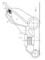
- Fig. 1 is a side elevation of a rotary lawnmower mounting one form of grass catcher;
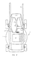
- Fig. 2 is a plan view thereof;
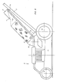
- Fig. 3 is a side elevation of the same lawnmower mounting a different form of grass catcher;
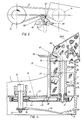
- Fig. 4 is a fragmentary sectional view of the compacting means employed; and
- Fig. 5 is a fragmentary plan view of the auger selective drive.
- With reference to Figs. 1, 2 and 3, it will be noted that a
rotary lawnmower 6 consists of abaseplate 7 rendered mobile bywheels 8 and under the control of ahandle 9. An internal combustion, or electric,motor 10 is centrally mounted upon thebaseplate 7 and agrass catcher 11A (of solid form) or 11B (of flexible form) is supported in position between the arms of thehandle 9 with itsentry portion 12 overlying thebaseplate 7. Thegrass catcher 11A may be provided with acarrying handle 13. Thegrass catcher 11A is preferably formed of thermoplastic material and of permanent shape, and in use is removed from thebaseplate 7 and returned thereto after disposal of its contents of grass cuttings. In the case of the grass catcher 11B, shown in Fig. 3, it is preferably formed of flexible material, such as polythene and in the form of a sock or tube closed at its outer end 14. The flexible bag type grass catcher 11 B is supported within a channelledmember 15 mounted at its opposite ends byleg members 16 between the arms of thehandle 9. The flexible container 11 B progressively assumes a solid form throughout its length as filling thereof progresses. - Preferably the
baseplate 7 is of convoluted form as represented by the fragmentary view of Fig. 4. Agrass discharge opening 17 is provided at the end of the convolution in thebaseplate 7. Themotor 10 has a vertical downwardly extendingdrive shaft 18 journalled near its lower end in abearing 19 and terminating in agrass cutting assembly 20, composed of either one or more cutter bars, or a cutting disc mounting pivotable cutting blades. A cutter bar is shown provided with acutting portion 21 at its outer end provided with a notched impacting, trailingflange 22. Short of itsouter end 23 theshaft 18 carries apulley 24. - It will be noted that a vertically mounted
auger conveyor 25 has its outertubular housing 26 integrally formed with aplatform 27 which may be provided in the casing of thebaseplate 7. Theplatform 27 is positioned below the upper surface of thebaseplate 7 which is provided with an opening through which the conveyor housing 26 protrudes. Anauger screw 28, rotatable within thehousing 26 is mounted upon anaxial shaft 29 journalled in abearing 30 and terminating at its lower end in apulley wheel 31. A V-belt 32 is reeved over the twopulleys shaft 18 to theaugur 28. Thebelt 32 andpulleys air compartment 43 by a partition 44. Thus, when theauger 28 is rotated in a clockwise direction as viewed in Fig. 4, grass cuttings exiting through thedischarge opening 17 will be carried by the blades of theauger 28 through theopen top 33 of thehousing 26 for discharge into agrass catcher 11A or 11B. - Restriction to the passage of
grass cuttings 34 may be provided within theauger conveyor 25, for example by providing aconverging housing 26 towards itsupper end 33. Preferably, however, such restriction is provided by a restrictingelbow 35 which may be incorporated on thebaseplate 7 or on thegrass catcher 11A, of Fig. 2, or may be a separable unit attachable to the flexible grass catcher 11B, of Fig. 3. Compaction of thegrass cuttings 34 occurs due to an internal angular passage 35A provided within theelbow 35. Additionally, the internal passage 35A may be constricted in cross-section either at a single location or throughout. Preferably, cross-sectional constriction occurs progressively along the passage. In eitherevent grass cuttings 34 can be compacted to approximately 1/12th their normal volume through being forced by theauger 28 through theelbow 35. It has been found that having once been compacted thegrass cuttings 34 remain substantially in that condition even when discharged into either thecatcher 11A or 11 B. Thus, it will be seen that thecatcher 11A or 11B is not itself subjected to excessive internal pressure under normal conditions as compression of the grass occurs before entry to the catcher. Due to their greatly reduced volume thegrass cuttings 34 may be more readily disposed of as refuse. In the case of the catcher 11 B, it is feasible that such a sock filled with compacted grass cuttings may be discarded, together with its contents, into a garbage tin. - It is preferred that drive to the
auger screw 28 be removed when agrass catcher 11A or 11B is removed from thebaseplate 7. To this end, alever handle 36, to be manipulated by an operator or automatically upon removal of the catcher, is fixed upon avertical shaft 37 which carries aroller 38 at its lower end engageable with the V-belt 32 in order to control the tension therein (see Figs. 4 and 5). Thelever 36 is in the position shown in heavy outline in Fig. 5 when theelbow 35 is in position over theend 33 of theauger housing 26 and is locked in that position by apawl 39 carried on theelbow 36 which latches the extension lug 40 on theshaft 37. Therefore, when theelbow 35 is withdrawn thelever 36 andshaft 37 are free to rotate to the chain dotted position shown in Fig. 5 where theroller 38 ceases to exert tension on the V-belt 32 so that drive from themotor shaft 18 is disconnected from theauger shaft 29. - As a refinement there may be provided a pressure indicator 41 (Fig. 1) which is pivoted to the
catcher 11 A to protrude progressively therefrom as internal pressure increases as the catcher becomes fully loaded. A redcoloured area 42 may be exposed to the operator's view when emptying of the catcher is required.
Claims (8)
Applications Claiming Priority (2)
| Application Number | Priority Date | Filing Date | Title |
|---|---|---|---|
| AU8404/83 | 1983-03-11 | ||
| AUPF840483 | 1983-03-11 |
Publications (3)
| Publication Number | Publication Date |
|---|---|
| EP0137814A1 EP0137814A1 (en) | 1985-04-24 |
| EP0137814A4 EP0137814A4 (en) | 1985-07-01 |
| EP0137814B1 true EP0137814B1 (en) | 1988-01-13 |
Family
ID=3770030
Family Applications (1)
| Application Number | Title | Priority Date | Filing Date |
|---|---|---|---|
| EP84900951A Expired EP0137814B1 (en) | 1983-03-11 | 1984-03-06 | Rotary lawnmower |
Country Status (5)
| Country | Link |
|---|---|
| EP (1) | EP0137814B1 (en) |
| JP (1) | JPS60500798A (en) |
| NZ (1) | NZ207436A (en) |
| WO (1) | WO1984003413A1 (en) |
| ZA (1) | ZA841826B (en) |
Families Citing this family (9)
| Publication number | Priority date | Publication date | Assignee | Title |
|---|---|---|---|---|
| DE3814119A1 (en) * | 1988-04-27 | 1989-11-09 | Sabo Maschf | COLLECTING OR COLLECTING DEVICE WITH LEVEL INDICATOR FOR A GARDEN, LAWN OR LANDSCAPE MAINTENANCE DEVICE |
| US4986062A (en) * | 1990-01-18 | 1991-01-22 | White Consolidated Industries, Inc. | Bagger attachment for grass mowers |
| JP3037794B2 (en) * | 1991-09-25 | 2000-05-08 | 本田技研工業株式会社 | Glass harvester full detection device for reapers |
| EP0759268A1 (en) * | 1995-08-11 | 1997-02-26 | Alfred Dr. Eggenmüller | Method and device for collecting and compacting plant matter |
| GB9920756D0 (en) * | 1999-09-02 | 1999-11-03 | Bosch Gmbh Robert | Grass collection systems for lawnmowers |
| GB2354419A (en) * | 1999-09-22 | 2001-03-28 | Ingemar Bjurenvall | Method of and apparatus for crop production |
| ITMO20090148A1 (en) * | 2009-05-29 | 2010-11-30 | R C M S P A | MACHINE FOR SPINDLE COLLECTION |
| CN108901316A (en) * | 2018-07-12 | 2018-11-30 | 芜湖慧宇商贸有限公司 | A kind of grass trimmer |
| SE546143C2 (en) * | 2022-03-23 | 2024-06-11 | Husqvarna Ab | Compact collection bag storage |
Family Cites Families (5)
| Publication number | Priority date | Publication date | Assignee | Title |
|---|---|---|---|---|
| US3222853A (en) * | 1964-03-30 | 1965-12-14 | Henry F Michael | Grass and leaf baler for rotary lawn mowers |
| US3664097A (en) * | 1970-12-17 | 1972-05-23 | Richard A Pedigo | Grass-clippings pelletizer for lawnmowers |
| US3846963A (en) * | 1972-10-04 | 1974-11-12 | R Pedigo | Grass clipping compacter attachment for lawnmowers |
| FR2235639A1 (en) * | 1973-07-06 | 1975-01-31 | Bernard Moteurs | Rotary type lawn mower with clippings compactor - clippings collect against spring loaded flap until spring is overcome |
| SE423778B (en) * | 1980-10-06 | 1982-06-07 | Ulf Bertil Reinhall | DEVICE FOR Mower and similar |
-
1984
- 1984-03-06 WO PCT/AU1984/000035 patent/WO1984003413A1/en not_active Ceased
- 1984-03-06 JP JP59501707A patent/JPS60500798A/en active Pending
- 1984-03-06 EP EP84900951A patent/EP0137814B1/en not_active Expired
- 1984-03-08 NZ NZ207436A patent/NZ207436A/en unknown
- 1984-03-12 ZA ZA841826A patent/ZA841826B/en unknown
Also Published As
| Publication number | Publication date |
|---|---|
| ZA841826B (en) | 1984-10-31 |
| NZ207436A (en) | 1986-08-08 |
| EP0137814A1 (en) | 1985-04-24 |
| EP0137814A4 (en) | 1985-07-01 |
| WO1984003413A1 (en) | 1984-09-13 |
| JPS60500798A (en) | 1985-05-30 |
Similar Documents
| Publication | Publication Date | Title |
|---|---|---|
| US3736736A (en) | Baling attachment for lawn mowers | |
| US3222853A (en) | Grass and leaf baler for rotary lawn mowers | |
| CA2979636C (en) | Shredding and baling apparatus and method | |
| US4443997A (en) | Apparatus for vacuum collection and compacting of leaves and grass clippings | |
| US6341470B1 (en) | Wrapping machine | |
| US4095705A (en) | Agricultural airplane loading device | |
| US4986063A (en) | Method and apparatus for compacting grass, leafage or similar material | |
| DE69224223T2 (en) | Garbage collection device | |
| EP0069739A1 (en) | Device in lawn mowers, leaf-collecting machines and the like | |
| US4057952A (en) | Rotary mower and shredder device | |
| US4986062A (en) | Bagger attachment for grass mowers | |
| US10721872B2 (en) | Baling apparatus and method | |
| US5584762A (en) | Apparatus and method for compacting cotton materials in a basket | |
| WO1984003413A1 (en) | Rotary lawnmower | |
| CA1124527A (en) | Method for collecting mowed lawn and apparatus for effecting the same | |
| US4306408A (en) | Grass catcher assembly | |
| US3002332A (en) | Grass catcher and guard for lawn mowers | |
| AU560605B2 (en) | Improved rotary lawnmower | |
| US5730047A (en) | Portable refuse compacting container | |
| US4592469A (en) | Storage cartridge for plastic sheet tubing | |
| EP1352554B1 (en) | A combined compacting and wrapping machine | |
| US3754500A (en) | Lawn debris chopper and compactor | |
| US3469380A (en) | Machines for cutting grass or other vegetable matter | |
| KR102899999B1 (en) | Pet bottle automatic compactor | |
| US2971313A (en) | Grass catching basket for use on rotary lawn mower |
Legal Events
| Date | Code | Title | Description |
|---|---|---|---|
| PUAI | Public reference made under article 153(3) epc to a published international application that has entered the european phase |
Free format text: ORIGINAL CODE: 0009012 |
|
| AK | Designated contracting states |
Designated state(s): DE FR GB |
|
| 17P | Request for examination filed |
Effective date: 19850304 |
|
| 17Q | First examination report despatched |
Effective date: 19860807 |
|
| GRAA | (expected) grant |
Free format text: ORIGINAL CODE: 0009210 |
|
| AK | Designated contracting states |
Kind code of ref document: B1 Designated state(s): DE FR GB |
|
| REF | Corresponds to: |
Ref document number: 3468612 Country of ref document: DE Date of ref document: 19880218 |
|
| ET | Fr: translation filed | ||
| PLBE | No opposition filed within time limit |
Free format text: ORIGINAL CODE: 0009261 |
|
| STAA | Information on the status of an ep patent application or granted ep patent |
Free format text: STATUS: NO OPPOSITION FILED WITHIN TIME LIMIT |
|
| 26N | No opposition filed | ||
| PG25 | Lapsed in a contracting state [announced via postgrant information from national office to epo] |
Ref country code: GB Effective date: 19890306 |
|
| GBPC | Gb: european patent ceased through non-payment of renewal fee | ||
| PG25 | Lapsed in a contracting state [announced via postgrant information from national office to epo] |
Ref country code: FR Free format text: LAPSE BECAUSE OF NON-PAYMENT OF DUE FEES Effective date: 19891130 |
|
| PG25 | Lapsed in a contracting state [announced via postgrant information from national office to epo] |
Ref country code: DE Effective date: 19891201 |
|
| REG | Reference to a national code |
Ref country code: FR Ref legal event code: ST |