EP0137610A1 - Dispositif de commande - Google Patents
Dispositif de commande Download PDFInfo
- Publication number
- EP0137610A1 EP0137610A1 EP84305265A EP84305265A EP0137610A1 EP 0137610 A1 EP0137610 A1 EP 0137610A1 EP 84305265 A EP84305265 A EP 84305265A EP 84305265 A EP84305265 A EP 84305265A EP 0137610 A1 EP0137610 A1 EP 0137610A1
- Authority
- EP
- European Patent Office
- Prior art keywords
- control
- motor
- screw
- ball
- lead
- Prior art date
- Legal status (The legal status is an assumption and is not a legal conclusion. Google has not performed a legal analysis and makes no representation as to the accuracy of the status listed.)
- Granted
Links
- 230000033001 locomotion Effects 0.000 claims abstract description 20
- 230000003134 recirculating effect Effects 0.000 claims description 5
- 230000008878 coupling Effects 0.000 description 2
- 238000010168 coupling process Methods 0.000 description 2
- 238000005859 coupling reaction Methods 0.000 description 2
- 230000000694 effects Effects 0.000 description 2
- 230000009347 mechanical transmission Effects 0.000 description 1
- 238000000034 method Methods 0.000 description 1
- 230000002441 reversible effect Effects 0.000 description 1
- 230000011664 signaling Effects 0.000 description 1
- 238000004804 winding Methods 0.000 description 1
Images

Classifications
-
- B—PERFORMING OPERATIONS; TRANSPORTING
- B64—AIRCRAFT; AVIATION; COSMONAUTICS
- B64C—AEROPLANES; HELICOPTERS
- B64C13/00—Control systems or transmitting systems for actuating flying-control surfaces, lift-increasing flaps, air brakes, or spoilers
- B64C13/24—Transmitting means
- B64C13/26—Transmitting means without power amplification or where power amplification is irrelevant
- B64C13/28—Transmitting means without power amplification or where power amplification is irrelevant mechanical
- B64C13/345—Transmitting means without power amplification or where power amplification is irrelevant mechanical with artificial feel
-
- B—PERFORMING OPERATIONS; TRANSPORTING
- B64—AIRCRAFT; AVIATION; COSMONAUTICS
- B64C—AEROPLANES; HELICOPTERS
- B64C13/00—Control systems or transmitting systems for actuating flying-control surfaces, lift-increasing flaps, air brakes, or spoilers
- B64C13/24—Transmitting means
- B64C13/26—Transmitting means without power amplification or where power amplification is irrelevant
- B64C13/28—Transmitting means without power amplification or where power amplification is irrelevant mechanical
- B64C13/34—Transmitting means without power amplification or where power amplification is irrelevant mechanical using toothed gearing
-
- B—PERFORMING OPERATIONS; TRANSPORTING
- B64—AIRCRAFT; AVIATION; COSMONAUTICS
- B64C—AEROPLANES; HELICOPTERS
- B64C13/00—Control systems or transmitting systems for actuating flying-control surfaces, lift-increasing flaps, air brakes, or spoilers
- B64C13/24—Transmitting means
- B64C13/38—Transmitting means with power amplification
- B64C13/50—Transmitting means with power amplification using electrical energy
- B64C13/507—Transmitting means with power amplification using electrical energy with artificial feel
-
- B—PERFORMING OPERATIONS; TRANSPORTING
- B64—AIRCRAFT; AVIATION; COSMONAUTICS
- B64D—EQUIPMENT FOR FITTING IN OR TO AIRCRAFT; FLIGHT SUITS; PARACHUTES; ARRANGEMENTS OR MOUNTING OF POWER PLANTS OR PROPULSION TRANSMISSIONS IN AIRCRAFT
- B64D31/00—Power plant control; Arrangement thereof
- B64D31/02—Initiating means
- B64D31/04—Initiating means actuated personally
-
- F—MECHANICAL ENGINEERING; LIGHTING; HEATING; WEAPONS; BLASTING
- F16—ENGINEERING ELEMENTS AND UNITS; GENERAL MEASURES FOR PRODUCING AND MAINTAINING EFFECTIVE FUNCTIONING OF MACHINES OR INSTALLATIONS; THERMAL INSULATION IN GENERAL
- F16H—GEARING
- F16H25/00—Gearings comprising primarily only cams, cam-followers and screw-and-nut mechanisms
- F16H25/18—Gearings comprising primarily only cams, cam-followers and screw-and-nut mechanisms for conveying or interconverting oscillating or reciprocating motions
- F16H25/20—Screw mechanisms
- F16H25/22—Screw mechanisms with balls, rollers, or similar members between the co-operating parts; Elements essential to the use of such members
-
- G—PHYSICS
- G05—CONTROLLING; REGULATING
- G05G—CONTROL DEVICES OR SYSTEMS INSOFAR AS CHARACTERISED BY MECHANICAL FEATURES ONLY
- G05G7/00—Manually-actuated control mechanisms provided with one single controlling member co-operating with one single controlled member; Details thereof
- G05G7/02—Manually-actuated control mechanisms provided with one single controlling member co-operating with one single controlled member; Details thereof characterised by special provisions for conveying or converting motion, or for acting at a distance
-
- Y—GENERAL TAGGING OF NEW TECHNOLOGICAL DEVELOPMENTS; GENERAL TAGGING OF CROSS-SECTIONAL TECHNOLOGIES SPANNING OVER SEVERAL SECTIONS OF THE IPC; TECHNICAL SUBJECTS COVERED BY FORMER USPC CROSS-REFERENCE ART COLLECTIONS [XRACs] AND DIGESTS
- Y10—TECHNICAL SUBJECTS COVERED BY FORMER USPC
- Y10T—TECHNICAL SUBJECTS COVERED BY FORMER US CLASSIFICATION
- Y10T74/00—Machine element or mechanism
- Y10T74/18—Mechanical movements
- Y10T74/18568—Reciprocating or oscillating to or from alternating rotary
- Y10T74/18576—Reciprocating or oscillating to or from alternating rotary including screw and nut
- Y10T74/18712—Contamination related
- Y10T74/1872—Imperforate enclosure
-
- Y—GENERAL TAGGING OF NEW TECHNOLOGICAL DEVELOPMENTS; GENERAL TAGGING OF CROSS-SECTIONAL TECHNOLOGIES SPANNING OVER SEVERAL SECTIONS OF THE IPC; TECHNICAL SUBJECTS COVERED BY FORMER USPC CROSS-REFERENCE ART COLLECTIONS [XRACs] AND DIGESTS
- Y10—TECHNICAL SUBJECTS COVERED BY FORMER USPC
- Y10T—TECHNICAL SUBJECTS COVERED BY FORMER US CLASSIFICATION
- Y10T74/00—Machine element or mechanism
- Y10T74/19—Gearing
- Y10T74/19642—Directly cooperating gears
- Y10T74/19698—Spiral
- Y10T74/19702—Screw and nut
- Y10T74/19744—Rolling element engaging thread
- Y10T74/19781—Non-recirculating rolling elements
Definitions
- control apparatus for example an aircraft thrust demand unit or 'throttle-box', wherein a manually movable operating member or lever is operable to be moved to effect a control action, for example via a position encoder and suitable control signal link, or via a mechanical coupling, and wherein the operating member is associated with an electric motor of which the member may form a part and which is preferably a rotary or linear stepper motor, the arrangement being such that, while the motor may be energised to move the operating member and hence provide an automatic control mode of the apparatus, the motor is nevertheless overridable manually without disengaging or declutching the motor.
- the motor may be operable to provide a measure of resistance or 'feel' to manual movement of the member and/or to introduce a more marked resistance to such movement through certain detent positions within the overall range of movement.
- control apparatus for enabling an operator to control associated apparatus to which, in use, the control apparatus is connected, for example a thrust demand unit for enabling a pilot to control the engine of an aircraft
- the apparatus comprising a fixed support member, a movable control member supported by the support member, output means coupled to the control memeber and operable for transmitting to said associated apparatus control signals indicative of the position of the control member relative to the support member, an electrical stepper motor coupled to the control member, and motor energisation means connected to said motor and operable for driving said motor to produce movement of the control member and/or for energising said motor to produce a resistance against manual movement of the control member
- the apparatus comprises a recirculating ball-screw assembly including a lead-screw (3,22,31,43) and a ball-nut (4,23,33,42) engaged upon the lead-screw, one of the said lead-screw and ball-nut being coupled to said control member (2,24,34
- control apparatus for enabling an operator to control associated apparatus to which, in use, the control apparatus is connected, for example a thrust demand unit for enabling a pilot to control the engine of an aircraft
- the apparatus comprising a fixed support member, a movable control member supported by the support member, output means coupled to the control member and operable for transmitting to said associated apparatus'control signals indicative of the position of the control member relative to the support member, an electrical stepper motor coupled to the control member, and motor energisation means connected to said motor and operable for driving said motor to produce movement of the control member and/or for energising said motor to produce a resistance against manual movement of the control member
- the control apparatus is constructed as a retrofit unit for being incorporated into an existing control system which system includes said associated apparatus and a manually movable control device coupled to control the apparatus, the movable control member of the control apparatus comprising connection means (26,36,46,59) for being mechanically coupled to said control device of the existing control system
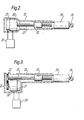
- Figure 1 shows an aircraft throttle-box comprising a rectangular enclosure 1 with a slotted top from which protrudes a handle 2.
- a ball-screw and rotary stepper motor assembly including a fixed helically grooved shaft 3 on which there is mounted a co-acting recirculating ball-nut 4.
- the nut of a ball-screw comprises a cage holding a series of balls 11 which are engaged in the groove of the shaft 3 and which are guided by the cage along a continuous or recirculating path.
- a ball-screw acts in just the same way as an ordinary threaded lead-screw and nut - the balls together act like the thread of the ordinary nut to transmit motion between the nut and the screw-shaft but because the balls are able to roll within the shaft-groove, the ball-screw may have a very low coefficient of friction such that, for a much finer thread pitch than the case with an ordinary lead-screw assembly, the ball screw is reversible in the sense that, if the nut thereof is pushed along the shaft, it will move either by rotating itself around the shaft or by rotating the shaft.
- the ball-nut 4 is fixed within, or is formed as an integral part of, the rotor 5 of an electrical stepper motor 10 which also comprises a stator 6.
- the stator is supported with respect to the rotor by thrust transmissive bearings 7.
- the inner end of the handle 2 is fixed to the stator 6.
- the motor windings are connected to an electronic motor drive and control output unit 8.
- the throttle-box also includes any suitable means for signalling to unit 8 the position along shaft 3 of the movable part of the ball-screw and motor assembly. This can be by use of any suitable ones of the encoding methods and devices described in our UK patent No. 2,073,887B and our UK patent application No. 2,114,717A, or by any other suitable device.
- a rotary or linear position encoder 9 could be provided as part of the ball-nut and motor assembly.
- the handle 2 is. moved back and forth along the shaft 3 carrying with it the motor and ball-nut, the ball-nut and motor rotor rotating with respect to the motor stator to permit this rotary movement.
- the movement is translated to a control signal acting on the engine throttle(s) either electrically by- way of the position encoder 9 -and unit 8, or any suitable kind of mechanical output could be provided, for example a simple Bowden cable arrangement coupled to the motor.
- the motor can be energised during such manual operation to give a predetermined 'feel' resistance to the movement and/or to generate marked detents at certain positions just as described in the aforementioned patent and patent application.
- the motor In auto-throttle mode, the motor is powered to a level sufficient to produce rotation of the rotor and ball-nut and hence driven movement of the motor and handle 2 along the shaft 3.
- the motor force can be overcome by the pilot if he wishes without having to disconnect or de-clutch the motor.
- the handle 2 could be replaced by a lever of which one end protrudes from enclosure 1, the other end is pivotably connected to the enclosure at a point below the shaft 3 and motor, and which is pivotably coupled at an intermediate point to the motor stator. This gives a quadrant movement of the protruding portion of the lever but the operation is otherwise the same as for the illustrated embodiment.
- the apparatus shown could be used for other applications, as well as for aircraft throttle control, either on-board an aircraft to control say wing sweep or the like, or elsewhere, for example to control valves, and like equipment in the factory say.
- apparatus could be in the form of an actuator unit which can be incorporated in or added to some existing manual control device to give that device a servo or automatic operating capability if it does not already have one or simply so as to provide for electrically generated 'feel' resistance and/or detents to the manual movement.
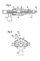
- Figures 2, 3, 4 and 5 illustrate respective actuator units which could be incorporated into the design of aircraft auto-throttle-boxes or retro-fitted to an existing manual throttle-box.
- an assembly of a rotary stepper motor 20 and rotary position encoder 26 is fitted in one end of a cylindrical housing 21, the motor shaft 22 being formed as the lead-screw of a recirculating ball-screw which also comprises a ball-nut 23.
- the nut 23 is fixed to one end of a hollow, elongate actuator output member 24 which is able to slide within, and the other end of which protrudes from, housing 21, this other end being adapted (for example by comprising an eyelet 26 as shown) for coupling to the handle of a throttle-box either locally or elsewhere in the mechanical transmission between the handle and engine throttle.
- the motor and encoder are coupled to an electronic motor drive and interface unit 25.
- the figure 3 actuator comprises an output member 34 with an eyelet 36, a ball-screw shaft 31 and ball-nut 33 arranged in a housing 35 in a manner similar to that shown in figure 2 except that, in figure 3, the assembly of a motor 30 and encoder 37 is mounted below the ball-screw shaft 31 and is coupled thereto by gears 32.
- the motor 40, position encoder 41 and ball-nut 42 form an integral assembly like that in figure 1.
- the ball-screw shaft 43 is able to move linearly, with respect to a housing 45, but not rotate, while the motor stator is fixed with respect to the housing 45. Rotation of the motor rotor and ball-nut thus move the shaft 43 and the attached actuator output member 44 with its eyelet 46 linearly.
- the actuator output member 50 has an eyelet 59 at one end and its other end connected to a shaft 51 which also supports a gear wheel 52 in engagement with respective further gear wheels 53 and 54 on the shafts of a rotary stepper motor 55 and a position encoder 56, both of which are connected to an electronics unit 57 as before.
- the actuator output member 50 has a quadrant movement as shown by arrows 58.
Applications Claiming Priority (2)
| Application Number | Priority Date | Filing Date | Title |
|---|---|---|---|
| GB838321376A GB8321376D0 (en) | 1983-08-09 | 1983-08-09 | Control apparatus |
| GB8321376 | 1983-08-09 |
Publications (2)
| Publication Number | Publication Date |
|---|---|
| EP0137610A1 true EP0137610A1 (fr) | 1985-04-17 |
| EP0137610B1 EP0137610B1 (fr) | 1988-10-12 |
Family
ID=10547009
Family Applications (1)
| Application Number | Title | Priority Date | Filing Date |
|---|---|---|---|
| EP84305265A Expired EP0137610B1 (fr) | 1983-08-09 | 1984-08-02 | Dispositif de commande |
Country Status (7)
| Country | Link |
|---|---|
| US (1) | US4947070A (fr) |
| EP (1) | EP0137610B1 (fr) |
| JP (1) | JPS6062623A (fr) |
| CA (1) | CA1259294A (fr) |
| DE (1) | DE3474534D1 (fr) |
| ES (1) | ES8604460A1 (fr) |
| GB (1) | GB8321376D0 (fr) |
Cited By (5)
| Publication number | Priority date | Publication date | Assignee | Title |
|---|---|---|---|---|
| US5029778A (en) * | 1989-09-11 | 1991-07-09 | The Boeing Company | Throttle control system having real-time-computed thrust vs throttle position function |
| GB2308880A (en) * | 1996-01-04 | 1997-07-09 | Daimler Benz Ag | Controlling the speed of a motor vehicle |
| KR20180080184A (ko) * | 2015-11-04 | 2018-07-11 | 제프리 에스.엠. 헤드릭 | 항공기 오토스로틀 또는 오토파일럿 시스템을 위한 정밀 조작기 |
| DE102012108635B4 (de) * | 2012-09-14 | 2019-12-24 | Voestalpine Signaling Sainerholz Gmbh | Vorrichtung zum Umstellen von Zungenschienen einer Weiche |
| US10737799B2 (en) | 2015-11-04 | 2020-08-11 | Geoffrey S. M. Hedrick | Precision operator for an aircraft autothrottle or autopilot system with engine performance adjust |
Families Citing this family (25)
| Publication number | Priority date | Publication date | Assignee | Title |
|---|---|---|---|---|
| JPS63168233U (fr) * | 1987-03-30 | 1988-11-01 | ||
| GB8919453D0 (en) * | 1989-08-26 | 1990-05-30 | British Aerospace | Control apparatus |
| NL9001394A (nl) * | 1990-06-19 | 1992-01-16 | P G Van De Veen Consultancy B | Bestuurbare demper. |
| DE4112350A1 (de) * | 1991-04-16 | 1992-01-02 | Erwin Palige | Kugelrollspindellaeufer-motor |
| US5182505A (en) * | 1991-06-19 | 1993-01-26 | Honeywell Inc. | Aircraft control surface position transducer |
| JPH06170676A (ja) * | 1992-12-04 | 1994-06-21 | Toshiba Mach Co Ltd | 工作機械の軸回転駆動装置 |
| FR2708112B1 (fr) * | 1993-07-22 | 1995-09-01 | Ratier Figeac Soc | Dispositif de commande à manche de pilotage, notamment mini-manche asservi pour aéronef. |
| US5637940A (en) * | 1994-04-05 | 1997-06-10 | Smc Kabushiki Kaisha | Electric Actuator |
| US5744884A (en) * | 1995-10-17 | 1998-04-28 | Applied Precision, Inc. | Liner motion micropositioning apparatus and method |
| DE19634336A1 (de) * | 1996-08-24 | 1998-02-26 | Walter Edel | Anordnung und Verfahren zum Vermessen von Kreissägeblättern |
| FR2806951B1 (fr) * | 2000-03-31 | 2002-06-14 | Aro | Dispositif de motorisation electrique pour pince d'outillage |
| DE10144146A1 (de) * | 2001-09-07 | 2003-04-03 | Wittenstein Ag | Steuerknüppel |
| DE10310717A1 (de) * | 2003-03-10 | 2004-09-23 | Wittenstein Ag | Vorrichtung zum Steuern eines Fahrzeuges |
| DE502004000621D1 (de) * | 2004-02-07 | 2006-06-29 | Festo Ag & Co | Elektrischer Linearantrieb mit einer Steckkupplung zwischen einem Spindeltrieb und einem Motormodul |
| US20060066269A1 (en) * | 2004-04-27 | 2006-03-30 | Bae Systems Pic | Control apparatus |
| US20070235594A1 (en) * | 2006-04-06 | 2007-10-11 | Honeywell International, Inc. | Pilot flight control stick feedback system |
| DE102007046583A1 (de) * | 2007-09-27 | 2009-04-16 | Eads Deutschland Gmbh | Motorischer Spindelantrieb |
| US9570956B2 (en) | 2011-03-16 | 2017-02-14 | Shalom Levin | Planetary, push-pull electromagnetic motor |
| FR3005130B1 (fr) * | 2013-04-24 | 2015-04-17 | Sonceboz Sa | Actionneur electrique a tige filetee |
| US10570770B2 (en) * | 2013-12-11 | 2020-02-25 | United Technologies Corporation | Variable vane positioning apparatus for a gas turbine engine |
| FR3068733B1 (fr) * | 2017-07-05 | 2019-08-09 | Fly By Wire Systems France | Systeme de commande de gaz d'un aeronef |
| US11479364B2 (en) | 2017-12-13 | 2022-10-25 | Safe Flight Instrument, Llc | Aircraft torque control device |
| WO2020081615A1 (fr) * | 2018-10-15 | 2020-04-23 | Safe Flight Instrument Corporation | Dispositif de commande de couple d'aéronef |
| CN110821685B (zh) * | 2019-09-26 | 2022-04-12 | 安徽延达智能科技有限公司 | 一种汽油机油门自动化控制机构 |
| US11548654B2 (en) | 2020-10-05 | 2023-01-10 | Honeywell International Inc. | Piston engine powered aircraft actuation system |
Citations (5)
| Publication number | Priority date | Publication date | Assignee | Title |
|---|---|---|---|---|
| US2446393A (en) * | 1945-06-14 | 1948-08-03 | Eaton Mfg Co | Screw-threaded mechanical movement |
| US2772841A (en) * | 1955-04-28 | 1956-12-04 | North American Aviation Inc | Aircraft trim control |
| US3156132A (en) * | 1961-05-24 | 1964-11-10 | Jr Henry Peter Borie | Remote control mechanical actuator |
| US3161074A (en) * | 1962-02-14 | 1964-12-15 | Korthaus Helmut | Electromotive adjusting device |
| GB2073887A (en) * | 1980-03-15 | 1981-10-21 | British Aerospace | Aircraft thrust controller |
Family Cites Families (9)
| Publication number | Priority date | Publication date | Assignee | Title |
|---|---|---|---|---|
| NL290775A (fr) * | 1963-03-27 | 1965-07-25 | Philips Nv | |
| DE1261936B (de) * | 1963-06-11 | 1968-02-29 | Bodenseewerk Perkin Elmer Co | Steuerknueppel, insbesondere fuer Flugzeugsteuerungen |
| US3331972A (en) * | 1964-04-15 | 1967-07-18 | Bodenseewerk Perkin Elmer Co | Magnetic control stick system |
| NL7003056A (fr) * | 1970-03-04 | 1971-09-07 | ||
| US3660704A (en) * | 1970-07-31 | 1972-05-02 | Thomas O Paine | Ball-screw linear actuator |
| JPS4735123U (fr) * | 1971-05-08 | 1972-12-19 | ||
| US4110649A (en) * | 1976-11-22 | 1978-08-29 | Electric Vehicle Corporation Of America | Variable speed DC motor |
| US4438662A (en) * | 1981-04-02 | 1984-03-27 | Walton Eric K | Automatic control system having manual control engageable at will |
| GB2114717B (en) * | 1982-01-22 | 1986-03-12 | British Aerospace | Control apparatus |
-
1983
- 1983-08-09 GB GB838321376A patent/GB8321376D0/en active Pending
-
1984
- 1984-08-02 EP EP84305265A patent/EP0137610B1/fr not_active Expired
- 1984-08-02 DE DE8484305265T patent/DE3474534D1/de not_active Expired
- 1984-08-08 ES ES534965A patent/ES8604460A1/es not_active Expired
- 1984-08-08 CA CA000460527A patent/CA1259294A/fr not_active Expired
- 1984-08-09 JP JP59165776A patent/JPS6062623A/ja active Pending
-
1988
- 1988-06-24 US US07/212,082 patent/US4947070A/en not_active Expired - Fee Related
Patent Citations (5)
| Publication number | Priority date | Publication date | Assignee | Title |
|---|---|---|---|---|
| US2446393A (en) * | 1945-06-14 | 1948-08-03 | Eaton Mfg Co | Screw-threaded mechanical movement |
| US2772841A (en) * | 1955-04-28 | 1956-12-04 | North American Aviation Inc | Aircraft trim control |
| US3156132A (en) * | 1961-05-24 | 1964-11-10 | Jr Henry Peter Borie | Remote control mechanical actuator |
| US3161074A (en) * | 1962-02-14 | 1964-12-15 | Korthaus Helmut | Electromotive adjusting device |
| GB2073887A (en) * | 1980-03-15 | 1981-10-21 | British Aerospace | Aircraft thrust controller |
Cited By (12)
| Publication number | Priority date | Publication date | Assignee | Title |
|---|---|---|---|---|
| US5029778A (en) * | 1989-09-11 | 1991-07-09 | The Boeing Company | Throttle control system having real-time-computed thrust vs throttle position function |
| GB2308880A (en) * | 1996-01-04 | 1997-07-09 | Daimler Benz Ag | Controlling the speed of a motor vehicle |
| GB2308880B (en) * | 1996-01-04 | 1998-12-09 | Daimler Benz Ag | Operating-element arrangement for controlling the longitudinal speed of a motor vehicle |
| DE102012108635B4 (de) * | 2012-09-14 | 2019-12-24 | Voestalpine Signaling Sainerholz Gmbh | Vorrichtung zum Umstellen von Zungenschienen einer Weiche |
| KR20180080184A (ko) * | 2015-11-04 | 2018-07-11 | 제프리 에스.엠. 헤드릭 | 항공기 오토스로틀 또는 오토파일럿 시스템을 위한 정밀 조작기 |
| EP3250458A4 (fr) * | 2015-11-04 | 2018-08-22 | Geoffrey S.M. Hedrick | Opérateur de précision pour système d'automanette ou d'autopilote d'aéronef |
| US10099795B2 (en) | 2015-11-04 | 2018-10-16 | Innovative Solutions & Support, Inc. | Precision operator for an aircraft autothrottle or autopilot system |
| US10633105B2 (en) | 2015-11-04 | 2020-04-28 | Geoffrey S. M. Hedrick | Precision operator for an aircraft autothrottle or autopilot system with engine performance adjust |
| US10737799B2 (en) | 2015-11-04 | 2020-08-11 | Geoffrey S. M. Hedrick | Precision operator for an aircraft autothrottle or autopilot system with engine performance adjust |
| EP3792183A1 (fr) * | 2015-11-04 | 2021-03-17 | Geoffrey S.M. Hedrick | Opérateur de précision pour système d'automanette ou d'autopilote d'aéronef |
| US10974839B2 (en) | 2015-11-04 | 2021-04-13 | Geoffrey S. M. Hedrick | Precision operator for an aircraft autothrottle or autopilot system with engine performance adjust |
| US11027854B2 (en) | 2015-11-04 | 2021-06-08 | Geoffrey S. M. Hedrick | Precision operator for an aircraft autothrottle or autopilot system with engine performance adjust |
Also Published As
| Publication number | Publication date |
|---|---|
| ES534965A0 (es) | 1986-02-01 |
| US4947070A (en) | 1990-08-07 |
| GB8321376D0 (en) | 1983-09-28 |
| EP0137610B1 (fr) | 1988-10-12 |
| DE3474534D1 (en) | 1988-11-17 |
| ES8604460A1 (es) | 1986-02-01 |
| JPS6062623A (ja) | 1985-04-10 |
| CA1259294A (fr) | 1989-09-12 |
Similar Documents
| Publication | Publication Date | Title |
|---|---|---|
| EP0137610A1 (fr) | Dispositif de commande | |
| US5253604A (en) | Electro-mechanical steering device, especially for boats | |
| EP0085518B1 (fr) | Appareil de commande | |
| US4516063A (en) | Control apparatus | |
| EP1718885B1 (fr) | Organe d'entrainement lineaire avec un embrayage de surcharge | |
| JP3574820B2 (ja) | 差動式リニヤ・アクチュエータ | |
| DE69627506T3 (de) | Luftströmungssteuervorrichtung | |
| EP2359028B1 (fr) | Systèmes de transmission à sorties multiples | |
| EP0101579A2 (fr) | Direction | |
| GB2114717A (en) | Control apparatus | |
| KR850001892B1 (ko) | 공작기계의 슬라이드 위치 자동 결정장치 | |
| GB2141203A (en) | Electromechanical linear actuator | |
| US4719816A (en) | Device for positioning an actuator | |
| EP1091470B1 (fr) | Dispositif déconnecteur automatique | |
| US5634373A (en) | Rotational to linear movement actuator with limiter | |
| EP0105588A1 (fr) | Actionneur pour transmission commandé électriquement | |
| EP0366691B1 (fr) | Servo-direction a cremaillere, en particulier pour vehicules a moteur | |
| US20210371083A1 (en) | Aircraft torque control device | |
| EP0265738B1 (fr) | Appareil de commande | |
| EP0045635A2 (fr) | Dispositif de positionnement électrique télécommandé | |
| US4094226A (en) | Hydraulic control apparatus with feedback | |
| US6647814B2 (en) | Selective drive mechanism | |
| US5466996A (en) | Electromechanical remote-control device | |
| GB2148460A (en) | Control apparatus | |
| EP0415467B1 (fr) | Dispositif de commande |
Legal Events
| Date | Code | Title | Description |
|---|---|---|---|
| PUAI | Public reference made under article 153(3) epc to a published international application that has entered the european phase |
Free format text: ORIGINAL CODE: 0009012 |
|
| AK | Designated contracting states |
Designated state(s): DE FR GB IT NL SE |
|
| 17P | Request for examination filed |
Effective date: 19850531 |
|
| 17Q | First examination report despatched |
Effective date: 19860507 |
|
| D17Q | First examination report despatched (deleted) | ||
| RAP1 | Party data changed (applicant data changed or rights of an application transferred) |
Owner name: BRITISH AEROSPACE PUBLIC LIMITED COMPANY |
|
| ITF | It: translation for a ep patent filed |
Owner name: BARZANO' E ZANARDO ROMA S.P.A. |
|
| GRAA | (expected) grant |
Free format text: ORIGINAL CODE: 0009210 |
|
| AK | Designated contracting states |
Kind code of ref document: B1 Designated state(s): DE FR GB IT NL SE |
|
| REF | Corresponds to: |
Ref document number: 3474534 Country of ref document: DE Date of ref document: 19881117 |
|
| ET | Fr: translation filed | ||
| PLBE | No opposition filed within time limit |
Free format text: ORIGINAL CODE: 0009261 |
|
| STAA | Information on the status of an ep patent application or granted ep patent |
Free format text: STATUS: NO OPPOSITION FILED WITHIN TIME LIMIT |
|
| 26N | No opposition filed | ||
| ITTA | It: last paid annual fee | ||
| PGFP | Annual fee paid to national office [announced via postgrant information from national office to epo] |
Ref country code: SE Payment date: 19920831 Year of fee payment: 9 Ref country code: NL Payment date: 19920831 Year of fee payment: 9 Ref country code: FR Payment date: 19920831 Year of fee payment: 9 |
|
| PGFP | Annual fee paid to national office [announced via postgrant information from national office to epo] |
Ref country code: GB Payment date: 19921016 Year of fee payment: 9 |
|
| PGFP | Annual fee paid to national office [announced via postgrant information from national office to epo] |
Ref country code: DE Payment date: 19921102 Year of fee payment: 9 |
|
| PG25 | Lapsed in a contracting state [announced via postgrant information from national office to epo] |
Ref country code: GB Effective date: 19930802 |
|
| PG25 | Lapsed in a contracting state [announced via postgrant information from national office to epo] |
Ref country code: SE Effective date: 19930803 |
|
| PG25 | Lapsed in a contracting state [announced via postgrant information from national office to epo] |
Ref country code: NL Effective date: 19940301 |
|
| GBPC | Gb: european patent ceased through non-payment of renewal fee |
Effective date: 19930802 |
|
| NLV4 | Nl: lapsed or anulled due to non-payment of the annual fee | ||
| PG25 | Lapsed in a contracting state [announced via postgrant information from national office to epo] |
Ref country code: FR Effective date: 19940429 |
|
| PG25 | Lapsed in a contracting state [announced via postgrant information from national office to epo] |
Ref country code: DE Effective date: 19940503 |
|
| REG | Reference to a national code |
Ref country code: FR Ref legal event code: ST |
|
| EUG | Se: european patent has lapsed |
Ref document number: 84305265.5 Effective date: 19940310 |