EP0137552B1 - Stepped polygon scan mirror - Google Patents
Stepped polygon scan mirror Download PDFInfo
- Publication number
- EP0137552B1 EP0137552B1 EP84201329A EP84201329A EP0137552B1 EP 0137552 B1 EP0137552 B1 EP 0137552B1 EP 84201329 A EP84201329 A EP 84201329A EP 84201329 A EP84201329 A EP 84201329A EP 0137552 B1 EP0137552 B1 EP 0137552B1
- Authority
- EP
- European Patent Office
- Prior art keywords
- mirror
- target
- face
- axis
- assembly
- Prior art date
- Legal status (The legal status is an assumption and is not a legal conclusion. Google has not performed a legal analysis and makes no representation as to the accuracy of the status listed.)
- Expired
Links
Images

Classifications
-
- G—PHYSICS
- G02—OPTICS
- G02B—OPTICAL ELEMENTS, SYSTEMS OR APPARATUS
- G02B26/00—Optical devices or arrangements for the control of light using movable or deformable optical elements
- G02B26/08—Optical devices or arrangements for the control of light using movable or deformable optical elements for controlling the direction of light
- G02B26/10—Scanning systems
- G02B26/12—Scanning systems using multifaceted mirrors
-
- G—PHYSICS
- G02—OPTICS
- G02B—OPTICAL ELEMENTS, SYSTEMS OR APPARATUS
- G02B5/00—Optical elements other than lenses
- G02B5/08—Mirrors
- G02B5/09—Multifaceted or polygonal mirrors, e.g. polygonal scanning mirrors; Fresnel mirrors
Definitions
- a significant problem with the known polygonal scanners is that they generally are operated at very high rates of rotation, for example (39,375 or 78,750) revolutions per minute. This high speed operation generates high windage losses and creates severe acoustical noise unless the mirror is operated in a partially or completely evacuated chamber. Such operation is difficult and expensive to implement.
- each mirror face in the mirror assembly comprises a plurality of planar mirror segments, the mirror segments being arranged to form a stepped structure in which each mirror segment in a given mirror face is parallel to each other mirror segment in the mirror face, and in that the mirror segments in a given mirror face do not all lie in one and the same plane.
- Each mirror face 20 comprises a plurality of planar mirror segments or planar submirrors 22.
- Each submirror has a geometric center.
- the centers of each submirror in a mirror face lie substantially on an arc of a circle.
Landscapes
- Physics & Mathematics (AREA)
- General Physics & Mathematics (AREA)
- Optics & Photonics (AREA)
- Mechanical Optical Scanning Systems (AREA)
- Facsimile Scanning Arrangements (AREA)
- Radiation Pyrometers (AREA)
- Photometry And Measurement Of Optical Pulse Characteristics (AREA)
Description
- The invention relates to mirror assemblies for scanning radiation onto a target. The invention also relates to imaging and other systems using such mirror assemblies.
- Such mirror assemblies may be used in thermal imaging systems. In many known thermal imaging systems, radiation from a scene to be imaged is scanned onto either a single detector or a detector array by means of one or more scanners. One known scanner is a polygonal scan mirror, such as mentioned in U.S. Patent Specification No. 36.14.193.
- A significant problem with the known polygonal scanners is that they generally are operated at very high rates of rotation, for example (39,375 or 78,750) revolutions per minute. This high speed operation generates high windage losses and creates severe acoustical noise unless the mirror is operated in a partially or completely evacuated chamber. Such operation is difficult and expensive to implement.
- It is an object of the invention to provide a rotary scan mirror which can be operated at high speeds with reduced windage losses.
- The mirror assembly according to the invention is characterized in that each mirror face in the mirror assembly comprises a plurality of planar mirror segments, the mirror segments being arranged to form a stepped structure in which each mirror segment in a given mirror face is parallel to each other mirror segment in the mirror face, and in that the mirror segments in a given mirror face do not all lie in one and the same plane.
- In a preferred embodiment of the mirror assembly, the axis of the cylindrical mirror arrangement is an n-fold axis of rotational symmetry.
- It is also preferable that a cross-section through each mirror face, in a plane which is perpendicular to the axis of the mirror arrangement, approximates an arc of a circle. Moreover, each mirror face preferably has a reflection plane of symmetry, where the symmetry plane lies in the middle of the mirror face.
- In one embodiment of the invention the cylindrical mirror arrangement has six mirror faces.
- A system for scanning radiation onto a target according to the invention comprising a housing, having an aperture through which incoming radiation can pass into the housing, a target in the housing and a mirror assembly in the housing for scanning the incoming radiation onto the target, is characterized in that the mirror assembly is shaped as defined hereinbefore.
- In one version of the scanningsystem the target comprises an array of infrared detectors.
- The invention will now be described with reference to the accompanying drawing, wherein:
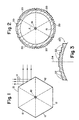
- Figure 1 is a schematic diagram of a cross-section through a known polygon scan mirror.
- Figure 2 is a cross-sectional view through a scan mirror assembly according to the invention.
- Figure 3 is a cross-sectional view through a single mirror face of a scan mirror according to the invention.
- Figure 4 is a schematic diagram of a system according to the invention for scanning radiation onto a target.
- A known polygonal scan mirror is shown in Figure 1, which schematically shows a cross-section through the scan mirror perpendicular to the
axis 10 thereof. The scan mirror of Figure 1 has sixmirror faces 12. Eachmirror face 12 has a planar surface so that all light which is incident at a given angle of incidence is reflected in a single angle of reflection (for a given position of the scan mirror). Moreover, eachmirror face 12 subtends an angle α with respect toaxis 10. - In the operation of the known scan mirror,
radiation 14 which is incident on amirror face 12 is reflected onto a detector, array, or some other target (not shown in Figure 1). As the scan mirror is rotated aroundaxis 10, successive bundles of parallel rays (each bundle having a different angular orientation) are reflected onto the target. After the scan mirror rotates through an angle of α, the next mirror face 12 functions to reflect the radiation bundles onto the target. In this way, the target is scanned six times for each complete rotation of the scan mirror of Figure 1. When such a polygonal scanner is operated at very high rates of rotation high windage losses are generated and severe acoustical noises are created. - Figure 2 shows a cross-section through a scan mirror assembly according to the present invention which does not have those disadvantages. The scan mirror assembly includes a
circular cylinder 16 which is preferably hollow and lightweight, for ease of rotation.Cylinder 16 may be made of, for example, aluminum. Along the axis ofcircular cylinder 16, ashaft 18 is provided.Shaft 18 may be fixed on the axis ofcylinder 16 by way of top and bottom plates (not shown) covering the ends ofcylinder 16. - Provided on the outer surface of
cylinder 16 are a number ofmirror faces 20. In Figure 2, there are sixmirror faces 20 arranged around the cylinder axis on the surface ofcylinder 16. Preferably, each mirror face subtends the same angle (shown as α in Figure 2) with respect to the cylinder axis. In fact, each mirror face is preferably constructed substantially identically to each other mirror face, so that the axis of the cylindrical mirror arrangement of Figure 2 is a 6-fold axis of rotational symmetry. In this preferred embodiment, the axis of the cylindrical mirror arrangement is most generally an n-fold axis of rotational symmetry, where n is the number of mirror faces and where n is an integer greater than or equal to two. (The axis of the cylindrical mirror arrangement is n-fold if rotation of the mirror arrangement through an angle of 2π/n results in an orientation of the mirror arrangement which is indistinguishable from the original orientation). - A more detailed view of a single mirror face according to the invention is shown in Figure 3.
Mirror face 20 comprises a plurality ofplanar mirror segments 22. Themirror segments 22 are arranged to form a stepped structure in which eachmirror segment 22 is parallel to eachother mirror segment 22 in thesame mirror face 20. In Figure 3, the plane of eachmirror face 22 extends perpendicularly into and out of the plane of the drawing. In this cross-section which is in a plane perpendicular to the axis of the cylindrical mirror arrangement, it can be seen that the cross-section through the mirror arrangement approximates an arc of a circle. - As described above, it is preferred that each cylindrical mirror arrangement according to the invention has an axis of rotational symmetry. In addition, each mirror face 20 preferably has a reflection plane of symmetry. As shown in Figure 3, this
symmetry plane 24 lies in the middle of themirror face 20. - Each
mirror face 20 comprises a plurality of planar mirror segments orplanar submirrors 22. Each submirror has a geometric center. Preferably, the centers of each submirror in a mirror face lie substantially on an arc of a circle. - A scan mirror assembly according to the invention can be made, for example, in the following manner. A female mold is provided having an inner surface which is accurately shaped to match the desired stepped structure of at least one mirror face. This inner surface is treated with a release compound, and is then covered with a thin reflective metal film (such as aluminum or silver). The reflective film may be applied, for example, by electroplating or by sputtering. After the reflective film is applied to the inner surface of the mold, the cylinder (
element 16 in Figure 2) is placed near the film, and the space between the cylinder and the film is filled with epoxy to bond the two together. This entire process is then repeated for each mirror face. - Alternatively, each mirror face could be made by photoetching a substrate using a series of masks so as to produce the desired stepped structure. The etched product could be provided with a reflective film by sputtering or by electroplating, and the entire mirror face could then be bonded to the cylinder (which might be a polygonal cylinder).
- A system for scanning radiation onto a target is schematically shown in Figure 4. The system includes a
housing 26, atarget 28, and amirror assembly 30. Both thetarget 28 and themirror assembly 30 are located within thehousing 26.Housing 26 is provided with anaperture 32 through whichincoming radiation 34 can pass into the housing. - The
target 28 in thehousing 26 is preferably an infrared detector or an array of such detectors. In the case of a linear array, the array extends perpendicularly into and out of the plane of the drawing. Thetarget 28 is fixed to thehousing 26, as schematically shown at 36. - The
mirror assembly 30 of the system shown in Figure 4 is preferably the scan mirror assembly shown in cross-section in Figure 2. For simplicity, only onemirror face 20 is shown in Figure 4. However, it is to be understood that themirror assembly 30 in Figure 4 has mirror faces 20 completely surrounding the axis, as shown in Figure 2. - In addition to target 28 and
mirror assembly 30, the system according to the invention for scanning radiation onto the target further includes alens 38 arranged between thetarget 28 and themirror assembly 30. The target 28 (e.g. the array of infrared detectors) is arranged in the focal plane of thelens 38. - The system according to the invention for scanning radiation onto a target operates in the following manner.
Incoming radiation 34, as well as other bundles of parallel rays which intersect the rays shown, pass through theaperture 32 and into thehousing 26. These rays are incident on the surfaces of the mirror segments or submirrors of amirror face 20 of themirror assembly 30. Depending upon the angular orientation of themirror face 20, a given bundle or bundles of parallel rays will be reflected throughlens 38 and focused on to thetarget 28. As themirror assembly 30 is rotated (by means which are not shown) in the direction of the arrow aroundaxis 40, the angular orientation of themirror face 20 is changed to reflect a different bundle or bundles of parallel rays throughlens 38 and onto the target. In this manner, radiation emanating from a scene is scanned onto one or more radiation detectors. - After the
mirror assembly 30 is rotated through a given angle (the angle α , as shown in Figure 2), the next succeedingmirror face 20 is positioned to reflect the incoming radiation throughlens 38 and onto thetarget 28. Thus, for each complete rotation of themirror assembly 30 around theaxis 40, the scene is scanned onto thetarget 28 six times (or, in general, once for each mirror face 20 of the mirror assembly 30). - In practice, it is usually necessary to rotate the
mirror assembly 30 at a speed of 39,375 or 78,750 revolutions per minute. In prior systems operating at these speeds, it was necessary to rotate the mirror assembly in a partial vacuum. According to the present invention, however, the stepped polygon scan mirror should be capable of operating at these speeds in a normal atmosphere without undue windage losses, and without excessive acoustical noise.
Claims (7)
- A mirror assembly for scanning radiation onto a target comprising
a cylindrical mirror (16; 30) arrangement having n mirror faces (20) arranged around an axis (18; 40), n being an integer greater than or equal to two;
characterized in that each mirror face (20) comprises a plurality of planar mirror segments (22), the mirror segments being arranged to form a stepped structure in which each mirror segment (22) in a given mirror face (20) is parallel to each other mirror segment in the said mirror face, and in that the mirror segments (22) in a given mirror face (20) do not all lie in one and the same plane. - A mirror assembly as claimed in Claim 1, characterized in that the axis (18; 40) of the cylindrical mirror arrangement (16; 30) is an n-fold axis of rotational symmetry.
- A mirror assembly as claimed in Claim 2, characterized in that a cross-section through each mirror face (20), in a plane which is perpendicular to the axis (18; 40) of the mirror arrangement, approximates an arc of a circle.
- A mirror assembly as claimed in Claim 3, characterized in that each mirror face (20) has a reflection plane of symmetry, where the symmetry plane (24) lies in the middle of the mirror face (20).
- A mirror assembly as claimed in Claim 4, characterized in that the cylindrical mirror arrangement has six mirror faces (20).
- A system for scanning radiation onto a target, said system comprising:
a housing (26) having an aperture (32) through which incoming radiation (34) can pass into the housing;
a target (28) in the housing; and
a mirror assembly (30) according to any of Claims 1-5, in the housing, for scanning the incoming radiation onto the target. - A system as claimed in Claim 6, characterized in that the target (28) comprises an array of infrared detectors.
Applications Claiming Priority (2)
| Application Number | Priority Date | Filing Date | Title |
|---|---|---|---|
| US06/535,478 US4518218A (en) | 1983-09-26 | 1983-09-26 | Stepped polygon scan mirror |
| US535478 | 1983-09-26 |
Publications (3)
| Publication Number | Publication Date |
|---|---|
| EP0137552A2 EP0137552A2 (en) | 1985-04-17 |
| EP0137552A3 EP0137552A3 (en) | 1987-09-02 |
| EP0137552B1 true EP0137552B1 (en) | 1991-07-03 |
Family
ID=24134420
Family Applications (1)
| Application Number | Title | Priority Date | Filing Date |
|---|---|---|---|
| EP84201329A Expired EP0137552B1 (en) | 1983-09-26 | 1984-09-14 | Stepped polygon scan mirror |
Country Status (4)
| Country | Link |
|---|---|
| US (1) | US4518218A (en) |
| EP (1) | EP0137552B1 (en) |
| JP (1) | JPS6095512A (en) |
| DE (1) | DE3484763D1 (en) |
Families Citing this family (11)
| Publication number | Priority date | Publication date | Assignee | Title |
|---|---|---|---|---|
| US4889418A (en) * | 1986-03-31 | 1989-12-26 | Hughes Aircraft Company | Rotating cylindrical beam splitter |
| AT395571B (en) * | 1986-10-17 | 1993-01-25 | Voest Alpine Eisenbahnsysteme | DEVICE FOR DETECTING THE SPATIAL ORIENTATION OF INADWALLY WARMED POINTS OF WHEEL BEARINGS AND / OR WHEEL RUNNINGS OF RAIL VEHICLES |
| JPH02273712A (en) * | 1989-04-14 | 1990-11-08 | Hitachi Koki Co Ltd | Rotary polygon mirror |
| US5223700A (en) * | 1989-07-07 | 1993-06-29 | Sumitomo Electric Industries, Inc. | Bar code reader having a polygon mirror providing different scan line lengths |
| JPH0486723A (en) * | 1990-07-31 | 1992-03-19 | Toshiba Corp | Polyhedral mirror and production thereof |
| KR100224612B1 (en) * | 1996-12-27 | 1999-10-15 | 윤종용 | Laser scanning unit |
| US6542304B2 (en) | 1999-05-17 | 2003-04-01 | Toolz, Ltd. | Laser beam device with apertured reflective element |
| RU2158948C1 (en) * | 2000-04-24 | 2000-11-10 | Государственное унитарное предприятие Научно-технический производственный комплекс "Геофизика-Арт" | Optical scanner |
| US7057326B2 (en) * | 2003-05-29 | 2006-06-06 | General Electric Company | Rotor body containment shell with reduced windage losses |
| US10122847B2 (en) * | 2014-07-20 | 2018-11-06 | Google Technology Holdings LLC | Electronic device and method for detecting presence and motion |
| DE102016108234A1 (en) * | 2016-05-03 | 2017-11-09 | Pch Innovations Gmbh | A light-reflecting object and method for providing such an object |
Family Cites Families (5)
| Publication number | Priority date | Publication date | Assignee | Title |
|---|---|---|---|---|
| US3488102A (en) * | 1966-03-25 | 1970-01-06 | Technical Operations Inc | Laser beam scanning apparatus |
| US3614193A (en) * | 1970-04-15 | 1971-10-19 | Columbia Broadcasting Systems | Light scanning system utilizing diffraction optics |
| GB1484006A (en) * | 1973-08-06 | 1977-08-24 | Hawker Siddeley Dynamics Ltd | Optical scanning systems |
| GB1510460A (en) * | 1974-06-10 | 1978-05-10 | Hawker Siddeley Dynamics Ltd | Optical scanning systems |
| US3944323A (en) * | 1974-12-23 | 1976-03-16 | Xerox Corporation | Variable spot size scanning system |
-
1983
- 1983-09-26 US US06/535,478 patent/US4518218A/en not_active Expired - Fee Related
-
1984
- 1984-09-14 DE DE8484201329T patent/DE3484763D1/en not_active Expired - Lifetime
- 1984-09-14 EP EP84201329A patent/EP0137552B1/en not_active Expired
- 1984-09-25 JP JP59198770A patent/JPS6095512A/en active Granted
Also Published As
| Publication number | Publication date |
|---|---|
| US4518218A (en) | 1985-05-21 |
| EP0137552A2 (en) | 1985-04-17 |
| DE3484763D1 (en) | 1991-08-08 |
| EP0137552A3 (en) | 1987-09-02 |
| JPH0376726B2 (en) | 1991-12-06 |
| JPS6095512A (en) | 1985-05-28 |
Similar Documents
| Publication | Publication Date | Title |
|---|---|---|
| US4518218A (en) | Stepped polygon scan mirror | |
| US4923263A (en) | Rotating mirror optical scanning device | |
| EP0816891B1 (en) | Integrated panoramic and high resolution sensor optics | |
| EP0484801A2 (en) | Optical system for partitioning a real image | |
| US4413878A (en) | Imaging systems | |
| JP3478566B2 (en) | X-ray CT scanner | |
| US6791101B2 (en) | Scanning apparatus | |
| GB1569879A (en) | Radiation scanning system | |
| AU652695B2 (en) | An imager | |
| US5075553A (en) | IR sensor for a scanned staggered element linear array having improved cold shielding | |
| US4461534A (en) | Optical scanning system with two sequential reflection stations | |
| GB2115143A (en) | Infra-red radiation detector assembly | |
| US3956586A (en) | Method of optical scanning | |
| US5046794A (en) | Hologon scanner system | |
| EP1145065A2 (en) | Ultra-wide field of view concentric scanning sensor system | |
| US5724171A (en) | Optical scanning apparatus | |
| GB2135789A (en) | Optical scanner | |
| US5977536A (en) | All-around observation device having a rotatable objective element | |
| US3885857A (en) | Convergent beam scanner with multiple mirror defocus compensation | |
| EP0655129B1 (en) | Rotating flexible filter spectrometer | |
| JPS59224810A (en) | Optical image former | |
| US5721614A (en) | Optoelectronic camera with anti-reflective coating having a continuously variable thickness and method of making same | |
| GB2091440A (en) | Scan mirrors and mechanically scanned imaging systems | |
| JP2837466B2 (en) | Rotating polygon mirror manufacturing method | |
| SU1739347A1 (en) | Optical scanning system |
Legal Events
| Date | Code | Title | Description |
|---|---|---|---|
| PUAI | Public reference made under article 153(3) epc to a published international application that has entered the european phase |
Free format text: ORIGINAL CODE: 0009012 |
|
| AK | Designated contracting states |
Designated state(s): DE FR GB NL SE |
|
| PUAL | Search report despatched |
Free format text: ORIGINAL CODE: 0009013 |
|
| AK | Designated contracting states |
Kind code of ref document: A3 Designated state(s): DE FR GB NL SE |
|
| 17P | Request for examination filed |
Effective date: 19880301 |
|
| 17Q | First examination report despatched |
Effective date: 19900305 |
|
| GRAA | (expected) grant |
Free format text: ORIGINAL CODE: 0009210 |
|
| AK | Designated contracting states |
Kind code of ref document: B1 Designated state(s): DE FR GB NL SE |
|
| REF | Corresponds to: |
Ref document number: 3484763 Country of ref document: DE Date of ref document: 19910808 |
|
| ET | Fr: translation filed | ||
| PLBE | No opposition filed within time limit |
Free format text: ORIGINAL CODE: 0009261 |
|
| STAA | Information on the status of an ep patent application or granted ep patent |
Free format text: STATUS: NO OPPOSITION FILED WITHIN TIME LIMIT |
|
| 26N | No opposition filed | ||
| PGFP | Annual fee paid to national office [announced via postgrant information from national office to epo] |
Ref country code: GB Payment date: 19920828 Year of fee payment: 9 |
|
| PGFP | Annual fee paid to national office [announced via postgrant information from national office to epo] |
Ref country code: FR Payment date: 19920923 Year of fee payment: 9 |
|
| PGFP | Annual fee paid to national office [announced via postgrant information from national office to epo] |
Ref country code: SE Payment date: 19920928 Year of fee payment: 9 |
|
| PGFP | Annual fee paid to national office [announced via postgrant information from national office to epo] |
Ref country code: NL Payment date: 19920930 Year of fee payment: 9 |
|
| PGFP | Annual fee paid to national office [announced via postgrant information from national office to epo] |
Ref country code: DE Payment date: 19921125 Year of fee payment: 9 |
|
| PG25 | Lapsed in a contracting state [announced via postgrant information from national office to epo] |
Ref country code: GB Effective date: 19930914 |
|
| PG25 | Lapsed in a contracting state [announced via postgrant information from national office to epo] |
Ref country code: SE Effective date: 19930915 |
|
| PG25 | Lapsed in a contracting state [announced via postgrant information from national office to epo] |
Ref country code: NL Effective date: 19940401 |
|
| GBPC | Gb: european patent ceased through non-payment of renewal fee |
Effective date: 19930914 |
|
| NLV4 | Nl: lapsed or anulled due to non-payment of the annual fee | ||
| PG25 | Lapsed in a contracting state [announced via postgrant information from national office to epo] |
Ref country code: FR Free format text: LAPSE BECAUSE OF NON-PAYMENT OF DUE FEES Effective date: 19940531 |
|
| PG25 | Lapsed in a contracting state [announced via postgrant information from national office to epo] |
Ref country code: DE Effective date: 19940601 |
|
| REG | Reference to a national code |
Ref country code: FR Ref legal event code: ST |
|
| EUG | Se: european patent has lapsed |
Ref document number: 84201329.4 Effective date: 19940410 |