EP0137352A2 - Plastic tamper-proof closure - Google Patents
Plastic tamper-proof closure Download PDFInfo
- Publication number
- EP0137352A2 EP0137352A2 EP84111027A EP84111027A EP0137352A2 EP 0137352 A2 EP0137352 A2 EP 0137352A2 EP 84111027 A EP84111027 A EP 84111027A EP 84111027 A EP84111027 A EP 84111027A EP 0137352 A2 EP0137352 A2 EP 0137352A2
- Authority
- EP
- European Patent Office
- Prior art keywords
- tear
- overcap
- elements
- tamper
- screw cap
- Prior art date
- Legal status (The legal status is an assumption and is not a legal conclusion. Google has not performed a legal analysis and makes no representation as to the accuracy of the status listed.)
- Withdrawn
Links
Images

Classifications
-
- B—PERFORMING OPERATIONS; TRANSPORTING
- B65—CONVEYING; PACKING; STORING; HANDLING THIN OR FILAMENTARY MATERIAL
- B65D—CONTAINERS FOR STORAGE OR TRANSPORT OF ARTICLES OR MATERIALS, e.g. BAGS, BARRELS, BOTTLES, BOXES, CANS, CARTONS, CRATES, DRUMS, JARS, TANKS, HOPPERS, FORWARDING CONTAINERS; ACCESSORIES, CLOSURES, OR FITTINGS THEREFOR; PACKAGING ELEMENTS; PACKAGES
- B65D50/00—Closures with means for discouraging unauthorised opening or removal thereof, with or without indicating means, e.g. child-proof closures
- B65D50/02—Closures with means for discouraging unauthorised opening or removal thereof, with or without indicating means, e.g. child-proof closures openable or removable by the combination of plural actions
- B65D50/04—Closures with means for discouraging unauthorised opening or removal thereof, with or without indicating means, e.g. child-proof closures openable or removable by the combination of plural actions requiring the combination of simultaneous actions, e.g. depressing and turning, lifting and turning, maintaining a part and turning another one
- B65D50/041—Closures with means for discouraging unauthorised opening or removal thereof, with or without indicating means, e.g. child-proof closures openable or removable by the combination of plural actions requiring the combination of simultaneous actions, e.g. depressing and turning, lifting and turning, maintaining a part and turning another one the closure comprising nested inner and outer caps or an inner cap and an outer coaxial annular member, which can be brought into engagement to enable removal by rotation
-
- B—PERFORMING OPERATIONS; TRANSPORTING
- B65—CONVEYING; PACKING; STORING; HANDLING THIN OR FILAMENTARY MATERIAL
- B65D—CONTAINERS FOR STORAGE OR TRANSPORT OF ARTICLES OR MATERIALS, e.g. BAGS, BARRELS, BOTTLES, BOXES, CANS, CARTONS, CRATES, DRUMS, JARS, TANKS, HOPPERS, FORWARDING CONTAINERS; ACCESSORIES, CLOSURES, OR FITTINGS THEREFOR; PACKAGING ELEMENTS; PACKAGES
- B65D41/00—Caps, e.g. crown caps or crown seals, i.e. members having parts arranged for engagement with the external periphery of a neck or wall defining a pouring opening or discharge aperture; Protective cap-like covers for closure members, e.g. decorative covers of metal foil or paper
- B65D41/32—Caps or cap-like covers with lines of weakness, tearing-strips, tags, or like opening or removal devices, e.g. to facilitate formation of pouring openings
- B65D41/34—Threaded or like caps or cap-like covers provided with tamper elements formed in, or attached to, the closure skirt
- B65D41/3442—Threaded or like caps or cap-like covers provided with tamper elements formed in, or attached to, the closure skirt with rigid bead or projections formed on the tamper element and coacting with bead or projections on the container
- B65D41/3447—Threaded or like caps or cap-like covers provided with tamper elements formed in, or attached to, the closure skirt with rigid bead or projections formed on the tamper element and coacting with bead or projections on the container the tamper element being integrally connected to the closure by means of bridges
Definitions
- the invention relates to a tamper-evident closure with the features mentioned in the preamble of claim 1.
- the condition of the closure should show whether it was opened after the first closure or not.
- Tamper-evident closures made of sheet metal are known, in which a closure cap has a smooth, cylindrical jacket which is flanged over the thread of a mouth and under the retaining bead.
- the present invention is intended to design a tamper-evident closure made of plastic in such a way that it can be attached to threaded mouths with a retaining bead using normal closing machines.
- the closure should be able to be closed and opened as often as desired after opening for the first time, destroying its originality markings.
- the overcap is held captive on the screw cap. It is freely movable axially a certain distance, so that the projections or projections and recesses, which are necessary for the transmission of a torque from the overcap to the screw cap, can snap in and out.
- Such a closure can easily be screwed onto bottles by hand or by capping machines.
- the projections or projections and depressions lie against each other so that the screw cap is carried by the overcap.
- the tear-off elements are detached and thereby make it clearly recognizable that the closure has been opened. Since the user has to exert an axial force against the mouth and the container when the screw cap is first opened to take the screw cap with him, he must also press the tear-off elements against the mouth with the aid of the edge section of the overcap, so that its claws under the retaining bead of the mouth stay anchored. Since the screw cap now moves upwards relative to the mouth, the tear-off elements, which are stuck under the retaining bead of the mouth, must necessarily be torn off.
- top and bottom refer to the position of a closure z. B. on an upright bottle.
- the screw cap with the tear-off elements can be produced in one piece by injection molding.
- the tear-off elements including claws can be easily removed from the mold after injection molding and that when the closure is first applied to a mouth, tear-off webs which hold the tear-off elements remain undamaged.
- the tear-off elements can be connected to one another by easily tearable connecting webs for better grip when demolding after injection molding and when the mouth is closed for the first time.
- Different embodiments allow different methods of attaching the closure to a mouth for the first time.
- a closure designed according to claim 10 can be bounced after the threaded cap has been screwed on, as a result of which the tear-off elements come into their position required for tamper-evident securing, in which the claws engage behind the retaining bead of the mouth.
- this bouncing can be replaced by a screwing operation.
- an internal thread is provided on the overcap and an associated external thread is provided on the screw cap.
- the tamper-evident closure can also be used as a child-resistant closure.
- Some of the protrusions or depressions have sloping surfaces. When unscrewing these inclined surfaces have the effect that an overcap which is only slightly pressed against the screw cap performs a ratchet movement, so that a tight screw cap is not taken along. The screw cap can only be taken along if a considerable axial force is exerted that a small child cannot exert.
- FIGS. 6 to 9 show a second embodiment with an overcap to be screwed on.
- the screw cap 1 has an internal thread 3 for the threaded mouth 2 of a bottle.
- Six approximately radially directed, rib-shaped projections 7 are provided on the end face 5 of the screw cap.
- Similar projections 18 are present on the inner end face of the overcap 14.
- the projections have mutually parallel flanks 9 and 20, which lie in axial or axially parallel planes.
- the overcap 14 has a relatively large annular groove 23 above its edge, while the screw cap has an annular bead 26 on its outside, which is arranged at some distance from the open end of the screw cap. After the screw cap has been impacted onto the overcap, the annular bead 26 can move axially within the annular groove 23. The screw cap is thus held captive within the overcap with axial play. In one extreme position, the projections 7 of the screw cap touch the end face 16 of the overcap, in the other extreme position the annular bead 26 abuts a shoulder 28 on the lower edge of the annular groove 23.
- Threaded mouths 2 on containers or bottles which are suitable for receiving a screw cap with tamper-evident protection have a retaining bead 32 (FIG. 4), generally just below an external thread 34.
- Tear-off elements 36 which are held on the edge of the screw cap 1 by tear-off webs 38, serve to ensure tamper evidence.
- four tear-off elements 36 are provided, and each is held by three tear-off webs 38.
- the tear-off elements 36 are connected to one another by connecting webs 40 connected.
- the tear-off elements 36 are parts of a hollow cone surface with a central angle of approximately 30 °. Except for the connecting webs 40, they are separated from one another by V-shaped cutouts 42. The opening angle of each section is also approx. 30 °.
- a claw 44 in the form of an annular rib is provided on the inner wall of each of the tear-off elements.
- each tear-off element On the outer wall, namely at the lower edge, each tear-off element has an annular flange 46. As FIG. 5 shows, this annular flange, which projects under the edge of the overcap after the first closure, shows that the closure has not yet been opened.
- each tear-off element 36 has two outer ribs 48, which run approximately parallel to the generatrix of the tapered surface of the tear-off elements.
- the screw cap is produced together with the tear-off elements in the position shown in FIGS. 2 and 3 by injection molding.
- the screw cap is first turned, for example by a capping machine, onto the mouth of the bottle, the tear-off elements 36 and their claws 44 easily gripping over the external thread 34 and the holding bead 32 of the mouth.
- the overcap 14 is chipped in the axial direction over the screw cap 1, so that the situation according to FIG. 5 then results, in which the annular bead 26 of the screw cap 1 engages in the annular groove 23 of the overcap 14.
- the overcap is thus held captive on the screw cap.
- the edge section 29 of the overcap has pressed the tear-off elements 36 inwards, so that their claws 44 engage behind, ie under the retaining bead 32 of the mouth.
- the V-shaped cutouts 42 between the tear-offs elements have narrowed into a slit.
- the lower edges 50 of the tear-off elements now form arches while they were in a radial plane in the production state.
- the closure can be screwed even more tightly, the projections 18 of the overcap taking the projections 7 of the screw cap with them.
- the overcap For the first unscrewing, the overcap must be pressed against the screw cap so that the projections 18 of the overcap can take the projections 7 and with them the screw cap in the direction of rotation.
- the edge section 29 inevitably holds the tear-off elements 36 inward and thus the claws 44 firmly below the holding bead 32 of the mouth, so that the tear-off elements 36 cannot move upward.
- the tear-off webs 38 must be torn through. The tear-off elements 36 are thus separated from the inner cap 1, whereby it can be seen that the closure has been opened.
- the second exemplary embodiment, shown in FIGS. 6 to 9, differs from the first in that the overcap 14 can be screwed onto the screw cap 1.
- a multiple-thread, here three-thread, external thread 60 is provided on the outer wall of the screw cap, near its lower edge, and a corresponding internal thread 62 is provided on the overcap 14 at the lower edge of its edge portion 29.
- the cap has 16 projections 64 with flanks 66 and 68 on its inner end face. While the flanks 66 lie in axially parallel or axial planes, the flanks 68 have an inclination with respect to the end face 16 which is between 30 and 60 °, in particular approximately 45 ° is. This results in a child lock, which is described below.
- the overcap 14 is screwed onto the inner cap 1 in a position according to FIG.
- the tear-off elements 36 stand out unhindered, as in FIGS. 7 and 8.
- the screwing of the overcap onto the screw cap is first ended by the beginnings of the external thread 60 of the screw cap 1 abutting the ends of the internal thread 62 of the overcap. If the closure is turned onto the mouth 2 in this way, the torque that can be transmitted between the two caps is sufficient to screw the screw cap 1 onto the external thread 34 of the mouth. If rotation is then continued with increased torque and / or the overcap is bounced open, the edge section 29 widens and slides over the external thread 60 until it comes into the annular groove 23. As a result, both closure parts are in turn held captive.
- the projections 64 and 7 now engage one behind the other in the direction of rotation. If necessary, the closure can now be screwed tight.
- the edge section 29 presses the tear-off elements 36 inward, so that the claws 44 engage under the retaining bead 32 of the mouth.
- the edge section 29 in turn holds the tear-off elements 36 against the mouth during the unscrewing process and the claws 44 firmly below the retaining bead 32 of the mouth, so that the tear-off webs 38 have to be torn through.
Abstract
Ein Originalitätsverschluß aus Kunststoff für Gewindemündungen mit Haltewulst an Behältern, insbesondere Flaschen. Der Verschluß hat eine Schraubkappe, an der mit axialem Spiel eine Überkappe gehaltert ist. An beiden sind Vorsprünge angeordnet, die innerhalb des axialen Spiels ein- und ausgerückt werden können und als Mitnehmer wirken. Zur Originalitätssicherung ist die Schraubkappe mit Abreißelementen versehen, die mit Krallen unter den Haltewulst greifen. Bei geschlossener Mündung werden die Krallen von der Überkappe in dieser Lage gehalten. Beim erstmaligen Öffnen werden die Abreißelemente zwangsläufig abgerissen. Zur zusätzlichen Ausgstaltung als Kindersicherung wird eine Gruppe von vorsprüngen so ausgestaltet, daß sie beim Zuschrauben immer als Mitnehmer fungieren, beim Abschrauben nur, wenn außer dem Drehmoment eine Axialkraft gegen die Mündung ausgeübt wird.A tamper-evident closure made of plastic for threaded mouths with a holding bead on containers, in particular bottles. The closure has a screw cap on which an overcap is held with axial play. Protrusions are arranged on both, which can be engaged and disengaged within the axial play and act as drivers. To ensure tamper evidence, the screw cap is equipped with tear-off elements that grip under the retaining bead with claws. When the mouth is closed, the claws are held in this position by the overcap. The tear-off elements are inevitably torn off when they are opened for the first time. For additional configuration as a child lock, a group of projections is designed so that they always act as a driver when screwing on, when unscrewing only if an axial force is exerted against the mouth in addition to the torque.
Description
Die Erfindung bezieht sich auf einen Originalitätsverschluß mit den im Oberbegriff von Anspruch 1 genannten Merkmalen. Am Zustand des Verschlusses soll man erkennen, ob er nach dem erstmaligen Verschließen geöffnet worden ist oder nicht.The invention relates to a tamper-evident closure with the features mentioned in the preamble of
Bekannt sind Originalitätsverschlüsse aus Blech, bei denen eine Verschlußkappe einen glatten, zylindrischen Mantel hat, der über das Gewinde einer Mündung und unter den Haltewulst gebördelt wird.Tamper-evident closures made of sheet metal are known, in which a closure cap has a smooth, cylindrical jacket which is flanged over the thread of a mouth and under the retaining bead.
Ähnlich sind bekannte Originalitätsverschlüsse aus Kunststoff ausgestaltet. Hier muß der untere Randabschnitt unter Wärmezufuhr derart verformt werden, daß er unter den Haltewulst greift.Known tamper-evident closures made of plastic are designed similarly. Here, the lower edge section must be deformed with the application of heat in such a way that it engages under the retaining bead.
Keiner dieser Originalitätsverschlüsse läßt sich in einem Flüssigkeiten abfüllenden Betrieb mit normalen Verschließmaschinen aufbringen.None of these tamper-evident closures can be applied in a liquid filling operation with normal capping machines.
Durch die vorliegende Erfindung soll ein Originalitätsverschluß aus Kunststoff so augestaltet werden, daß er mit normalen Verschließmaschinen an Gewindemündungen mit Haltwulst anzubringen ist. Außerdem soll der Verschluß nach erstmaligem Öffnen unter Zerstörung seiner Originalitätskennzeichen beliebig oft von Hand zu schließen und zu öffnen sein.The present invention is intended to design a tamper-evident closure made of plastic in such a way that it can be attached to threaded mouths with a retaining bead using normal closing machines. In addition, the closure should be able to be closed and opened as often as desired after opening for the first time, destroying its originality markings.
Diese Aufgabe wird gemäß Anspruch 1 gelöst, auf dessen Wortlaut im folgenden Bezug genommen wird.This object is achieved according to
Die Überkappe ist an der Schraubkappe unverlierbar gehaltert. Sie ist axial ein bestimmtes Stück frei beweglich, damit die Vorsprünge oder Vorsprünge und Vertiefungen, die zur Übertragung eines Drehmoments von der Überkappe auf die Schraubkappe erforderlich sind, ein- und ausrasten können.The overcap is held captive on the screw cap. It is freely movable axially a certain distance, so that the projections or projections and recesses, which are necessary for the transmission of a torque from the overcap to the screw cap, can snap in and out.
Ein derartiger Verschluß läßt sich ohne weiteres von Hand oder von Verschließmaschinen auf Flaschen schrauben. Beim Zuschrauben wie auch beim späteren Abschrauben legen sich die Vorsprünge oder Vorsprünge und Vertiefungen so gegeneinander, daß die Schraubkappe von der Überkappe mitgenommen wird.Such a closure can easily be screwed onto bottles by hand or by capping machines. When screwing as well as when unscrewing later, the projections or projections and depressions lie against each other so that the screw cap is carried by the overcap.
Beim erstmaligen Öffnen des Verschlusses werden die Abreißelemente abgetrennt und machen dadurch deutlich erkennbar, daß der Verschluß geöffnet worden ist. Da der Benutzer beim erstmaligen Öffnen zum Mitnehmen der Schraubkappe durch die Überkappe eine axiale Kraft gegen die Mündung und den Behälter ausüben muß, muß er auch mit Hilfe des Randabschnittes der Überkappe die Abreißelemente gegen die Mündung drücken, so daß deren Krallen unter dem Haltewulst der Mündung verankert bleiben. Da sich nun die Schraubkappe gegenüber der Mündung nach oben verschiebt, müssen notwendigerweise die Abreißelemente, die ja unter dem Haltewulst der Mündung festhängen, abgerissen werden.When the closure is opened for the first time, the tear-off elements are detached and thereby make it clearly recognizable that the closure has been opened. Since the user has to exert an axial force against the mouth and the container when the screw cap is first opened to take the screw cap with him, he must also press the tear-off elements against the mouth with the aid of the edge section of the overcap, so that its claws under the retaining bead of the mouth stay anchored. Since the screw cap now moves upwards relative to the mouth, the tear-off elements, which are stuck under the retaining bead of the mouth, must necessarily be torn off.
Begriffe wie "oben" und "unten" beziehen sich auf die Lage eines Verschlusses z. B. an einer aufrecht stehenden Flasche.Terms such as "top" and "bottom" refer to the position of a closure z. B. on an upright bottle.
Durch eine Weiterbildung nach Anspruch 2 läßt sich die Schraubkappe mit den Abreißelementen einteilig im Spritzgießverfahren herstellen.Through a further development according to
Durch eine Weiterbildung nach Anspruch 3 läßt sich erreichen, daß sich die Abreißelemente samt Krallen nach dem Spritzgießen gut entformen lassen und daß beim erstmaligen Aufbringen des Verschlusses auf eine Mündung Abreißstege, die die Abreißelemente haltern, unbeschädigt bleiben.By a development according to
Nach Anspruch 5 können die Abreißelemente zum besseren Halt beim Entformen nach dem Spritzgießen und beim erstmaligen Verschließen der Mündung untereinander noch durch leicht zerreißbare Verbindungsstege verbunden sein.According to
Verschiedene Ausführungsformen gestatten unterschiedliche Verfahren zum erstmaligen Anbringen des Verschlusses an einer Mündung.Different embodiments allow different methods of attaching the closure to a mouth for the first time.
Ein nach Anspruch 10 ausgestalteter Verschluß läßt sich nach dem Zuschrauben der Gewindekappe aufprellen, wodurch die Abreißelemente in ihre für die Originalitätssicherung erforderliche Lage kommen, in der die Krallen den Haltewulst der Mündung hintergreifen.A closure designed according to claim 10 can be bounced after the threaded cap has been screwed on, as a result of which the tear-off elements come into their position required for tamper-evident securing, in which the claws engage behind the retaining bead of the mouth.
Nach Anspruch 11 läßt sich dieses Aufprellen durch einen Schraubvorgang ersetzen. Zu diesem Zweck sind an der Überkappe ein Innengewinde und an der Schraubkappe ein zugehöriges Außengewinde vorgesehen.According to claim 11, this bouncing can be replaced by a screwing operation. For this purpose, an internal thread is provided on the overcap and an associated external thread is provided on the screw cap.
Nach Anspruch 14 läßt sich der Originalitätsverschluß zugleich als kindergesicherter Verschluß verwenden. Einige der Vorsprünge oder Vertiefungen haben Schrägflächen. Beim Abschrauben haben diese Schrägflächen die Wirkung, daß eine nur leicht an die Schraubkappe gedrückte Überkappe eine Ratschenbewegung ausführt, so daß eine festsitzende Schraubkappe nicht mitgenommen wird. Die Schraubkappe kann nur dann mitgenommen werden, wenn eine erhebliche Axialkraft ausgeübt wird, die ein Kleinkind nicht aufbringen kann.According to
Zwei Ausführungsbeispiele mit weiteren Merkmalen der Erfindung werden im folgenden anhand der Zeichnung beschrieben.Two exemplary embodiments with further features of the invention are described below with reference to the drawing.
Figur 1 bis 3 und 5 zeigen eine erste Ausführungsform mit einer aufzuprellenden Überkappe, während Figur 6 bis 9 eine zweite Ausführungsform mit einer aufzuschraubenden Überkappe zeigen.1 to 3 and 5 show a first embodiment with an overcap to be opened, while FIGS. 6 to 9 show a second embodiment with an overcap to be screwed on.
Im einzelnen:
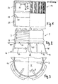
Figur 1 und 2 zeigen links im Axialschnitt, rechts in Seitenansicht die Überkappe bzw. Schraubkappe der ersten Ausführungsform.Figur 3 ist eine Teil-Draufsicht auf die Schraubkappe nachFigur 2.- Figur 4 zeigt in Seitenansicht die Mündung einer Flasche, die zur Anbringung von Verschlüssen nach der Erfindung geeignet ist.
Figur 5 zeigt links im Axialschnitt, rechts in Seitenansicht Überkappe und Schraubkappe mit Abreißelementen nach dem erstmaligen Verschließen der Mündung.- Figur 6 und 7 zeigen links im Axialschnitt, rechts in Seitenansicht die Überkappe bzw. Schraubkappe der zweiten Ausführungsform.
- Figur 8 ist eine Teil-Draufsicht auf die Schraubkappe nach
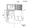
Figur 7. Figur 9 zeigt Schraubkappe und Überkappe entsprechend Figur 6 bis 8 auf einer Faschenmündung nach dem ersten Zusammenschrauben von Schraubkappe und Überkappe und bevor die Originalitätssicherung in Funktion tritt.
- 1 and 2 show on the left in axial section, on the right in side view the top cap or screw cap of the first embodiment.
- FIG. 3 is a partial top view of the screw cap according to FIG. 2.
- Figure 4 shows a side view of the mouth of a bottle which is suitable for attaching closures according to the invention.
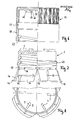
- Figure 5 shows on the left in axial section, on the right in side view, the overcap and screw cap with tear-off elements after the mouth has been closed for the first time.
- 6 and 7 show on the left in axial section, on the right in side view the overcap or screw cap of the second embodiment.
- FIG. 8 is a partial top view of the screw cap according to FIG. 7.
- Figure 9 shows the screw cap and overcap corresponding to Figures 6 to 8 on a bottle mouth after the first screwing together of the screw cap and overcap and before the tamper-evident function comes into operation.
Wie die Figuren 1 bis 5 zeigen, hat die Schraubkappe 1 ein Innengewinde 3 für die Gewindemündung 2 einer Flasche. An der Stirnfläche 5 der Schraubkappe sind sechs etwa radial gerichtete, rippenförmige Vorsprünge 7 vorgesehen. Gleichartige Vorsprünge 18 sind an der inneren Stirnfläche der Überkappe 14 vorhanden. Die Vorsprünge haben zueinander parallele Flanken 9 bzw. 20, die in axialen oder achsparallelen Ebenen liegen.As FIGS. 1 to 5 show, the
Die Überkappe 14 hat ein Stück oberhalb ihres Randes eine relativ breite Ringnut 23, während die Schraubkappe an ihrer Außenseite einen Ringwulst 26 hat, der unter einigem Abstand von dem offenen Ende der Schraubkappe angeordnet ist. Nach dem Aufprellen der Schraubkappe auf die Überkappe kann sich der Ringwulst 26 axial innerhalb der Ringnut 23 bewegen. Die Schraubkappe ist dadurch innerhalb der Überkappe mit axialem Spiel unverlierbar gehaltert. In der einen Extremstellung berühren die Vorsprünge 7 der Schraubkappe die Stirnfläche 16 der Überkappe, in der anderen Extremstellung stößt der Ringwulst 26 gegen eine Schulter 28 an dem unteren Rande der Ringnut 23.The
An der Innenwand der Überkappe 14 sind, über deren Umfang gleichmäßig verteilt, drei achsparallele Rippen 30 angeordnet, die ein Klappern der Überkappe auf der Schraubkappe verhindern.On the inner wall of the
Gewindemündungen 2 an Behältern oder Flaschen, die zur Aufnahme einer Schraubkappe mit Originalitätssicherung geeignet sind, haben einen Haltewulst 32 (Figur 4), im allgemeinen dicht unterhalb eines Außengewindes 34.Threaded
Zur Originalitätssicherung dienen Abreißelemente 36, die am Rand der Schraubkappe 1 durch Abreißstege 38 gehaltert sind. Bei dem dargestellten Ausführungsbeispiel sind vier Abreißelemente 36 vorgesehen, und jedes ist durch drei Abreißstege 38 gehaltert. Die Abreißelemente 36 sind miteinander durch Verbindungsstege 40 verbunden. In dem in Figur 2 dargestellten Herstellungszustand sind die Abreißelemente 36 Teile einer Hohlkegelfläche mit einem Zentriwinkel von etwa 30°. Bis auf die Verbindungsstege 40 sind sie voneinander durch V-förmige Ausschnitte 42 getrennt. Der Öffnungswinkel jedes Ausschnittes beträgt ebenfalls ca. 30°. An der Innenwandung jedes der Abreißelemente ist eine Kralle 44 in Form einer ringförmigen Rippe vorgesehen. Die Krallen sind zum Hintergreifen des Haltewulstes 32 der Mündung 2 bestimmt. An seiner Außenwandung, und zwar am unteren Rande, hat jedes Abreißelement einen Ringflansch 46. Wie Figur 5 zeigt, macht dieser Ringflansch, der nach dem erstmaligen Verschließen unter dem Rand der Überkappe vorsteht, kenntlich, daß der Verschluß noch nicht geöffnet worden ist.Tear-off
Zur Minderung der Reibung zwischen Schraubkappe und Überkappe hat jedes Abreißelement 36 zwei äußere Rippen 48, die etwa parallel zu Erzeugenden der Kegefläche der Abreißelemente verlaufen.To reduce the friction between the screw cap and the overcap, each tear-off
Die Schraubkappe wird zusammen mit den Abreißelementen in der in Figur 2 und 3 dargestellten Lage durch Spritzgießen hergestellt.The screw cap is produced together with the tear-off elements in the position shown in FIGS. 2 and 3 by injection molding.
Zum Verschließen der Mündung wird zunächst die Schraubkappe z.B. von einer Verschließmaschine auf die Mündung der Flasche gedreht, wobei die Abreißelemente 36 und ihre Krallen 44 ohne weiteres über das Außengewinde 34 und den Haltewulst 32 der Mündung greifen. Anschließend wird die Überkappe 14 in axialer Richtung über die Schraubkappe 1 geprellt, so daß sich dann die Lage nach Figur 5 ergibt, bei der der Ringwulst 26 der Schraubkappe 1 in die Ringnut 23 der Überkappe 14 eingreift. Die Überkappe ist damit an der Schraubkappe unverlierbar gehaltert. Der Randabschnitt 29 der überkappe hat die Abreißelemente 36 einwärts gedrückt, so daß ihre Krallen 44 hinter, d. h. unter den Haltewulst 32 der Mündung greifen. Die V-förmigen Ausschnitte 42 zwischen den Abreißelementen haben sich zu einem Schlitz verengt. Die Unterkanten 50 der Abreißelemente bilden nun Bögen, während sie im Herstellungszustand in einer Radialebene lagen.To close the mouth, the screw cap is first turned, for example by a capping machine, onto the mouth of the bottle, the tear-off
Falls erforderlich, kann der Verschluß noch fester zugeschraubt werden, wobei die Vorsprünge 18 der Überkappe die Vorsprünge 7 der Schraubkappe mitnehmen.If necessary, the closure can be screwed even more tightly, the
Zum erstmaligen Abschrauben muß die Überkappe gegen die Schraubkappe gedrückt wwerden, damit die Vorsprünge 18 der Überkappe die Vorsprünge 7 und mit ihnen die Schraubkappe in Drehrichtung mitnehmen können. Hierbei hält zwansläufig der Randabschnitt 29 die Abreißelemente 36 einwärts gedrückt und damit die Krallen 44 unterhalb des Haltewulstes 32 der Mündung fest, so daß sich die Abreißelemente 36 nicht aufwärts bewegen können. Während die Schraubkappe aufwärts gedreht wird, müssen infolge dessen die Abreißstege 38 durchgerissen werden. Die Abreißelemente 36 werden also von der Innenkappe 1 getrennt, wodurch erkennbar wird, daß der Verschluß geöffnet worden ist.For the first unscrewing, the overcap must be pressed against the screw cap so that the
Das zweite Ausführungsbeispiel, dargestellt in den Figuren 6 bis 9, unterscheidet sich vom ersten dadurch, daß sich die Überkappe 14 auf die Schraubkappe 1 schrauben läßt. Zu diesem Zweck ist an der Außenwand der Schraubkappe, nahe ihrem unteren Rande ein mehrgängiges, hier dreigängiges Außengewinde 60 vorgesehen und an der Überkappe 14 am unteren Rande ihres Randabschnittes 29 ein entsprechendes Innengewinde 62.The second exemplary embodiment, shown in FIGS. 6 to 9, differs from the first in that the
Die Kappe hat an ihrer inneren Stirnfläche 16 Vorsprünge 64 mit Flanken 66 und 68. Während die Flanken 66 in achsparallelen oder axialen Ebenen liegen, haben die Flanken 68 eine Neigung gegenüber der Stirnfläche 16, die zwischen 30 und 60° liegt, insbesondere etwa 45° beträgt. Hierdurch ergibt sich eine Kindersicherung, was unten beschrieben wird.The cap has 16
Im übrigen gleichen beide Ausführungsformen einander in ihren funktionswesentlichen Teilen.Otherwise, both embodiments are identical in their functionally essential parts.
Schon vor dem Verschließen einer Mündung wird die Überkappe 14 auf die Innenkappe 1 in eine Lage nach Figur 9 geschraubt. Hierbei stehen die Abreißelemente 36 unbehindert nach außen, ebenso wie in Figur 7 und 8. Das Zuschrauben der Überkappe auf die Schraubkappe wird zunächst dadurch beendet, daß die Anfänge des Außengewindes 60 der Schraubkappe 1 gegen die Enden der Innengewinde 62 der Überkappe stoßen. Wird der Verschluß in dieser Weise auf die Mündung 2 gedreht, so reicht das hierdurch zwischen beiden Kappen übertragbare Drehmoment zum Zuschrauben der Schraubkappe 1 auf das Außengewinde 34 der Mündung aus. Wird dann mit erhöhtem Drehmoment weitergedreht und/oder die Überkappe aufgeprellt, so weitet sich der Randabschnitt 29 auf und rutscht über das Außengewinde 60, so weit, bis dieses in die Ringnut 23 gerät. Hierdurch werden wiederum beide Verschlußteile aneinander unverlierbar gehaltert.Even before a mouth is closed, the
Außerdem greifen nun die Vorsprünge 64 und 7 in Drehrichtung hintereinander. Falls erforderlich, kann der Verschluß nun fester zugeschraubt werden. Bei der axialen Abwärtsbewegung der Überkappe 14 gegenüber der Schraubkappe 1 drückt, wie beim ersten Ausführungsbeispiel, der Randabschnitt 29 die Abreißelemente 36 einwärts, so daß die Krallen 44 unter den Haltewulst 32 der Mündung greifen.In addition, the
Beim Abschrauben muß wiederum die Überkappe 14 gegen die Mündung gedrückt werden. Der Verschluß hat die an sich bekannte Wirkung einer Kindersicherung. Versucht man zu öffnen, indem man lediglich die Überkappe entgegen dem Uhrzeigersinne dreht, so dreht sie sich entweder leer um oder die schrägen Flanken 68 der Vorsprünge 64 der Überkappe führen eine Ratschenbewegung an den Vorsprüngen 7 der Schraubkappe aus, ohne daß die Schraubkappe mitgenommen wird. Erst wenn man eine ausreichend große Kraft in axialer Richtung gegen die Mündung ausübt, können die schrägen Flanken 68 die Vorsprünge 7 mitnehmen, wobei die Schraubkappe l abgeschraubt wird.When unscrewing the
Der Randabschnitt 29 hält wiederum während des Abschraubvorganges die Abreißelemente 36 gegen die Mündung gedrückt und die Krallen 44 unterhalb des Haltewulstes 32 der Mündung fest, so daß die Abreißstege 38 durchgerissen werden müssen.The
- 1 Schraubkappe1 screw cap
- 2 Gewindemündung2 threaded mouth
- 3 Innengewinde3 internal threads
- 5, 16 Stirnfläche5, 16 end face
- 7, 18 Vorsprung7, 18 lead
- 9 Flanke9 flank
- 14 Überkappe14 overcap
- 20 Flanke20 flank
- 23 Ringnut23 ring groove
- 26 Ringwulst26 ring bead
- 28 Schulter28 shoulder
- 29 Randabschnitt29 edge section
- 30 Rippe30 rib
- 32 Haltewulst32 retaining bead
- 34 Außengewinde34 external thread
- 36 Abreißelement36 tear-off element
- 38 Abreißsteg38 tear-off bar
- 40 Verbindungssteg40 connecting bridge
- 42 Ausschnitt42 detail
- 44 Kralle44 claw
- 46 Ringflansch46 ring flange
- 48 Rippe48 rib
- 50 Unterkante50 bottom edge
- 60 Außengewinde60 external threads
- 62 Innengewinde62 internal thread
- 64 Vorsprung64 head start
- 66, 68 Flanke66, 68 flank
Claims (14)
Applications Claiming Priority (2)
| Application Number | Priority Date | Filing Date | Title |
|---|---|---|---|
| DE3336908 | 1983-10-11 | ||
| DE19833336908 DE3336908A1 (en) | 1983-10-11 | 1983-10-11 | ORIGINAL LOCKING PLASTIC |
Publications (2)
| Publication Number | Publication Date |
|---|---|
| EP0137352A2 true EP0137352A2 (en) | 1985-04-17 |
| EP0137352A3 EP0137352A3 (en) | 1986-01-08 |
Family
ID=6211514
Family Applications (1)
| Application Number | Title | Priority Date | Filing Date |
|---|---|---|---|
| EP84111027A Withdrawn EP0137352A3 (en) | 1983-10-11 | 1984-09-15 | Plastic tamper-proof closure |
Country Status (4)
| Country | Link |
|---|---|
| US (1) | US4562931A (en) |
| EP (1) | EP0137352A3 (en) |
| JP (1) | JPS6099860A (en) |
| DE (1) | DE3336908A1 (en) |
Cited By (6)
| Publication number | Priority date | Publication date | Assignee | Title |
|---|---|---|---|---|
| WO1987002009A1 (en) * | 1985-10-03 | 1987-04-09 | Dawson Electrics Pty. Ltd. | Improvements in or relating to tamper evident closures |
| EP0343534A2 (en) * | 1988-05-27 | 1989-11-29 | Walter Sarstedt Geräte und Verbrauchsmaterial für Medizin und Wissenschaft | Container for preserving liquids, in particular bodily liquids |
| EP0214711B1 (en) * | 1985-08-29 | 1992-01-22 | Kerr Glass Manufacturing Corporation | Tamper-evident child-resistant closure |
| GB2454511A (en) * | 2007-11-09 | 2009-05-13 | Beeson & Sons Ltd | Tamper evident container closure with overcap |
| CN102482006A (en) * | 2009-08-25 | 2012-05-30 | 超力公司 | Closure with obliquely angled cam surfaces on inner and outer parts |
| EP3476760A4 (en) * | 2016-06-28 | 2020-03-18 | Gomez Cao Innovations & Inventions, S.L. | Cap |
Families Citing this family (32)
| Publication number | Priority date | Publication date | Assignee | Title |
|---|---|---|---|---|
| DE8805665U1 (en) * | 1988-04-29 | 1988-07-07 | Rohe, Karl-Heinz, 3490 Bad Driburg, De | |
| US4805791A (en) * | 1988-05-04 | 1989-02-21 | Continental White Cap, Inc. | Band with lock ring for tamper-evident cap |
| GB2257693B (en) * | 1991-07-10 | 1995-08-02 | Beeson & Sons Ltd | A container and closure |
| US5411157A (en) * | 1990-05-30 | 1995-05-02 | Beeson And Sons Limited | Container and the manufacture thereof |
| GB2262280B (en) * | 1991-12-11 | 1995-09-20 | Beeson & Sons Ltd | A container neck and a closure therefor |
| US5100011A (en) * | 1991-04-05 | 1992-03-31 | The West Company, Incorporated | Tamper evident closure |
| US5588545A (en) * | 1991-09-23 | 1996-12-31 | Beeson And Sons Limited | Child-resistant and elderly friendly closure for containers |
| JP3552720B2 (en) * | 1992-11-13 | 2004-08-11 | ビーソン・アンド・サンズ・リミテッド | Improvement on tamper-evident proof ring of container seal |
| GB9320389D0 (en) * | 1993-10-04 | 1993-11-24 | Beeson & Sons Ltd | Improvements relating to container closures |
| US5477972A (en) * | 1994-06-02 | 1995-12-26 | Lester; William M. | Tamper evident closure device for bottles and the like |
| US5456374A (en) * | 1994-09-19 | 1995-10-10 | Beck; Matthew R. | Tamper evident container closure |
| US5680965A (en) * | 1996-01-29 | 1997-10-28 | Beck; Matthew R. | Tamper evident container closure |
| DE29807243U1 (en) * | 1998-04-22 | 1999-08-26 | Sanner Friedr Gmbh Co Kg | Childproof and tamper-evident container closure |
| US6382444B1 (en) * | 1999-03-17 | 2002-05-07 | Sentinel Packaging Systems, Inc. | Tamper-evident plastic closure system with snap-on band |
| ITTV20020025A1 (en) * | 2002-03-06 | 2003-09-08 | Alessandro Tomasella | CLOSING DEVICE, PARTICULARLY FOR BOTTLES AND / OR CONTAINERS |
| WO2005012129A1 (en) * | 2003-08-01 | 2005-02-10 | Liqui-Box Canada Inc. | Tamper evident fitment assembly |
| GB0503623D0 (en) * | 2005-02-22 | 2005-03-30 | Camlab Ltd | Secure sample collection |
| WO2006089432A1 (en) * | 2005-02-28 | 2006-08-31 | Stanpac Inc. | Composite closures for containers |
| US7549547B2 (en) * | 2005-06-06 | 2009-06-23 | Berry Plastics Corporation | Composite two-piece tamper-evident closure with a seal-delay-release feature and a method therefor |
| US20070272647A1 (en) * | 2006-03-31 | 2007-11-29 | Long Charles J | Closure with vertical tear bands |
| US20090014404A1 (en) * | 2007-07-10 | 2009-01-15 | Berry Plastics Corporation | Convertible container closure |
| RU2507137C2 (en) * | 2008-04-30 | 2014-02-20 | Клоужер Системз Интернэшнл, Инк. | Package with indication of opening with improved characteristics of opening |
| US20090277861A1 (en) * | 2008-05-08 | 2009-11-12 | Long Jr Charles J | Closure with tamper evident strip |
| US8763830B2 (en) * | 2010-10-15 | 2014-07-01 | Closure Systems International Inc. | Tamper-evident closure having tamper-indicating pilfer band with projections and package including the tamper-evident closure |
| CN104309919B (en) * | 2013-09-30 | 2017-02-22 | 青海春天药用资源科技利用有限公司 | Burglarproof bottle cap and burglarproof bottle |
| EP3219637A1 (en) | 2014-02-14 | 2017-09-20 | Closure Systems International Inc. | Improved tamper-evident closure |
| US10407225B2 (en) | 2017-11-07 | 2019-09-10 | Closure Systems International Inc. | Closure and package that vents at high pressure |
| CR20220114A (en) | 2019-10-07 | 2022-05-23 | Closure Systems Int Inc | Flip-top closure |
| USD996968S1 (en) | 2021-05-17 | 2023-08-29 | Closure Systems International Inc. | Closure |
| USD996967S1 (en) | 2021-05-17 | 2023-08-29 | Closure Systems International Inc. | Closure |
| US11945625B2 (en) | 2022-06-24 | 2024-04-02 | Closure Systems International Inc. | Package with closure |
| US11801977B1 (en) | 2022-12-02 | 2023-10-31 | Closure Systems International Inc. | Package with one-piece closure |
Citations (3)
| Publication number | Priority date | Publication date | Assignee | Title |
|---|---|---|---|---|
| DE2307205A1 (en) * | 1973-02-14 | 1974-08-22 | Neuro Plast Gmbh & Co Kg | SECURITY BOTTLE CAP |
| EP0021985A1 (en) * | 1979-06-22 | 1981-01-07 | André Chazeau | Closure guaranteeing the non-opening of a container |
| FR2464199A1 (en) * | 1979-09-05 | 1981-03-06 | Giraud Gallaire Sa Ets | Sealed screwed bottle stopper - has locking ring held by four tabs integral with stopper |
Family Cites Families (7)
| Publication number | Priority date | Publication date | Assignee | Title |
|---|---|---|---|---|
| DE1959264A1 (en) * | 1969-11-26 | 1971-06-16 | Gerhard Mueller | Safety screw cap for bottles and similar containers |
| US3926326A (en) * | 1971-03-31 | 1975-12-16 | Hermann Grau | Safety closure |
| DE2115741B1 (en) * | 1971-03-31 | 1972-06-29 | Grau, Hermann, 7071 Lindach | Safety lock |
| DE2216343B2 (en) * | 1972-04-05 | 1975-05-15 | Hermann 7071 Lindach Grau | Safety screw cap |
| DE2943548A1 (en) * | 1979-10-27 | 1981-05-07 | Alcoa Deutschland Gmbh Verpackungswerke, 6520 Worms | Screwed bottle neck cap assembly - has internally-knurled outer cap engaging with inner one when pressed down |
| GB2066792B (en) * | 1979-11-19 | 1983-10-26 | Deussen Stella Kg | Container closure with childproof lock and original package seal |
| US4474301A (en) * | 1983-03-14 | 1984-10-02 | Johnsen & Jorgensen (Plastics) Ltd. | Tamper-resistant and childproof closure |
-
1983
- 1983-10-11 DE DE19833336908 patent/DE3336908A1/en not_active Withdrawn
-
1984
- 1984-09-15 EP EP84111027A patent/EP0137352A3/en not_active Withdrawn
- 1984-10-09 US US06/658,750 patent/US4562931A/en not_active Expired - Fee Related
- 1984-10-11 JP JP59211574A patent/JPS6099860A/en active Pending
Patent Citations (3)
| Publication number | Priority date | Publication date | Assignee | Title |
|---|---|---|---|---|
| DE2307205A1 (en) * | 1973-02-14 | 1974-08-22 | Neuro Plast Gmbh & Co Kg | SECURITY BOTTLE CAP |
| EP0021985A1 (en) * | 1979-06-22 | 1981-01-07 | André Chazeau | Closure guaranteeing the non-opening of a container |
| FR2464199A1 (en) * | 1979-09-05 | 1981-03-06 | Giraud Gallaire Sa Ets | Sealed screwed bottle stopper - has locking ring held by four tabs integral with stopper |
Cited By (9)
| Publication number | Priority date | Publication date | Assignee | Title |
|---|---|---|---|---|
| EP0214711B1 (en) * | 1985-08-29 | 1992-01-22 | Kerr Glass Manufacturing Corporation | Tamper-evident child-resistant closure |
| WO1987002009A1 (en) * | 1985-10-03 | 1987-04-09 | Dawson Electrics Pty. Ltd. | Improvements in or relating to tamper evident closures |
| EP0343534A2 (en) * | 1988-05-27 | 1989-11-29 | Walter Sarstedt Geräte und Verbrauchsmaterial für Medizin und Wissenschaft | Container for preserving liquids, in particular bodily liquids |
| EP0343534A3 (en) * | 1988-05-27 | 1990-11-28 | Sarstedt Walter Geraete | Container for preserving liquids, in particular bodily liquids |
| GB2454511A (en) * | 2007-11-09 | 2009-05-13 | Beeson & Sons Ltd | Tamper evident container closure with overcap |
| GB2454511B (en) * | 2007-11-09 | 2012-03-07 | Beeson & Sons Ltd | Container closure with overcap |
| CN102482006A (en) * | 2009-08-25 | 2012-05-30 | 超力公司 | Closure with obliquely angled cam surfaces on inner and outer parts |
| CN102482006B (en) * | 2009-08-25 | 2014-07-16 | 超力公司 | Closure With Obliquely Angled Cam Surfaces On Inner And Outer Parts |
| EP3476760A4 (en) * | 2016-06-28 | 2020-03-18 | Gomez Cao Innovations & Inventions, S.L. | Cap |
Also Published As
| Publication number | Publication date |
|---|---|
| JPS6099860A (en) | 1985-06-03 |
| DE3336908A1 (en) | 1985-04-18 |
| US4562931A (en) | 1986-01-07 |
| EP0137352A3 (en) | 1986-01-08 |
Similar Documents
| Publication | Publication Date | Title |
|---|---|---|
| EP0137352A2 (en) | Plastic tamper-proof closure | |
| EP0049876A1 (en) | Tamperproof screw closure | |
| DE3233805C2 (en) | ||
| DE3319709A1 (en) | INTERVENTION DISCLOSURE | |
| EP0225394A1 (en) | Tamper-proof closure | |
| DE2421292B2 (en) | CHILD-RESISTANT LOCKING FOR A CONTAINER | |
| DE2226906B2 (en) | Container cap | |
| DE2753080C2 (en) | Closing cap with tamper evident | |
| EP0623522A1 (en) | Child proof screw cap | |
| DE1804099B2 (en) | Container with screw cap | |
| EP0123810A1 (en) | Child-resistant closure | |
| DE2515565A1 (en) | CLOSURE FOR CONTAINERS, IN PARTICULAR FOR MEDICAL BOTTLES | |
| DE2638351C3 (en) | Guarantee cap for bottles | |
| CH647731A5 (en) | BOTTLE WITH SCREW CAP AND ORIGINALITY LOCK. | |
| EP0297160B1 (en) | Child-proof screw cap | |
| DE1914313A1 (en) | Inviolable lock | |
| DE3233806A1 (en) | Closure cap, preferably with tamper-proof safeguard | |
| DE3108518C2 (en) | ||
| DE3144924C2 (en) | ||
| EP0090143A1 (en) | Child-resistant press-and-turn closure | |
| EP0060983B1 (en) | Container with safety closure | |
| EP0052260B1 (en) | Child-resistant closure | |
| DE102005040745A1 (en) | Tamper evident closure for containers | |
| EP0570760B1 (en) | Closure cap with tamper indicating element | |
| DE3715862C2 (en) |
Legal Events
| Date | Code | Title | Description |
|---|---|---|---|
| PUAI | Public reference made under article 153(3) epc to a published international application that has entered the european phase |
Free format text: ORIGINAL CODE: 0009012 |
|
| AK | Designated contracting states |
Designated state(s): AT BE CH DE FR GB IT LI NL SE |
|
| PUAL | Search report despatched |
Free format text: ORIGINAL CODE: 0009013 |
|
| AK | Designated contracting states |
Designated state(s): AT BE CH DE FR GB IT LI NL SE |
|
| STAA | Information on the status of an ep patent application or granted ep patent |
Free format text: STATUS: THE APPLICATION IS DEEMED TO BE WITHDRAWN |
|
| 18D | Application deemed to be withdrawn |
Effective date: 19860909 |
|
| RIN1 | Information on inventor provided before grant (corrected) |
Inventor name: BRACH, ULRICH Inventor name: PERSCH, ALOIS |