EP0137147A2 - Pattern processing system - Google Patents
Pattern processing system Download PDFInfo
- Publication number
- EP0137147A2 EP0137147A2 EP84108328A EP84108328A EP0137147A2 EP 0137147 A2 EP0137147 A2 EP 0137147A2 EP 84108328 A EP84108328 A EP 84108328A EP 84108328 A EP84108328 A EP 84108328A EP 0137147 A2 EP0137147 A2 EP 0137147A2
- Authority
- EP
- European Patent Office
- Prior art keywords
- pattern
- square
- plural
- squares
- bits
- Prior art date
- Legal status (The legal status is an assumption and is not a legal conclusion. Google has not performed a legal analysis and makes no representation as to the accuracy of the status listed.)
- Granted
Links
Images


Classifications
-
- G—PHYSICS
- G06—COMPUTING; CALCULATING OR COUNTING
- G06K—GRAPHICAL DATA READING; PRESENTATION OF DATA; RECORD CARRIERS; HANDLING RECORD CARRIERS
- G06K15/00—Arrangements for producing a permanent visual presentation of the output data, e.g. computer output printers
- G06K15/02—Arrangements for producing a permanent visual presentation of the output data, e.g. computer output printers using printers
- G06K15/10—Arrangements for producing a permanent visual presentation of the output data, e.g. computer output printers using printers by matrix printers
Definitions
- This invention relates to a device for processing dot matrix patterns that represent various characters or the like for generating image data as a page to be printed by a page printer.
- Althouqh page printers have been developed, which have a function for generating image data as a page to be printed by loading various patterns in any location in a buffer, it cannot be said that such printers have sufficient abilities in their speed and flexibility for processing the patterns.
- a typical conventional page printer is disclosed, for example, in U.S. Patent No. 4,300,206. Although it has such a function that generates a page image by selectively transferring various patterns in a raster memory to any location in a strip buffer under control of a microprocessor, it has such shortcomings that it fails to provide effective means to rotate the patterns. Of course, it can be arranged to previously store, in addition to original patterns, those rotated by predetermined angles in a pattern memory, which are selectively taken out if necessary. However, if kanji patterns, which are of various types, are used in addition to alphanumerics, or if there are various pattern size, such printer is unsuitable, because a pattern memory of a large capacity is required.
- U.S. Patent No. 3,976,982 A conventional technique relating to the rotation of patterns is shown in U.S. Patent No. 3,976,982.
- the image processor disclosed therein has a configuration to obtain in a memory the images that are original ones rotated in any angle by 90°. That is, the rotation of the images is attained by transferring the original ones bit by bit to the memory, and by appropriately selecting locations to be written with them.
- This technique has such shortcomings that its processing speed is low because the image is processed bit by bit.
- This invention intends to provide a pattern processing device that can quickly process patterns with rotation by relatively small number of hardwares.
- the pattern processing device is characterized by that it handles each pattern by separating it into small segments called squares.
- Various patterns are stored in a pattern storage so that they can be read by square.
- Each square being read is transferred to a raster buffer through a rotating means, and loaded in a storage location that is specified by an addressing means.
- the rotating means has a function that gates a plurality of bits in each square to an output line in a different manner in response to control information "relating to the pattern rotation.
- the addressing means acts in combination of a reference address and offsets to sequentially specify a plurality of storage locations in the raster buffer in which a series of squares are stored.
- this invention can attain the rotation of pattern by the action of the relatively simple rotating means and the addressing means, it has such advantages that the number of required hardwares can be reduced, and that the transferring speed of patterns to the raster buffer is not affected by performance and non- performance of rotating operation. Further, the pattern processing device according to the invention can cope with changes of pattern size to be handled without changing its overall configuration. That is, the change of pattern size requires only to determine the pattern to be integral multiples of square, and to change the type of offset used in the addressing means.
- the patterns to be handled are not restricted to characters and symbols, and may be patterns representing any image including, for example, an image of various ruler lines, etc.
- Figure 1 shows an arrangement of the pattern processor according to the invention. It comprises a pattern storage 21 storing patterns of various characters or the like, a raster buffer 22 for temporarily storing printing data created by a plurality of selected patterns, and a pel generator 23 for controlling transfer of patterns from the pattern storage 21 to the raster buffer 22, and is controlled by a processor 20.
- the raster buffer 22 is further attached with a raster generator 24 that takes out the printing data in the buffer raster by raster, and transfers it to a printer (not shown).
- Each pattern stored in the pattern storage 21 is partitioned by a unit of square consisting of n x n bits so as to facilitate rotation of the patterns.
- each pattern consists of a dot matrix of 8 rows by 8 columns as shown in Figure 2, and that one square consists of dots or bits of 2 rows by 2 columns, as shown in Figure 4.
- each pattern consists of a square Sij of 4 rows by 4 columns as shown in Figure 3.
- each of partitions corresponds to one bit, wherein an empty partition corresponds to bit 0, a shaded one to bit 1.
- the pattern shown, for example, represents A of alphabet.
- the numerals 0 to 3 in four partitions of one square in Figure 4 represent the bit number in the square.
- Figure 5 shows the relation between the squares belonging to the pattern in Figure 2 and the addresses of the pattern storage 21. While an example is shown wherein an address is assigned to every four bits of squares, it is possible to store two squares of even number and odd number as two half bytes of a sequential storage location that is addressed byte by byte.
- the pel generator 23 comprises various components contained in the block encircled by the broken lines in Figure 1.
- a control circuit 31 decodes commands from the processor 20, and controls the operation timing of other components by controlling or timing signals on lines 33. The connection between the lines 33 and other components is omitted, because it should be easily understood by those skilled in the art.
- PSA pattern storage address
- PO pattern orientation
- BA base address
- OTA offset table address
- the PSA generator 25 is loaded with an address specifying a storage location in the pattern storage 21 that stores the first square of the pattern to be read.
- the generator 25 sequentially specifies storage locations for subsequent squares by increasing the address under the control of the control circuit 31.
- Each square being read from the specified storage location is transferred to the raster buffer 22 through a line 34, a square rotator 29 and a line 35.
- the lines 34 and 35 actually consists of four lines respectively to transfer four bits of the square in parallel.
- the operation of the square rotator 29 is controlled by the pattern orientation information being loaded in the PO register 26. That is, this information indicates that a pattern, consequently individual squares belonging to it, should be rotated according to one of predetermined rotating angles.
- the selectable rotating angles are, for example, 0° (no rotation), 90°, 180° and 270° in the counterclockwise rotation.
- Figure 6 shows a detailed configuration of the square rotator 29 to perform such rotating operation.
- input lines 80, 81, 82 and 83 correspond to the line 34 in Figure 1 and transmit the bits of the bit number 0, 1, 2 and 3 in the square respectively.
- output lines 90, 91, 92 and 93 correspond to the line 35 in Figure 1 and respectively transfers bits to be written, as the bit number 0, 1, 2 and 3 in the square, in one square storage location in the raster buffer 22.
- the square rotator 29 contains a group of data selectors (gates). As shown, all input lines 80 to 83 are connected to each data selector. Each data selector has a function gating the bit from either one of four input lines to the output line according to the orientation information from the PO register 26.
- the orientation information may be of two bits, and specify 0°, 90°, 180° and 270° by 00, 01, 10 and 11. All of the data selectors 70 to 73 select the bit on the input line related to either one of a, b, c or d according to the orientation information of either one of 00, 01, 10 or 11 all at once, and send out it to the output lines. Thus, the rotation of each square is attained.
- Figure 7 (B) shows a relation between the rotation angles and four bits on the output lines when the square shown at (A) is processed by the square rotator in Figure 6, and appearances of the square after processing.
- Figure 8 is referred to explain the operation for writing squares successively appearing on the output of the square rotator 29 into the raster buffer 22. It schematically shows a relation between the raster buffer 22 partitioned so that the address can be assigned to each square and the patterns stored therein.
- a partition defined by the broken lines is a storage location for storing a square, which consists of 2 x 2 bit positions.
- the raster buffer 22 is constituted to have a capacity of 2048 squares (4096 bits) in X-direction and 128 squares (256 bits) in Y-direction. That is, it has a capacity of 128k bytes.
- Such capacity is not sufficient to contain the printing data for one page to be printed at a time, which may be overcome by partitioning the page into a plurality of sections, so that the buffer can successively contain the printing data for each section. It may be also possible to continuously process successive sections by utilizing an addressing technique of wraparound type. Of course, it may possible to employ a buffer having a capacity enough to contain the printing data for one page at a time.
- the width of the raster buffer in X-direction corresponds to the printable width in a direction normal to the feeding direction of the paper.
- An address is assigned to each square storage location, which address, as shown in Figure 9, consists of an X-direction address of 11 bits indicating the position in that direction, and a Y-direction address of 7 bits indicating the position in that direction.
- the square storage locations that are sequentially written with a plurality of squares belonging to a certain pattern being transferred through the square rotator 29 are specified by addresses that are generated by the operation of the BA register 27, the OTA generator 28, the offset table 30 and the address calculator 32 in the pel generator 23 of Figure 1.
- the BA register 27 is loaded with a base address that specifies a location to be a reference of the square storage locations in which the squares belonging to one pattern are written. Then, addresses for sequentially specifying these square storage locations are generated by adding a series of offsets ( ⁇ X, ⁇ Y) representing subsequent displacement to the base address (X, Y) from the A register 27.
- a series of offsets are sequentially supplied from the offset table 30 through the line 40 under the control of the OTA generator 28, the addition to the base address being performed by the address calculator 32.
- the addresses generated are used to specify the square storage locations of the raster buffer 22 through the line 36.
- the square storage location specified by the base address is those indicated by Bl and B2 in Figure 8. That is, it is arranged that, regardless of the rotation of the pattern received, the one at the upper left corner of a group of square storage locations for receiving the pattern is specified by the base address.
- the base address is the smallest one of addresses for the group of square storage locations (except when using the addressing technique of the wraparound type).
- the offset table 30 contains four tables or areas that includes four groups of offsets relating to the rotation of 0°, 90°, 180° and 270° respectively. Also, while, in the example, it is assumed that the pattern has only one size, when patterns with different sizes are used, it becomes required to prepare different offset data for each size.
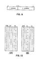
- Figure 10 (A) and (B) respectively shows contents of two tables or areas in the offset table 30 that is used to rotate a pattern consisting of 4 x 4 squares by 0° (no rotation) and 90°.
- Binary values in ⁇ X and AY columns represent offsets in X and Y directions.
- the first line of each table is specified by an offset table entry address that is first loaded in the OTA generator 28.
- the OTA generator 28 operates to read the contents of successive lines of the offset table to the line 40 by increasing the addresses relating to the table in synchronization with reading of successive squares from the pattern storage 21.
- Each line of the offset table also stores an end square bit (ESB) that becomes 1 only at the end of a series of offsets used in relation to a pattern, and that is read together with the offset.
- the control circuit 31 detects that transfer of all squares belonging to one pattern is completed, by detecting that ESB is 1, and generates an interruption signal so as to inform the processor 20 that the next pattern can be processed.
- writing the pattern 51 in Figure 8 is studied by referring to the table in Figure 10 (B).
- the printing data thus generated in the raster buffer 22 by the operation of the pel generator 23 is transferred raster by raster to the printer by the operation of the raster generator 24 through the line 39. That is, it is designed to transfer the content of the raster buffer 22 bit line by bit line (one bit in width in Y-direction, and 2048 bits in length in X-direction) with the representation of first to 256th raster shown in the right of Figure 8.
- the access is performed in the unit of square
- the raster generator 24 sequentially transfers a pair of rasters, for example the first and the second raster, it accesses same square line twice, takes out it through the line 37, and transfers only the upper bits 3 and 2 of each square in the first time, and only the lower bits 1 and 0 in the second time.
- the raster generator 24 performs such access operation by the address that is supplied on the line 38 by it.
- each square storage location is not arranged in a matrix of 2 rows by 2 columns, but actually arranged in a line to form a storage location of four bit width.
- a plurality of storage locations are not required as a whole to be arranged in a matrix of X- and Y-directions as shown in Figure 8, but accepted only if they are arranged in a sequence of physical addresses of 00000 to 3FFFF that are obtained by representing 18 bits of the format address shown in Figure 9 in the hexadecimal notation.
- Figure 8 shows overall arrangement of a plurality of storages, and the arrangement of four bit location in each storage by rearranging them for easy understanding of the relation with the pattern to be written.
- the pattern used may be of larger size, and the square may be larger than 2 x 2 bits in the relation to the pattern size. It is preferred to use a random access memory for the offset table 30 because it easily cope with the change of the pattern size, but of course a read only memory may be used.
- This invention allows relatively small amount of hardwares to quickly process patterns that required to be rotated in connection with the generation of the printing data for the page printer.
Abstract
Description
- This invention relates to a device for processing dot matrix patterns that represent various characters or the like for generating image data as a page to be printed by a page printer.
- Althouqh page printers have been developed, which have a function for generating image data as a page to be printed by loading various patterns in any location in a buffer, it cannot be said that such printers have sufficient abilities in their speed and flexibility for processing the patterns.
- A typical conventional page printer is disclosed, for example, in U.S. Patent No. 4,300,206. Although it has such a function that generates a page image by selectively transferring various patterns in a raster memory to any location in a strip buffer under control of a microprocessor, it has such shortcomings that it fails to provide effective means to rotate the patterns. Of course, it can be arranged to previously store, in addition to original patterns, those rotated by predetermined angles in a pattern memory, which are selectively taken out if necessary. However, if kanji patterns, which are of various types, are used in addition to alphanumerics, or if there are various pattern size, such printer is unsuitable, because a pattern memory of a large capacity is required.
- A conventional technique relating to the rotation of patterns is shown in U.S. Patent No. 3,976,982. The image processor disclosed therein has a configuration to obtain in a memory the images that are original ones rotated in any angle by 90°. That is, the rotation of the images is attained by transferring the original ones bit by bit to the memory, and by appropriately selecting locations to be written with them. This technique has such shortcomings that its processing speed is low because the image is processed bit by bit.
- Another example of conventional technique relating to the pattern rotation is shown in Japanese Patent Disclosure No. 105334/1975. It performs the rotation of patterns, when it becomes required, by once writing patterns read from a pattern storage in a storage for changing orientation, then by reading them in a direction different from the writing direction. Therefore, it is obvious that it has relatively large number of hardwares required to rotate the patterns, as well as needs longer time.
- This invention intends to provide a pattern processing device that can quickly process patterns with rotation by relatively small number of hardwares.
- The pattern processing device according to the invention is characterized by that it handles each pattern by separating it into small segments called squares. Each square consists of n rows x n columns bits (dots), wherein n is an integer larger than 1, and n=2 in a preferable embodiment. Various patterns are stored in a pattern storage so that they can be read by square. Each square being read is transferred to a raster buffer through a rotating means, and loaded in a storage location that is specified by an addressing means. The rotating means has a function that gates a plurality of bits in each square to an output line in a different manner in response to control information "relating to the pattern rotation. Further, the addressing means acts in combination of a reference address and offsets to sequentially specify a plurality of storage locations in the raster buffer in which a series of squares are stored.
- Because this invention can attain the rotation of pattern by the action of the relatively simple rotating means and the addressing means, it has such advantages that the number of required hardwares can be reduced, and that the transferring speed of patterns to the raster buffer is not affected by performance and non- performance of rotating operation. Further, the pattern processing device according to the invention can cope with changes of pattern size to be handled without changing its overall configuration. That is, the change of pattern size requires only to determine the pattern to be integral multiples of square, and to change the type of offset used in the addressing means. The patterns to be handled are not restricted to characters and symbols, and may be patterns representing any image including, for example, an image of various ruler lines, etc.
-
- Figure 1 shows a block diagram of a pattern processing device according to this invention,
- Figure 2 shows an example of a dot matrix pattern,
- Figure 3 shows relations between the pattern and squares,
- Figure 4 shows bit numbers in one square,
- Figure 5 shows relations between addresses and the squares in a pattern storage,
- Figure 6 shows a detailed configuration of a square rotator,
- Figure 7 shows manners of rotation of the squares according to the configuration of Figure 6,
- Figure 8 shows relations between a raster buffer and the pattern to be written therein,
- Figure 9 shows a format of addresses relating to the raster buffer, and
- Figure 10 shows contents of offset tables that are used for writing the pattern rotated by 0° (non-rotation) and 90° in the raster buffer.
- Figure 1 shows an arrangement of the pattern processor according to the invention. It comprises a
pattern storage 21 storing patterns of various characters or the like, araster buffer 22 for temporarily storing printing data created by a plurality of selected patterns, and apel generator 23 for controlling transfer of patterns from thepattern storage 21 to theraster buffer 22, and is controlled by aprocessor 20. Theraster buffer 22 is further attached with araster generator 24 that takes out the printing data in the buffer raster by raster, and transfers it to a printer (not shown). - Each pattern stored in the
pattern storage 21 is partitioned by a unit of square consisting of n x n bits so as to facilitate rotation of the patterns. For example, it is assumed that each pattern consists of a dot matrix of 8 rows by 8 columns as shown in Figure 2, and that one square consists of dots or bits of 2 rows by 2 columns, as shown in Figure 4. Thus, each pattern consists of a square Sij of 4 rows by 4 columns as shown in Figure 3. In Figure 2, each of partitions corresponds to one bit, wherein an empty partition corresponds tobit 0, a shaded one tobit 1. The pattern shown, for example, represents A of alphabet. In addition, thenumerals 0 to 3 in four partitions of one square in Figure 4 represent the bit number in the square. - Four bits in each square are not stored as in a form of matrix, but are stored by arranging them in a single line in a sequence of the
bit number pattern storage 21. Figure 5 shows the relation between the squares belonging to the pattern in Figure 2 and the addresses of thepattern storage 21. While an example is shown wherein an address is assigned to every four bits of squares, it is possible to store two squares of even number and odd number as two half bytes of a sequential storage location that is addressed byte by byte. - The
pel generator 23 comprises various components contained in the block encircled by the broken lines in Figure 1. Acontrol circuit 31 decodes commands from theprocessor 20, and controls the operation timing of other components by controlling or timing signals onlines 33. The connection between thelines 33 and other components is omitted, because it should be easily understood by those skilled in the art. Whenever it becomes required to transfer one pattern from thepattern storage 21 to theraster buffer 22, information required to such operation is loaded from theprocessor 20 to a pattern storage address (PSA)generator 25, a pattern orientation (PO)register 26, a base address (BA)register 27 and an offset table address (OTA)generator 28. - The
PSA generator 25 is loaded with an address specifying a storage location in thepattern storage 21 that stores the first square of the pattern to be read. Thegenerator 25 sequentially specifies storage locations for subsequent squares by increasing the address under the control of thecontrol circuit 31. Each square being read from the specified storage location is transferred to theraster buffer 22 through aline 34, asquare rotator 29 and aline 35. Thelines - The operation of the
square rotator 29 is controlled by the pattern orientation information being loaded in thePO register 26. That is, this information indicates that a pattern, consequently individual squares belonging to it, should be rotated according to one of predetermined rotating angles. The selectable rotating angles are, for example, 0° (no rotation), 90°, 180° and 270° in the counterclockwise rotation. Figure 6 shows a detailed configuration of thesquare rotator 29 to perform such rotating operation. - In Figure 6,
input lines line 34 in Figure 1 and transmit the bits of thebit number output lines line 35 in Figure 1 and respectively transfers bits to be written, as thebit number raster buffer 22. Thesquare rotator 29 contains a group of data selectors (gates). As shown, allinput lines 80 to 83 are connected to each data selector. Each data selector has a function gating the bit from either one of four input lines to the output line according to the orientation information from thePO register 26. For example, the orientation information may be of two bits, and specify 0°, 90°, 180° and 270° by 00, 01, 10 and 11. All of thedata selectors 70 to 73 select the bit on the input line related to either one of a, b, c or d according to the orientation information of either one of 00, 01, 10 or 11 all at once, and send out it to the output lines. Thus, the rotation of each square is attained. - As an example, Figure 7 (B) shows a relation between the rotation angles and four bits on the output lines when the square shown at (A) is processed by the square rotator in Figure 6, and appearances of the square after processing.
- Now, Figure 8 is referred to explain the operation for writing squares successively appearing on the output of the
square rotator 29 into theraster buffer 22. It schematically shows a relation between theraster buffer 22 partitioned so that the address can be assigned to each square and the patterns stored therein. A partition defined by the broken lines is a storage location for storing a square, which consists of 2 x 2 bit positions. In this example, theraster buffer 22 is constituted to have a capacity of 2048 squares (4096 bits) in X-direction and 128 squares (256 bits) in Y-direction. That is, it has a capacity of 128k bytes. Usually, such capacity is not sufficient to contain the printing data for one page to be printed at a time, which may be overcome by partitioning the page into a plurality of sections, so that the buffer can successively contain the printing data for each section. It may be also possible to continuously process successive sections by utilizing an addressing technique of wraparound type. Of course, it may possible to employ a buffer having a capacity enough to contain the printing data for one page at a time. The width of the raster buffer in X-direction corresponds to the printable width in a direction normal to the feeding direction of the paper. - An address is assigned to each square storage location, which address, as shown in Figure 9, consists of an X-direction address of 11 bits indicating the position in that direction, and a Y-direction address of 7 bits indicating the position in that direction.
- The square storage locations that are sequentially written with a plurality of squares belonging to a certain pattern being transferred through the
square rotator 29 are specified by addresses that are generated by the operation of theBA register 27, theOTA generator 28, the offset table 30 and theaddress calculator 32 in thepel generator 23 of Figure 1. The BA register 27 is loaded with a base address that specifies a location to be a reference of the square storage locations in which the squares belonging to one pattern are written. Then, addresses for sequentially specifying these square storage locations are generated by adding a series of offsets (ΔX, ΔY) representing subsequent displacement to the base address (X, Y) from theA register 27. A series of offsets are sequentially supplied from the offset table 30 through theline 40 under the control of theOTA generator 28, the addition to the base address being performed by theaddress calculator 32. The addresses generated are used to specify the square storage locations of theraster buffer 22 through theline 36. - The square storage location specified by the base address is those indicated by Bl and B2 in Figure 8. That is, it is arranged that, regardless of the rotation of the pattern received, the one at the upper left corner of a group of square storage locations for receiving the pattern is specified by the base address. In other words, the base address is the smallest one of addresses for the group of square storage locations (except when using the addressing technique of the wraparound type).
- Thus, a series of offset supplied from the offset table are required to be different according to the rotation angle of the pattern, because the base address is determined as mentioned above, and because the squares of any pattern from the pattern storage are always read in a predetermined sequence. For example, the first square of the
non-rotated pattern 50 shown in Figure 8 is written in the storage location indicated by Bl, while that of the 90° rotatedpattern 51 must be written in the location indicated by C, instead of in the location indicated by B2. Therefore, in this example, the offset table 30 contains four tables or areas that includes four groups of offsets relating to the rotation of 0°, 90°, 180° and 270° respectively. Also, while, in the example, it is assumed that the pattern has only one size, when patterns with different sizes are used, it becomes required to prepare different offset data for each size. - Figure 10 (A) and (B) respectively shows contents of two tables or areas in the offset table 30 that is used to rotate a pattern consisting of 4 x 4 squares by 0° (no rotation) and 90°. Binary values in ΔX and AY columns represent offsets in X and Y directions. The first line of each table is specified by an offset table entry address that is first loaded in the
OTA generator 28. Under timing control by thecontrol circuit 31, theOTA generator 28 operates to read the contents of successive lines of the offset table to theline 40 by increasing the addresses relating to the table in synchronization with reading of successive squares from thepattern storage 21. Each line of the offset table also stores an end square bit (ESB) that becomes 1 only at the end of a series of offsets used in relation to a pattern, and that is read together with the offset. Thecontrol circuit 31 detects that transfer of all squares belonging to one pattern is completed, by detecting that ESB is 1, and generates an interruption signal so as to inform theprocessor 20 that the next pattern can be processed. - As an example, writing the
pattern 51 in Figure 8 is studied by referring to the table in Figure 10 (B). The first square is written in the storage location C displaced to Y-direction by three squares indicated by ΔY = 11 from the reference location B2. It is recognized that the next square is written in the storage location displaced to Y-direction by two squares indicated by ΔY = 10 from the reference location B2. Similarly, other squares are sequentially written in locations determined according to ΔY and Δ X. - The printing data thus generated in the
raster buffer 22 by the operation of thepel generator 23 is transferred raster by raster to the printer by the operation of theraster generator 24 through theline 39. That is, it is designed to transfer the content of theraster buffer 22 bit line by bit line (one bit in width in Y-direction, and 2048 bits in length in X-direction) with the representation of first to 256th raster shown in the right of Figure 8. However, since the access is performed in the unit of square, when theraster generator 24 sequentially transfers a pair of rasters, for example the first and the second raster, it accesses same square line twice, takes out it through theline 37, and transfers only theupper bits lower bits raster generator 24 performs such access operation by the address that is supplied on theline 38 by it. - Finally, the
raster buffer 22 is described for its actual configuration. Four bit positions forming each square storage location are not arranged in a matrix of 2 rows by 2 columns, but actually arranged in a line to form a storage location of four bit width. Also, a plurality of storage locations are not required as a whole to be arranged in a matrix of X- and Y-directions as shown in Figure 8, but accepted only if they are arranged in a sequence of physical addresses of 00000 to 3FFFF that are obtained by representing 18 bits of the format address shown in Figure 9 in the hexadecimal notation. In this sense, it can be said that Figure 8 shows overall arrangement of a plurality of storages, and the arrangement of four bit location in each storage by rearranging them for easy understanding of the relation with the pattern to be written. - As above, while the invention is described for its preferred embodiment, it is not restricted in such embodiment, but can be embodied in various manners. For example, the pattern used may be of larger size, and the square may be larger than 2 x 2 bits in the relation to the pattern size. It is preferred to use a random access memory for the offset table 30 because it easily cope with the change of the pattern size, but of course a read only memory may be used. This invention allows relatively small amount of hardwares to quickly process patterns that required to be rotated in connection with the generation of the printing data for the page printer.
Claims (1)
- A pattern processing system comprising:a pattern storage (21) for storing plural dot matrix patterns representing various characters etc., each pattern comprising plural squares each of which consists of n x n bits (n is integer larger than 1);a read-out means (25) for successively reading out plural squares of any one of patterns from said pattern storage;a register (26) for storing a control information indicating one of plural predetermined roatation angles for the pattern read out from said pattern storage;a rotation means (29) for receiving parallel n x n bits of each square read out by said read-out means via plural input lines and for gating said parallel n x n bits onto plural output lines in a fashion which is changed according to the control information in said register, thereby rotating each square by the indicated angle;a raster buffer (22) having plural addressable storage locations each of which comprises n x n bit positions for receiving and storing the n x n bits of each square from the output lines of said rotation means;an address means (27, 28, 30, 32) associated with said raster buffer for designating any one of storage locations to receive each square from the output lines of said rotation means, said address means including means (27) for holding a base address to indicate a basic one of plural storage locations which are to store plural squares of one pattern and means (30) for successively generating offsets to indicate displacements from said base address for plural storage locations to receive said plural squares locations are designated by the combination of said base address and said offsets; anda control means (31) for controlling said read-out means, register and address means.
Applications Claiming Priority (2)
| Application Number | Priority Date | Filing Date | Title |
|---|---|---|---|
| JP180856/83 | 1983-09-30 | ||
| JP58180856A JPS6073671A (en) | 1983-09-30 | 1983-09-30 | Pattern processor |
Publications (3)
| Publication Number | Publication Date |
|---|---|
| EP0137147A2 true EP0137147A2 (en) | 1985-04-17 |
| EP0137147A3 EP0137147A3 (en) | 1985-05-22 |
| EP0137147B1 EP0137147B1 (en) | 1989-01-25 |
Family
ID=16090554
Family Applications (1)
| Application Number | Title | Priority Date | Filing Date |
|---|---|---|---|
| EP84108328A Expired EP0137147B1 (en) | 1983-09-30 | 1984-07-16 | Pattern processing system |
Country Status (4)
| Country | Link |
|---|---|
| US (1) | US4593407A (en) |
| EP (1) | EP0137147B1 (en) |
| JP (1) | JPS6073671A (en) |
| DE (1) | DE3476477D1 (en) |
Cited By (7)
| Publication number | Priority date | Publication date | Assignee | Title |
|---|---|---|---|---|
| EP0179292A2 (en) * | 1984-10-26 | 1986-04-30 | International Business Machines Corporation | Method and apparatus for improved printing in a selected orientation |
| EP0217448A1 (en) * | 1985-09-27 | 1987-04-08 | Océ-Nederland B.V. | Raster image processor |
| US4658430A (en) * | 1984-12-27 | 1987-04-14 | International Business Machines Corp. | System for rotating binary images |
| US4776026A (en) * | 1986-11-17 | 1988-10-04 | Nec Corporation | Apparatus for rotating a dot matrix pattern by 90 degrees |
| EP0311111A2 (en) * | 1987-10-08 | 1989-04-12 | Advanced Micro Devices, Inc. | Apparatus for assembling data for supply to a scanning output device |
| DE4224955A1 (en) * | 1992-07-24 | 1994-01-27 | Francotyp Postalia Gmbh | Process and arrangement for internal cost center printing |
| EP0736841A1 (en) * | 1995-04-07 | 1996-10-09 | Advanced Micro Devices, Inc. | Method and apparatus for image rotation |
Families Citing this family (41)
| Publication number | Priority date | Publication date | Assignee | Title |
|---|---|---|---|---|
| US4625275A (en) * | 1984-04-03 | 1986-11-25 | Republic Money Orders, Inc. | Apparatus for dispensing money orders |
| JPS60234856A (en) * | 1984-05-09 | 1985-11-21 | Canon Inc | Recording apparatus |
| JPS6172327A (en) * | 1984-09-17 | 1986-04-14 | Casio Comput Co Ltd | Address distribution system of picture memory |
| US4736442A (en) * | 1985-05-23 | 1988-04-05 | Kornfeld Cary D | System and method for orthogonal image transformation |
| JPS622371A (en) * | 1985-06-27 | 1987-01-08 | Canon Inc | Pattern information processor |
| JPS6233650A (en) * | 1985-08-08 | 1987-02-13 | Nippon Denso Co Ltd | Printing compressor |
| US4703515A (en) * | 1985-08-26 | 1987-10-27 | Xerox Corporation | Image rotation |
| EP0235456B1 (en) * | 1985-12-13 | 1999-03-24 | Canon Kabushiki Kaisha | Image processing apparatus and method with blocks of compressed data |
| US5093906A (en) * | 1986-03-05 | 1992-03-03 | Unisys Corporation | Text orientation system for dot matrix printers |
| JPH0715706B2 (en) * | 1986-03-27 | 1995-02-22 | 日本電気株式会社 | Memory controller |
| US4806920A (en) * | 1986-03-28 | 1989-02-21 | Nec Corporation | Device for producing an output image while giving an original image a rotation of 90, 180, or 270 |
| JPS6370381A (en) * | 1986-09-12 | 1988-03-30 | インターナショナル・ビジネス・マシーンズ・コーポレーション | Rotation of image data |
| US4929085A (en) * | 1986-09-30 | 1990-05-29 | Kabushiki Kaisha Toshiba | Image data rotation processing method and apparatus therefor |
| JPS63178287A (en) * | 1987-01-20 | 1988-07-22 | 株式会社東芝 | Display device |
| US4816814A (en) * | 1987-02-12 | 1989-03-28 | International Business Machines Corporation | Vector generator with direction independent drawing speed for all-point-addressable raster displays |
| US4783834A (en) * | 1987-02-20 | 1988-11-08 | International Business Machines Corporation | System for creating transposed image data from a run end or run length representation of an image |
| CA1272312A (en) * | 1987-03-30 | 1990-07-31 | Arthur Gary Ryman | Method and system for processing a two-dimensional image in a microprocessor |
| US5063526A (en) * | 1987-06-03 | 1991-11-05 | Advanced Micro Devices, Inc. | Bit map rotation processor |
| US4916746A (en) * | 1987-10-05 | 1990-04-10 | International Computers Limited | Image rotation circuit |
| DE3875740D1 (en) * | 1988-03-02 | 1992-12-10 | Siemens Nixdorf Inf Syst | SINGLE SHEET SIDE PRINTER FOR DUPLEX AND SIMPLEX OPERATIONS. |
| DE3807121A1 (en) * | 1988-03-04 | 1989-09-14 | Siemens Ag | ELECTROPHOTOGRAPHIC PRINTING DEVICE WITH CONTROLLED ELECTROPHOTOGRAPHIC PROCESS |
| JPH0751370B2 (en) * | 1988-07-15 | 1995-06-05 | インターナショナル・ビジネス・マシーンズ・コーポレーション | Image forming device |
| US5459490A (en) * | 1988-12-28 | 1995-10-17 | Ricoh Company, Ltd. | Image processing apparatus |
| US5012434A (en) * | 1989-02-21 | 1991-04-30 | Siemens Aktiengesellschaft | Apparatus and method for selective rotation of data printed by a matrix printer |
| WO1990012344A1 (en) * | 1989-04-05 | 1990-10-18 | Siemens Aktiengesellschaft | Fast printer with a particle trap in the paper channel |
| EP0466712B1 (en) * | 1989-04-05 | 1993-05-19 | Siemens Nixdorf Informationssysteme Aktiengesellschaft | Paper feed device for the transfer station of an electrophotographic printing device |
| JP2725062B2 (en) * | 1989-08-01 | 1998-03-09 | 株式会社リコー | Image processing device |
| EP0419391B1 (en) * | 1989-08-28 | 1996-05-08 | Lexmark International, Inc. | Printer buffer and rasterization arrangement |
| US5183347A (en) * | 1989-12-15 | 1993-02-02 | Kabushiki Kaisha Toshiba | Apparatus for printing images on booklets |
| US5111192A (en) * | 1989-12-20 | 1992-05-05 | Xerox Corporation | Method to rotate a bitmap image 90 degrees |
| US5377129A (en) * | 1990-07-12 | 1994-12-27 | Massachusetts Institute Of Technology | Particle interaction processing system |
| JP3274682B2 (en) * | 1990-08-27 | 2002-04-15 | 任天堂株式会社 | Still image display device and external storage device used therefor |
| US5408539A (en) * | 1990-10-01 | 1995-04-18 | Finlay; David E. | Tessellating and quadding pels during image transfer |
| WO1994009580A1 (en) * | 1992-10-09 | 1994-04-28 | Travelers Express Company, Inc. | Apparatus for dispensing money orders |
| US5424963A (en) * | 1992-11-25 | 1995-06-13 | Photon Research Associates, Inc. | Molecular dynamics simulation method and apparatus |
| US5670982A (en) * | 1995-02-08 | 1997-09-23 | International Business Machines Corporation | System for fast 90-degree rotation of bi-level images |
| JPH10104168A (en) * | 1996-09-26 | 1998-04-24 | Toshiba Corp | Graphic data developing device based on design data |
| US6330374B1 (en) * | 1998-11-13 | 2001-12-11 | Ricoh Company, Ltd. | Image manipulation for a digital copier which operates on a block basis |
| US6310986B2 (en) * | 1998-12-03 | 2001-10-30 | Oak Technology, Inc. | Image rotation assist circuitry and method |
| JP2007293606A (en) * | 2006-04-25 | 2007-11-08 | Matsushita Electric Ind Co Ltd | Image processor |
| US8581933B2 (en) * | 2007-09-04 | 2013-11-12 | Lg Electronics Inc. | System and method for displaying a rotated image in a display device |
Citations (5)
| Publication number | Priority date | Publication date | Assignee | Title |
|---|---|---|---|---|
| US4168488A (en) * | 1977-09-12 | 1979-09-18 | International Business Machines Corporation | Image rotation apparatus |
| US4271476A (en) * | 1979-07-17 | 1981-06-02 | International Business Machines Corporation | Method and apparatus for rotating the scan format of digital images |
| US4300206A (en) * | 1977-06-30 | 1981-11-10 | International Business Machines Corporation | Flexible text and image generator for a raster printer |
| JPS57191773A (en) * | 1981-05-21 | 1982-11-25 | Fujitsu Ltd | Image data rotating system |
| EP0081096A2 (en) * | 1981-12-04 | 1983-06-15 | International Business Machines Corporation | Image rotate control circuitry |
Family Cites Families (2)
| Publication number | Priority date | Publication date | Assignee | Title |
|---|---|---|---|---|
| FR2443335A1 (en) * | 1978-12-06 | 1980-07-04 | Cii Honeywell Bull | RECORDING CONTROL DEVICE FOR POINT RECORDING MACHINE |
| US4545069A (en) * | 1983-10-31 | 1985-10-01 | Xerox Corporation | Rotation of digital images |
-
1983
- 1983-09-30 JP JP58180856A patent/JPS6073671A/en active Granted
-
1984
- 1984-07-16 EP EP84108328A patent/EP0137147B1/en not_active Expired
- 1984-07-16 DE DE8484108328T patent/DE3476477D1/en not_active Expired
- 1984-09-21 US US06/653,271 patent/US4593407A/en not_active Expired - Lifetime
Patent Citations (5)
| Publication number | Priority date | Publication date | Assignee | Title |
|---|---|---|---|---|
| US4300206A (en) * | 1977-06-30 | 1981-11-10 | International Business Machines Corporation | Flexible text and image generator for a raster printer |
| US4168488A (en) * | 1977-09-12 | 1979-09-18 | International Business Machines Corporation | Image rotation apparatus |
| US4271476A (en) * | 1979-07-17 | 1981-06-02 | International Business Machines Corporation | Method and apparatus for rotating the scan format of digital images |
| JPS57191773A (en) * | 1981-05-21 | 1982-11-25 | Fujitsu Ltd | Image data rotating system |
| EP0081096A2 (en) * | 1981-12-04 | 1983-06-15 | International Business Machines Corporation | Image rotate control circuitry |
Non-Patent Citations (5)
| Title |
|---|
| IBM Technical Disclosure Bulletin, Vol. 22, No. 10, March 1980, New York, (US), pages 4710-4713, W.C. YU: "Recurrent Pattern Generator". * |
| IBM Technical Disclosure Bulletin, Vol. 24, No. 11B, April 1982, New York (US), pages 5953-5954. D.C. GREEN et al: "Print Rotation Technique". * |
| IBM Technical Disclosure Bulletin, Vol. 25, No. 10, March 1983, New York, (US), pages 5001-5002. J.F. FEDAK et al: "Logical Ratation and Reflection of Graphic Raster Images". * |
| IBM TECHNICAL DISCOSURE BULLETIN, vol. 24, no. 11B, April 1982, NEW YORK (US), pp. 5953-5954, D.C.GREEN et al.: "Print rotation technique" * |
| PATENTS ABSTRACTS OF JAPAN, Vol. 7, No. 42 (P-177)(1187) February 19, 1983. & JP-A-57 191 773 (Fujitsu K.K.) 25-11-1982 * |
Cited By (14)
| Publication number | Priority date | Publication date | Assignee | Title |
|---|---|---|---|---|
| EP0179292A2 (en) * | 1984-10-26 | 1986-04-30 | International Business Machines Corporation | Method and apparatus for improved printing in a selected orientation |
| EP0179292B1 (en) * | 1984-10-26 | 1990-11-28 | International Business Machines Corporation | Method and apparatus for improved printing in a selected orientation |
| US4658430A (en) * | 1984-12-27 | 1987-04-14 | International Business Machines Corp. | System for rotating binary images |
| EP0217448A1 (en) * | 1985-09-27 | 1987-04-08 | Océ-Nederland B.V. | Raster image processor |
| US4891768A (en) * | 1985-09-27 | 1990-01-02 | Oce-Nederland B.V. | Raster image processor |
| US4776026A (en) * | 1986-11-17 | 1988-10-04 | Nec Corporation | Apparatus for rotating a dot matrix pattern by 90 degrees |
| EP0311111A3 (en) * | 1987-10-08 | 1990-10-24 | Advanced Micro Devices, Inc. | Apparatus for assembling data for supply to a scanning output device |
| EP0311111A2 (en) * | 1987-10-08 | 1989-04-12 | Advanced Micro Devices, Inc. | Apparatus for assembling data for supply to a scanning output device |
| DE4224955A1 (en) * | 1992-07-24 | 1994-01-27 | Francotyp Postalia Gmbh | Process and arrangement for internal cost center printing |
| US5790768A (en) * | 1992-07-24 | 1998-08-04 | Francotyp-Postalia Ag & Co. | Process and configuration for an internal cost accounting printout |
| DE4224955C2 (en) * | 1992-07-24 | 1998-11-26 | Francotyp Postalia Gmbh | Arrangement and procedure for internal cost center printing |
| EP0736841A1 (en) * | 1995-04-07 | 1996-10-09 | Advanced Micro Devices, Inc. | Method and apparatus for image rotation |
| WO1996031843A1 (en) * | 1995-04-07 | 1996-10-10 | Advanced Micro Devices, Inc. | Method and apparatus for image rotation |
| US5966116A (en) * | 1995-04-07 | 1999-10-12 | Advanced Micro Devices, Inc. | Method and logic system for the rotation of raster-scan display images |
Also Published As
| Publication number | Publication date |
|---|---|
| US4593407A (en) | 1986-06-03 |
| EP0137147A3 (en) | 1985-05-22 |
| DE3476477D1 (en) | 1989-03-02 |
| EP0137147B1 (en) | 1989-01-25 |
| JPS6365951B2 (en) | 1988-12-19 |
| JPS6073671A (en) | 1985-04-25 |
Similar Documents
| Publication | Publication Date | Title |
|---|---|---|
| US4593407A (en) | Pattern processing system | |
| US5012434A (en) | Apparatus and method for selective rotation of data printed by a matrix printer | |
| CA1044607A (en) | Intermixed line heights and blank line formation in a buffered printer | |
| CA1122717A (en) | Data bit assembler | |
| US4667247A (en) | Method and apparatus for checking the quality of composings for printing products, in particular newspapers | |
| WO1990009640A1 (en) | Apparatus for high speed image rotation | |
| US5408539A (en) | Tessellating and quadding pels during image transfer | |
| US4627097A (en) | Method and apparatus for improved printing in a selected orientation | |
| US4741635A (en) | Print compressor | |
| US4716544A (en) | Variable dimension and variable orientation graphics bit-map computer memory | |
| US4041482A (en) | Character generator for the reproduction of characters | |
| EP0100853B1 (en) | Character generator for raster printers | |
| US4146874A (en) | Method and apparatus for addressing a character generator | |
| EP0310712B1 (en) | Front-end system for a raster output scanner | |
| US6104843A (en) | Image data storing method and image data rotational processing device | |
| US5822504A (en) | Font packing device and font unpacking device | |
| US4935897A (en) | Semiconductor memory device suitable for use as a dot image buffer for a printer | |
| EP0581515B1 (en) | Dot generator for matrix print head | |
| CA1317684C (en) | Printer image control generator | |
| EP0341086A2 (en) | Independent cell image generator | |
| JPS6038167A (en) | Character or figure pattern generating circuit device | |
| JPS5663677A (en) | Printing control system of dot printer | |
| JPS6363913B2 (en) | ||
| US6014225A (en) | Frame buffer control method and circuit | |
| CA1249627A (en) | Printer input interface |
Legal Events
| Date | Code | Title | Description |
|---|---|---|---|
| PUAI | Public reference made under article 153(3) epc to a published international application that has entered the european phase |
Free format text: ORIGINAL CODE: 0009012 |
|
| PUAL | Search report despatched |
Free format text: ORIGINAL CODE: 0009013 |
|
| 17P | Request for examination filed |
Effective date: 19841123 |
|
| AK | Designated contracting states |
Designated state(s): DE FR GB |
|
| AK | Designated contracting states |
Designated state(s): DE FR GB |
|
| 17Q | First examination report despatched |
Effective date: 19860409 |
|
| R17C | First examination report despatched (corrected) |
Effective date: 19870511 |
|
| GRAA | (expected) grant |
Free format text: ORIGINAL CODE: 0009210 |
|
| STAA | Information on the status of an ep patent application or granted ep patent |
Free format text: STATUS: THE PATENT HAS BEEN GRANTED |
|
| AK | Designated contracting states |
Kind code of ref document: B1 Designated state(s): DE FR GB |
|
| REF | Corresponds to: |
Ref document number: 3476477 Country of ref document: DE Date of ref document: 19890302 |
|
| ET | Fr: translation filed | ||
| PLBE | No opposition filed within time limit |
Free format text: ORIGINAL CODE: 0009261 |
|
| 26N | No opposition filed | ||
| PGFP | Annual fee paid to national office [announced via postgrant information from national office to epo] |
Ref country code: FR Payment date: 19940627 Year of fee payment: 11 |
|
| PGFP | Annual fee paid to national office [announced via postgrant information from national office to epo] |
Ref country code: DE Payment date: 19940716 Year of fee payment: 11 |
|
| PGFP | Annual fee paid to national office [announced via postgrant information from national office to epo] |
Ref country code: GB Payment date: 19951016 Year of fee payment: 12 |
|
| PG25 | Lapsed in a contracting state [announced via postgrant information from national office to epo] |
Ref country code: DE Effective date: 19960402 |
|
| PG25 | Lapsed in a contracting state [announced via postgrant information from national office to epo] |
Ref country code: FR Effective date: 19960430 |
|
| REG | Reference to a national code |
Ref country code: FR Ref legal event code: ST |
|
| REG | Reference to a national code |
Ref country code: FR Ref legal event code: ST |
|
| REG | Reference to a national code |
Ref country code: FR Ref legal event code: ST |
|
| PG25 | Lapsed in a contracting state [announced via postgrant information from national office to epo] |
Ref country code: GB Effective date: 19960716 |
|
| GBPC | Gb: european patent ceased through non-payment of renewal fee |
Effective date: 19960716 |