EP0135197A1 - Système de génération de gouttelettes pour dispositifs d'écriture à encre - Google Patents
Système de génération de gouttelettes pour dispositifs d'écriture à encre Download PDFInfo
- Publication number
- EP0135197A1 EP0135197A1 EP84111071A EP84111071A EP0135197A1 EP 0135197 A1 EP0135197 A1 EP 0135197A1 EP 84111071 A EP84111071 A EP 84111071A EP 84111071 A EP84111071 A EP 84111071A EP 0135197 A1 EP0135197 A1 EP 0135197A1
- Authority
- EP
- European Patent Office
- Prior art keywords
- drive elements
- ink
- ink channel
- magnet system
- magnetic
- Prior art date
- Legal status (The legal status is an assumption and is not a legal conclusion. Google has not performed a legal analysis and makes no representation as to the accuracy of the status listed.)
- Withdrawn
Links
Images


Classifications
-
- B—PERFORMING OPERATIONS; TRANSPORTING
- B41—PRINTING; LINING MACHINES; TYPEWRITERS; STAMPS
- B41J—TYPEWRITERS; SELECTIVE PRINTING MECHANISMS, i.e. MECHANISMS PRINTING OTHERWISE THAN FROM A FORME; CORRECTION OF TYPOGRAPHICAL ERRORS
- B41J2/00—Typewriters or selective printing mechanisms characterised by the printing or marking process for which they are designed
- B41J2/005—Typewriters or selective printing mechanisms characterised by the printing or marking process for which they are designed characterised by bringing liquid or particles selectively into contact with a printing material
- B41J2/01—Ink jet
- B41J2/015—Ink jet characterised by the jet generation process
- B41J2/04—Ink jet characterised by the jet generation process generating single droplets or particles on demand
- B41J2002/041—Electromagnetic transducer
Definitions
- the invention relates to an arrangement for producing individual droplets in an ink writing device according to the preamble of patent claim 1.
- Piezoceramic elements are widely used as drive elements for ejecting individual droplets in ink writing devices. Such drive elements are mainly used in the form of piezo plates or in the form of piezo tubes.
- a piezo plate forms the wall of an ink chamber, which is connected on one side to an ink reservoir via an ink supply channel and on the other side to an outlet nozzle.
- the piezo plate is actuated, a change in volume occurs in the ink chamber due to the deflection of the plate, which leads to the ejection of a droplet (DE-OS 21 32 082).
- the piezotube encloses part of a tubular ink channel, which is connected at one end to the ink reservoir via a supply system and which, at the other end, opens into an outlet nozzle.
- a pressure wave is generated in the interior of the ink channel, which causes the droplet to be ejected (DE-AS 25 43 451).
- the drive devices according to the prior art are each based on the use of piezoceramic materials.
- the machining and processing of this material is not easy and very labor intensive.
- the use of appropriately shaped piezo drive elements in a write head with a plurality of nozzles requires considerable manufacturing effort, since the positioning of the drive elements relative to one another must be carried out with the greatest accuracy. Further problems arise when controlling the individual drive elements. Even a slight change in the structure of individual piezo elements, changes in the ambient temperature or changes in the ink composition require an individual adjustment of each individual drive element.
- the object of the invention is to provide a device for ejecting individual droplets in an ink writing device, which does not require the use of a material which is difficult to process, and which is easier and more manageable in its construction and thus also in terms of production.
- a write head according to the invention can be built up as an integrated component, for example in layers, and simply wired up. Furthermore, the arrangement according to the invention has the advantage that the division of the outlet openings can be very small, which is particularly beneficial for the font quality. Since the number of drive elements and thus also the number of outlet openings in a nozzle plate which closes the write head to the outside can be considerably larger than in the case of arrangements according to the prior art, a relatively wide write head, for example a write line extending over an entire line length, can also be constructed will. This is also associated with an increase in the printing or writing speed.
- Embodiments of the invention are characterized in the subclaims.
- FIG. 1 The control principle according to the invention is first explained with reference to FIG. 1.
- a magnet system is provided in FIG. 1 with which a magnetic field is generated whose field lines have a high density in a defined, spatially limited area. This is achieved in that the magnetic field lines B of the magnetic field are apex.
- the magnet system consists of the two magnetic bodies 1 and 2, which are arranged such that poles of the same name, in the example the two north poles, lie opposite each other, forming a relatively narrow space 3. From this space 3, the magnetic field lines B emerge in an upward and downward fashion.
- the element 5 is movable insofar as it can be deflected or bent from a rest position at least in the area of the intermediate space 3. Such a deflection is caused when a current I flows through the element 5. If one proceeds from the assumption that the magnetic field lines B of the magnetic field run in the direction of the arrow shown in FIG. 1 and that the current 1 also runs in the direction also indicated by arrows, one of the two legs of the middle part 6 has an effect force F directed above.
- the direction of the force F and thus also the direction of the movement of the element 5, at least the middle part 6 of the element 5, is dependent on the direction of the current I and the direction of the magnetic field lines B.
- the magnitude of the force F and thus also the magnitude and the time duration of the change in movement of the element 5 depends on the current strength, the magnetic field strength and the length of the magnetic field and the magnetic field lines of the magnetic field cut part of the element 5.
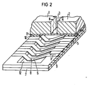
- 2 shows an exemplary embodiment of a writing head for an ink writing device with a plurality of outlet openings, in which the droplet generation takes place according to these features.
- 2 is built up in layers. It has a nozzle plate 7 with the outlet openings or nozzle openings 8.
- the nozzle plate 7 also forms one (lower) wall of an ink chamber 12, the other (upper) wall of which is formed by a sealing plate 11.
- Spacer elements 9 and 10 are arranged between the nozzle plate 7 and the sealing plate 11 over the entire length of the write head. These form the side walls of the ink channel 12. At the same time, they serve to accommodate the actual drive elements 5. This can be done, for example, as shown in FIG.
- the lower spacer element 9 has corresponding recesses into which the drive elements designed as a conductor loop 5 are attached and held on both sides of the ink chamber 12.
- the drive elements can also be formed as contact surfaces when creating the spacer element 9.
- the drive elements 5 can be designed, for example, in the form of narrow metallic strips which have arrow-like bends or legs in the area of the ink chamber, which point forward in the example. This part of the drive element 5 then forms the middle part 6 described above. Its arrangement is such that the front end of each middle part 6 is located directly above an outlet opening 8 of the nozzle plate 7.
- the magnet system in the example a permanent magnet, is arranged above the sealing plate 11.
- the magnetic field lines B of the magnetic field are parted and therefore very dense. They penetrate the arrow-like, in the example facing forward middle parts 6 of the drive elements 5 in such a direction that with a current flow I from right to left (arrow direction in Fig. 2) the middle part 6 of the drive elements 5 is deflected or bent downward.
- a small volume of ink is pressed out of the corresponding outlet opening 8 at high speed and leaves the outlet opening in the form of a droplet.
- the movable middle part 6 of the drive element 5 swings back again and secures the suction of writing fluid by a slight overshoot in the other direction.
- the arrangement is constructed in layers. Since the arrangement is not limited to a specific number of nozzles, and since the magnet system extends over all drive elements 5, 6, that is to say is assigned to all drive elements together, and the entire arrangement consists of a few parts which can be produced and assembled without any significant effort a write head constructed in this way has the dimensions of an entire print line. This advantageously enables use in a line-by-line writing device in which the characters of an entire line of lines are formed line by line by individual dots. The write speeds that can be achieved are significantly higher than those of conventional ink mosaic printers.
- the nozzle plate 7, the spacer elements 9 and 10 and the sealing plate 11 can consist, for example, of so-called plenary layers. 'What can be done in the context of Er is located, the drive elements 5 are formed as plenary layers.
- any characters can be grid-shaped on the Ink carriers of ink droplets sprayed onto them can be built up and displayed.
- the arrangement of the magnet system is not limited to the examples given in FIGS. 1 and 2.
- An example of this is shown in Fig. 3.
- the magnetic field lines are apex and intersect the legs of the drive elements 5 running in the ink chamber 12, i.e. these are in a range of a high magnetic field line density.
- the magnet system can also be constructed from more than two magnetic bodies.
- An exemplary embodiment of this is shown in FIG. 4.
- two magnetic bodies 1 and 2 extend over the sealing plate 11, while a further magnetic body 16 is arranged opposite the nozzle plate 7.
- the magnetic bodies 1, 2 and 16 are arranged such that their poles of the same name, in the example the north poles N, point towards one another.
- a preferably slot-shaped opening 16 is provided in each case for inserting or executing the recording medium 15 into or out of the write head.
Applications Claiming Priority (2)
| Application Number | Priority Date | Filing Date | Title |
|---|---|---|---|
| DE3333939 | 1983-09-20 | ||
| DE3333939 | 1983-09-20 |
Publications (1)
| Publication Number | Publication Date |
|---|---|
| EP0135197A1 true EP0135197A1 (fr) | 1985-03-27 |
Family
ID=6209577
Family Applications (1)
| Application Number | Title | Priority Date | Filing Date |
|---|---|---|---|
| EP84111071A Withdrawn EP0135197A1 (fr) | 1983-09-20 | 1984-09-17 | Système de génération de gouttelettes pour dispositifs d'écriture à encre |
Country Status (3)
| Country | Link |
|---|---|
| US (1) | US4544933A (fr) |
| EP (1) | EP0135197A1 (fr) |
| JP (1) | JPS6090772A (fr) |
Cited By (3)
| Publication number | Priority date | Publication date | Assignee | Title |
|---|---|---|---|---|
| DE3529021A1 (de) * | 1985-08-13 | 1987-02-19 | Siemens Ag | Verfahren zur herstellung von einseitig frei beweglichen metallstrukturen, insbesondere von metallischen antriebselementen fuer einen tintendruckkopf |
| DE3709455A1 (de) * | 1987-03-23 | 1988-10-06 | Siemens Ag | Anordnung fuer einen elektrodynamisch betriebenen tintenschreibkopf |
| DE3732044C1 (en) * | 1987-09-23 | 1989-02-09 | Siemens Ag | Electrophotographic printer |
Families Citing this family (31)
| Publication number | Priority date | Publication date | Assignee | Title |
|---|---|---|---|---|
| DE3333980A1 (de) * | 1983-09-20 | 1985-04-04 | Siemens AG, 1000 Berlin und 8000 München | Anordnung zur reduzierung der nebensprecheinfluesse in tintenschreibeinrichtungen |
| DE3445720A1 (de) * | 1984-12-14 | 1986-06-19 | Siemens AG, 1000 Berlin und 8000 München | Anordnung zum ausstoss von einzeltroepfchen aus austrittsoeffnungen eines tintenschreibkopfes |
| US6629646B1 (en) * | 1991-04-24 | 2003-10-07 | Aerogen, Inc. | Droplet ejector with oscillating tapered aperture |
| US5938117A (en) | 1991-04-24 | 1999-08-17 | Aerogen, Inc. | Methods and apparatus for dispensing liquids as an atomized spray |
| WO1993001404A1 (fr) * | 1991-07-08 | 1993-01-21 | Yehuda Ivri | Ejecteur de liquide a ultrasons |
| US5450115A (en) * | 1994-10-31 | 1995-09-12 | Xerox Corporation | Apparatus for ionographic printing with a focused ion stream |
| US6085740A (en) | 1996-02-21 | 2000-07-11 | Aerogen, Inc. | Liquid dispensing apparatus and methods |
| US6205999B1 (en) | 1995-04-05 | 2001-03-27 | Aerogen, Inc. | Methods and apparatus for storing chemical compounds in a portable inhaler |
| US5758637A (en) | 1995-08-31 | 1998-06-02 | Aerogen, Inc. | Liquid dispensing apparatus and methods |
| US6014970A (en) * | 1998-06-11 | 2000-01-18 | Aerogen, Inc. | Methods and apparatus for storing chemical compounds in a portable inhaler |
| US6782886B2 (en) | 1995-04-05 | 2004-08-31 | Aerogen, Inc. | Metering pumps for an aerosolizer |
| KR100209515B1 (ko) * | 1997-02-05 | 1999-07-15 | 윤종용 | 자성잉크를 이용한 잉크젯 프린터의 분사 장치 및 방법 |
| US6235177B1 (en) | 1999-09-09 | 2001-05-22 | Aerogen, Inc. | Method for the construction of an aperture plate for dispensing liquid droplets |
| US8336545B2 (en) | 2000-05-05 | 2012-12-25 | Novartis Pharma Ag | Methods and systems for operating an aerosol generator |
| US7971588B2 (en) | 2000-05-05 | 2011-07-05 | Novartis Ag | Methods and systems for operating an aerosol generator |
| US6948491B2 (en) | 2001-03-20 | 2005-09-27 | Aerogen, Inc. | Convertible fluid feed system with comformable reservoir and methods |
| US7100600B2 (en) | 2001-03-20 | 2006-09-05 | Aerogen, Inc. | Fluid filled ampoules and methods for their use in aerosolizers |
| US6543443B1 (en) | 2000-07-12 | 2003-04-08 | Aerogen, Inc. | Methods and devices for nebulizing fluids |
| US6546927B2 (en) | 2001-03-13 | 2003-04-15 | Aerogen, Inc. | Methods and apparatus for controlling piezoelectric vibration |
| US6550472B2 (en) | 2001-03-16 | 2003-04-22 | Aerogen, Inc. | Devices and methods for nebulizing fluids using flow directors |
| US6732944B2 (en) | 2001-05-02 | 2004-05-11 | Aerogen, Inc. | Base isolated nebulizing device and methods |
| US6554201B2 (en) | 2001-05-02 | 2003-04-29 | Aerogen, Inc. | Insert molded aerosol generator and methods |
| US7677467B2 (en) | 2002-01-07 | 2010-03-16 | Novartis Pharma Ag | Methods and devices for aerosolizing medicament |
| CA2472644C (fr) | 2002-01-07 | 2013-11-05 | Aerogen, Inc. | Dispositifs et procedes pour la nebulisation de fluides d'inhalation |
| ES2603067T3 (es) | 2002-01-15 | 2017-02-23 | Novartis Ag | Métodos y sistemas para hacer funcionar un generador de aerosol |
| EP1509259B1 (fr) | 2002-05-20 | 2016-04-20 | Novartis AG | Appareil de realisation d'aerosol pour traitement medical et procedes correspondants |
| US8616195B2 (en) | 2003-07-18 | 2013-12-31 | Novartis Ag | Nebuliser for the production of aerosolized medication |
| US7946291B2 (en) | 2004-04-20 | 2011-05-24 | Novartis Ag | Ventilation systems and methods employing aerosol generators |
| JP5064383B2 (ja) | 2005-05-25 | 2012-10-31 | エアロジェン,インコーポレイテッド | 振動システムと方法 |
| US8021014B2 (en) * | 2006-01-10 | 2011-09-20 | Valinge Innovation Ab | Floor light |
| US7997709B2 (en) * | 2006-06-20 | 2011-08-16 | Eastman Kodak Company | Drop on demand print head with fluid stagnation point at nozzle opening |
Citations (3)
| Publication number | Priority date | Publication date | Assignee | Title |
|---|---|---|---|---|
| FR2230879A1 (fr) * | 1973-05-21 | 1974-12-20 | Rca Corp | |
| DE2905063A1 (de) * | 1979-02-10 | 1980-08-14 | Olympia Werke Ag | Anordnung zur vermeidung des ansaugens von luft durch die duesen eines spritzsystems |
| US4336544A (en) * | 1980-08-18 | 1982-06-22 | Hewlett-Packard Company | Method and apparatus for drop-on-demand ink jet printing |
Family Cites Families (3)
| Publication number | Priority date | Publication date | Assignee | Title |
|---|---|---|---|---|
| US3946398A (en) * | 1970-06-29 | 1976-03-23 | Silonics, Inc. | Method and apparatus for recording with writing fluids and drop projection means therefor |
| DE2527647C3 (de) * | 1975-06-20 | 1981-06-25 | Siemens AG, 1000 Berlin und 8000 München | Mit Flüssigkeitströpfchen arbeitendes Schreibgerät |
| US4158847A (en) * | 1975-09-09 | 1979-06-19 | Siemens Aktiengesellschaft | Piezoelectric operated printer head for ink-operated mosaic printer units |
-
1984
- 1984-08-31 US US06/646,146 patent/US4544933A/en not_active Expired - Fee Related
- 1984-09-17 EP EP84111071A patent/EP0135197A1/fr not_active Withdrawn
- 1984-09-19 JP JP59194954A patent/JPS6090772A/ja active Pending
Patent Citations (3)
| Publication number | Priority date | Publication date | Assignee | Title |
|---|---|---|---|---|
| FR2230879A1 (fr) * | 1973-05-21 | 1974-12-20 | Rca Corp | |
| DE2905063A1 (de) * | 1979-02-10 | 1980-08-14 | Olympia Werke Ag | Anordnung zur vermeidung des ansaugens von luft durch die duesen eines spritzsystems |
| US4336544A (en) * | 1980-08-18 | 1982-06-22 | Hewlett-Packard Company | Method and apparatus for drop-on-demand ink jet printing |
Non-Patent Citations (3)
| Title |
|---|
| IBM TECHNICAL DISCLOSURE BULLETIN, Band 16, Nr. 2, Juli 1973, Seiten 467-468, Armonk, New York, US; F. HOCHBERG u.a.: "Multinozzle line printer using electromagnetic valving" * |
| IBM TECHNICAL DISCLOSURE BULLETIN, Band 16, Nr. 6, November 1973, Seite 1834, Armonk, New York, US; A.H. BATTISON u.a.: "Moving coil ink jet print head" * |
| IBM TECHNICAL DISCLOSURE BULLETIN, Band 18, Nr. 7, Dezember 1975, Seiten 2195-2196, Armonk, New York, US; E. LENNEMANN u.a.: "Mercury controlled ink jet" * |
Cited By (3)
| Publication number | Priority date | Publication date | Assignee | Title |
|---|---|---|---|---|
| DE3529021A1 (de) * | 1985-08-13 | 1987-02-19 | Siemens Ag | Verfahren zur herstellung von einseitig frei beweglichen metallstrukturen, insbesondere von metallischen antriebselementen fuer einen tintendruckkopf |
| DE3709455A1 (de) * | 1987-03-23 | 1988-10-06 | Siemens Ag | Anordnung fuer einen elektrodynamisch betriebenen tintenschreibkopf |
| DE3732044C1 (en) * | 1987-09-23 | 1989-02-09 | Siemens Ag | Electrophotographic printer |
Also Published As
| Publication number | Publication date |
|---|---|
| US4544933A (en) | 1985-10-01 |
| JPS6090772A (ja) | 1985-05-21 |
Similar Documents
| Publication | Publication Date | Title |
|---|---|---|
| EP0135197A1 (fr) | Système de génération de gouttelettes pour dispositifs d'écriture à encre | |
| DE2944005C2 (fr) | ||
| DE2945658C2 (fr) | ||
| EP0128456B1 (fr) | Tête d'écriture à commande piézo-électrique | |
| DE2543451C2 (de) | Piezoelektrisch betriebener Schreibkopf für Tintenmosaikschreibeinrichtungen | |
| DE3012720C2 (fr) | ||
| DE3202937C2 (de) | Tintenstrahlaufzeichnungskopf | |
| DE60111817T2 (de) | Tintenstrahlgerät mit verstärkter tropfenumlenkung durch asymmetrische beheizung | |
| DE3245283A1 (de) | Anordnung zum ausstoss von fluessigkeitstroepfchen | |
| DE3248087A1 (de) | Fluessigkeitsstrahlkopf | |
| EP0121894B1 (fr) | Tête d'écriture commandée par piézo-électricité pour dispositifs d'écriture à mosaique d'encre | |
| DE3445720A1 (de) | Anordnung zum ausstoss von einzeltroepfchen aus austrittsoeffnungen eines tintenschreibkopfes | |
| DE2344453A1 (de) | Tintenstrahlmatrixdrucker | |
| EP0150348B1 (fr) | Tête d'impression à jet d'encre | |
| DE3804456C2 (fr) | ||
| DE3246839A1 (de) | Schreibkopf fuer einen impulsstrahl-tintenstrahlschreiber | |
| DE2812372A1 (de) | Tintenstrahldruckkopf | |
| DE2808275C2 (de) | Tintenstrahldruckkopf | |
| DE3500985A1 (de) | Anordnung zur erzeugung von einzeltroepfchen in tintenschreibeinrichtungen | |
| DE2703320A1 (de) | Troepfchenstrahlen-aufzeichnungsvorrichtung | |
| DE2554457A1 (de) | Tintenstrahl-drucker | |
| DE3018334C2 (fr) | ||
| EP0030382A1 (fr) | Tête d'écriture pour dispositif d'écriture à mosaique d'encre | |
| EP0034777A1 (fr) | Installation d'écriture à l'encre | |
| EP0040784A2 (fr) | Agencement pour une tête d'impression dans un dispositif à écrire à jets d'encre en forme de matrice de points |
Legal Events
| Date | Code | Title | Description |
|---|---|---|---|
| PUAI | Public reference made under article 153(3) epc to a published international application that has entered the european phase |
Free format text: ORIGINAL CODE: 0009012 |
|
| AK | Designated contracting states |
Designated state(s): CH DE FR GB IT LI NL SE |
|
| 17P | Request for examination filed |
Effective date: 19850129 |
|
| STAA | Information on the status of an ep patent application or granted ep patent |
Free format text: STATUS: THE APPLICATION HAS BEEN WITHDRAWN |
|
| 18W | Application withdrawn |
Withdrawal date: 19860402 |
|
| RIN1 | Information on inventor provided before grant (corrected) |
Inventor name: HEINZL, JOACHIM, PROF. DR.-ING. |